Indu-Sol PROFInet-INspektor User manual
Diagnostic and service tools for PROFINET
Your partner and specialist for field bus systems, Industrial Ethernet and PROFINET
PROFInet-INspektor®
MANUAL
Indu-Sol GmbH • Blumenstrasse 3 • D - 04626 Schmoelln • Germany
Telephone: +49 34491 5818-0 • Fax: +49 34491 5818-99 • E-Mail: info@indu-sol.com • www.indu-sol.com


List of revisions
Date Revision Change(s)
08/06./2011
0 First version
25/10/2011 1 Revised version
05.02.2012 2 Revised version
04.04.2012 3 Revised version
27.08.2012 4 Revised version
© Copyright 2011 Indu-Sol GmbH
We reserve the right to make changes without prior announcement. Our
products are subject to constant improvement. We also reserve the right to
change the scope of supply as regards form, configuration and equipment.
No claims can be derived from the data, figures and descriptions of this
documentation. Any reproduction, processing and translation of this
document or any extract thereof are subject to written approval by Indu-Sol
GmbH. All rights pursuant to the copyright law shall be expressly reserved
to Indu-Sol GmbH.
Attention!
This device may only be started and operated by qualified personnel.
Qualified personnel within the meaning of the safety information
contained in this manual are persons who are authorized to start, ground
and mark devices, systems and circuits in accordance with the safety
standards. .

Table of contents
1 General 6
1.1
Scope of supply 6
1.2
Safety information 6
1.3
Purpose of use 6
2 Installation 7
2.1
Connecting the voltage supply 7
2.2
Connecting to PROFINET 7
3 Electrical connections 8
3.1
Voltage supply 9
3.2
Web interface 9
3.3
COM 10
3.4
Mirror Port 12
3.5
NETWORK IN 12
3.6
NETWORK OUT 12
3.7
RESET button 12
3.8
LED functions 13
3.8.1
PWR 13
3.8.2
LAN 13
3.8.3
RUN 13
3.8.4
ERROR 13
3.8.5
ALARM 13
4 Web interface 14
4.1
Display of web interface 14
4.2
Parameters of web interface 15

4.2.1
External diagnosis 15
4.2.2
Internal diagnosis 15
4.2.3
Utilization 15
4.2.4
Data throughput 15
4.2.5
Refresh rates – telegram jitter 16
4.2.6
Connection attempts 16
4.2.7
Error telegrams 16
4.2.8
Package types 16
4.3
The network statistics 17
4.4
Buttons and possible settings 17
4.4.1
Buttons on start page 18
4.4.2
Threshold values and alarms 19
4.4.3
Last cycle 19
4.4.4
Designation of subscribers 19
4.4.5
System settings 20
5 Technical data 21
6 CE Declaration of Conformity 22
7 Notes 24

General
sh. 6 of 26
1 General
Read the entire content of this document carefully before you install
and start up this device.
1.1 Scope of supply
The following components: are included in the delivery:
•PROFInet-INspektor
®
- PIT hardware
•24V voltage supply connector
•Software CD
•Installation manual
Check for completeness prior to start-up.
1.2 Safety information
Never open the housing of the PROFInet-INspektor
®
.
If the device is assumed to be defective, send it back to the supplier.
Warranty will expire immediately if the housing is opened.
1.3 Purpose of use
The PROFInet-INspektor
®
is designed to permanently monitor the
PROFINET in automation systems.
Never use the device in explosion-hazardous areas.

Installation
sh. 7 of 26
2 Installation
The PROFInet-INspektor
®
is snapped horizontally onto a TS35 DIN
mounting rail in the switchgear cabinet.
The PROFInet-INspektor
®
is cooled conventionally by heat exchange
with the ambient air.
When installing the device make sure that the venting slots of the
device are not obstructed by other components. An all round
distance of 30 mm to other devices should be ensured.
2.1
Connecting the voltage supply
Provide the PROFInet-INspektor
®
with the necessary voltage of 24
V DC, Observe the polarity. The PE terminal can be used as
protective earth.
2.2
Connecting to PROFINET
Now, that the voltage supply has been connected you have to
connect the PROFInet-INspektor
®
with the PROFINET. To this end
connect the outgoing line of the controller with the "Network IN"
interface and route the "Network OUT“ interface to the other field
devices..
If the device is connected via an ETMA (TAP) , keep in mind that the
incoming line needs to be a crossover cable because otherwise the
internal pair allocation of the interfaces will be incorrect and the
analysis cannot be started.
The PROFINET-INspektor
®
starts automatically analysing the
PROFINET data traffic.
Device names will only be recognized in the run-up phase of the
PROFINET, however.

Electrical connections
sh. 8 of 26
3 Electrical connections
Fig. 1 is a schematic representation of the PROFInet-INspektor
®
Fig. 1: Front view of the PROFInet-INspektor
®

Electrical connections
sh. 9 of 26
3.1 Voltage supply
The PROFInet-INspektor
®
is supplied with 24V DC. The required
terminal strip is included in the scope of supply. The voltage supply
connection is shown in Fig. 1 as "DC 24V".
The L+ terminal is supplied with +24V and the M terminal with 0 V.
It is also necessary to provide a PE connection. Where a strong
electromagnetic radiation is present in the environment of the
PROFInet-INspektor
®
the earthing screw under the web interface
port should be additionally connected.
The voltage supply cables should have a minimum cross section of
0.75mm² and max.1.5mm².
The PROFInet-INspektor
®
has an internal overvoltage protection.
The latter triggers at voltages above 30 V and can be replaced by
Indu-Sol GmbH only.
IMPORTANT:
Under normal operating conditions the PROFInet INspektor
®
has a
power consumption of 500mA. In the starting phase, however, 3 A
will be needed for a short period of time. Please keep that in mind
when you choose the power pack.
3.2 Web interface
The web interface is the connection for data evaluation. It is a
10Base-T/100Base-TX RJ45 interface.

Electrical connections
sh. 10 of 26
3.3 COM
The serial COM-interface is not sourced on the PROFInet-
INspektor
®
.

Electrical connections
sh. 11 of 26
Signal inputs and outputs
The six-pole input and output interface is assigned as follows:
OUT
IN
Input 1: Reset PROFInet-INspektor
®
- PIT
Input 2: Alarm acknowledgement (Reset the switch contact including
clearing of alarm list)
Input 3: Alarm acknowledgement (Reset the switch contact
with no clearing of alarm list)
Output:
- floating relay contact
- max. 24V DC +20%
- max. 1 A
- Polarity is not an issue
3 inputs:
- max. 24V DC ±20%
- inactive < 3V
- active > 10V
- maximum power 0.15mA
- electrically isolated
GND:
- frame potential of inputs
1
2
3
GND
OUT
OUT

Electrical connections
sh. 12 of 26
3.4 Mirror Port
The mirror port has a 1000Base-TX RJ45 interface. All telegrams of
the PROFINET can be recorded at this port by an Ethernet telegram
analyzer. .
IMPORTANT:
THE PC USED FOR DATA RECORDING MUST HAVE
1000BASE-TX RJ 45 INTERFACE (GIGABIT).
3.5 NETWORK IN
The NETWORK IN port renders the connection between the control
system and the PROFInet-INspektor
®
. To this end it is necessary to
connect the control system directly with the INspektor
®
via a RJ45
PROFINET cable.
3.6 NETWORK OUT
The NETWORK OUT port connects the PROFInet-INspektor
®
with
the entire system network.
IMPORTANT:
The "NETWORK IN"AND "NETWORK OUT"PORTS ARE FIRMLY
CONNECTED WITH EACH OTHER. IT MEANS THAT THE
PROFINET NETWORK KEEPS RUNNING EVEN IF THE POWER
FAILS OR THE PROFINET INSPEKTOR IS DEFECTIVE.
3.7 RESET button
A RESET button is provided on the rear side of device. This button
can be used to reset all settings to the initial status. For this purpose
press the button for at least 10 seconds.
IMPORTANT:
‘ANY RESETTING OF THE DEVICE ALSO RESETS THE
LICENCE. DO NOT FORGET TO SAVE IT BEFOREHAND.

Web interface
sh. 13 of 26
3.8 LED functions
3.8.1 PWR
The POWER LED indicates the status of the voltage supply.
A green light means that 24 V are available.
If it fails to light up, it is an indication of absent power supply or an
internal defect and that the overvoltage protection has triggered
respectively. Whatever the cause, it will be necessary to return the
device for repair.
3.8.2 LAN
The LAN LED lights up as soon as the web interface is connected
with an active Ethernet subscriber.
3.8.3 RUN
The RUN LED lights up green as soon as the device is fully
operational.
3.8.4 ERROR
The ERR LED lights up red when an internal device defect occurs.
3.8.5 ALARM
The ALARM LED lights up red in case of an alarm. The light is
green as long as there is no alarm.

Web interface
sh. 14 of 26
4 Web interface
4.1 Display of web interface
To access the web interface and the recorded data of the PROFInet-
INspektor
®
, open the web interface using the internet browser and the IP
address of the device (Default: 192.168.212.212).
Fig. 1: Web interface
It is now possible to view and check the most important parameters of the
PROFINET system to be analyzed.
Said parameters are given in the central table of the website.
Shown are all PROFINET devices involved in the PROFINET traffic. The
default display gives the MAC address and the name of the device (if a
PROFINET restart has been made). In the ”Events” dropdown menu the
parameters given in the table can be allocated to the individual subscribers.

Web interface
sh. 15 of 26
The table columns show the timing of the events. The ”Last minute” column
shows the current condition of the PROFINET network. The ”Last cycle”
column shows the most recent cycle set (1- 120 hours). The ”History”
column gives all data from the beginning of the analysis and after Delete
data/List respectively.
4.2 Parameters of web interface
4.2.1 External diagnosis
If an PROFINET I/O device detects a problem that occurs
externally at the device (no load voltage, actor-sensor short circuit
etc.), this device keeps on communicating but sends an alarm to
the controller to report this condition
4.2.2 Internal diagnosis
An internal diagnosis of a field device will be communicated if the
device has an internal fault, the configuration is no longer in
conformity or the device suffers serious defects. In most cases it
results in a restart of the device.
4.2.3 Utilization
The utilization describes the use of the bandwidth which is 100
Mbit/ for PROFINET. In other words: 20 Mbit/s are transmitted at a
utilization rate of 20%. Indu-Sol’s experience has shown that the
utilization rates should not be greater than 20%. For the
acceptance of a system the network quality in terms of with
"utilization"must be verified through a permanent recording of the
telegrams.
4.2.4 Data throughput
The term "data throughput"in the PROFINET means an amount of
data per unit of time that can be processed by the relevant control
system (related to the process image). As a standard value 4,500
Byte/ms should not be exceeded for this purpose. The value
obtained should be documented as reference value.

Web interface
sh. 16 of 26
4.2.5 Refresh rates – telegram jitter
The refresh rate is a firmly set value (for every device) in the control
system (e.g.1ms) that determines the refresh interval of data
between the control system and the IO device. Essential for the
actual refresh rate is the line depth, i.e. the installed network
structure and the number of device transitions. The rising number
of device transitions causes a variance in the running time of the
telegrams that is called ‚jitter‘. The measurement of the refresh
rate is to verify that the telegram jitter up and down does not
exceed half a refresh rate.
4.2.6 Connection attempts
The Connection Attempts parameter shows how often a device
attempted in vain to contact the controller after a failure.
4.2.7 Error telegrams
It gives the number of error telegrams arriving at the PROFInet-
INspektor
®
(checksum error and package fragments)
4.2.8 Package types
Different
packages are counted to get a full view of all
communication in the network. It may also be evaluated in a
graphical manner by using the network statistics item.

Web interface
sh. 17 of 26
4.3 The network statistics
The Network Statistics item is designed to count again the different
package types and display them graphically. The ratio of PROFINET
data to other data should not be less than 100:1.
Fig. 2: Network statistics
4.4 Buttons and possible settings
Buttons and Extended Settings are available to reset data or make
extended settings,
Web interface
sh. 18 of 26
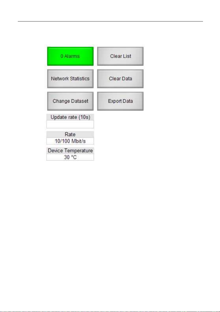
4.4.1 Buttons on start page
Fig. 3: Buttons of start page
Alarms -> Shows alarm list
Network statistics -> Shows network overview
Change data record -> Changes the current data record (4 data
records in ring buffer)
Clear list -> Entries in table are set to 0, devices and their names
are maintained, however.
Clear data -> Entries in table are reset including all devices and
names.
Export data -> Listing of recorded data
Web interface
sh. 19 of 26
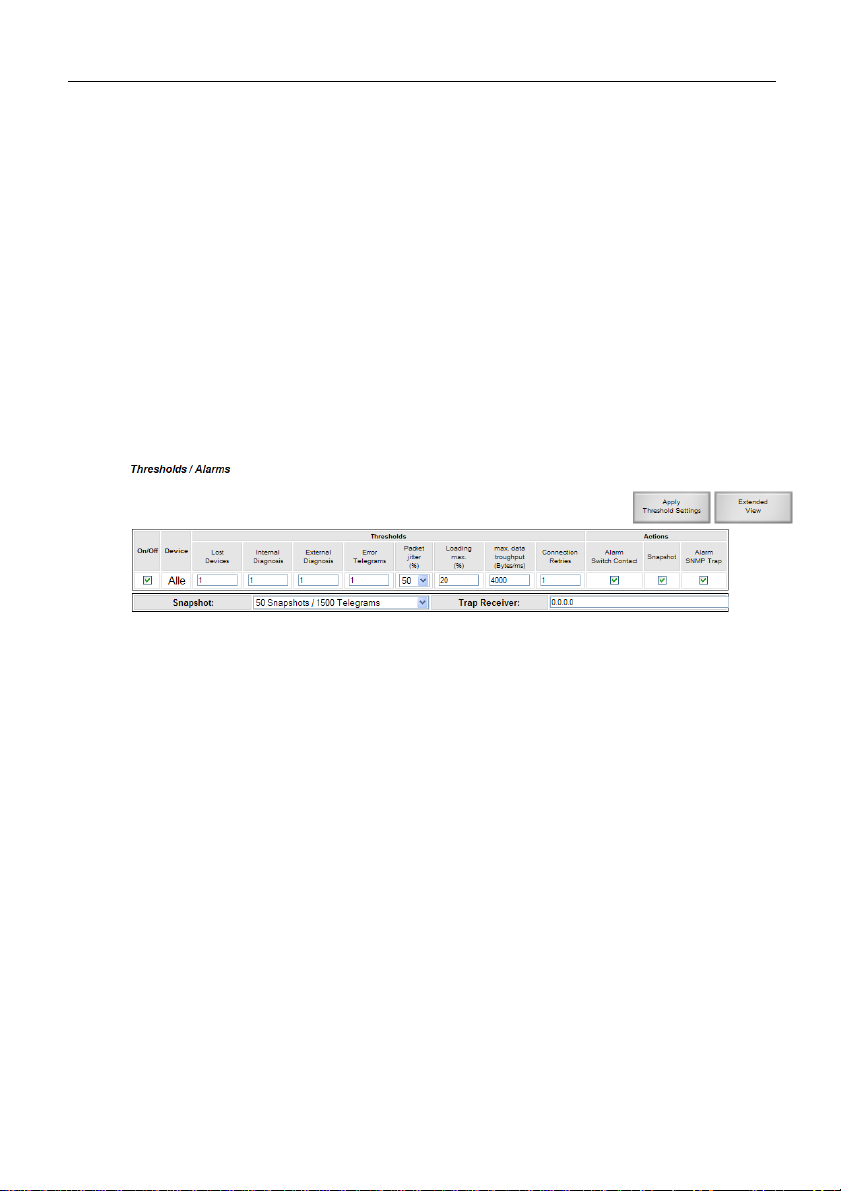
4.4.2 Threshold values and alarms
What is an alarm?
An alarm is triggered as soon as a preset or default threshold value
is exceeded. This event results in a graphic display on the website
and the device, the sending of an Ethernet trap and the switching
of the floating contact.
In the list of threshold values and alarms the threshold values and
the associated triggering of alarms can be set for all subscribers
together or each individual subscriber.
Fig. 4: Threshold values and alarms
4.4.3 Last cycle
The Last Cycle only refers to the set period of analysis but not to
the ”bus cycle”
The time span of the last cycle can be set from one hour to
maximum 120 hours.
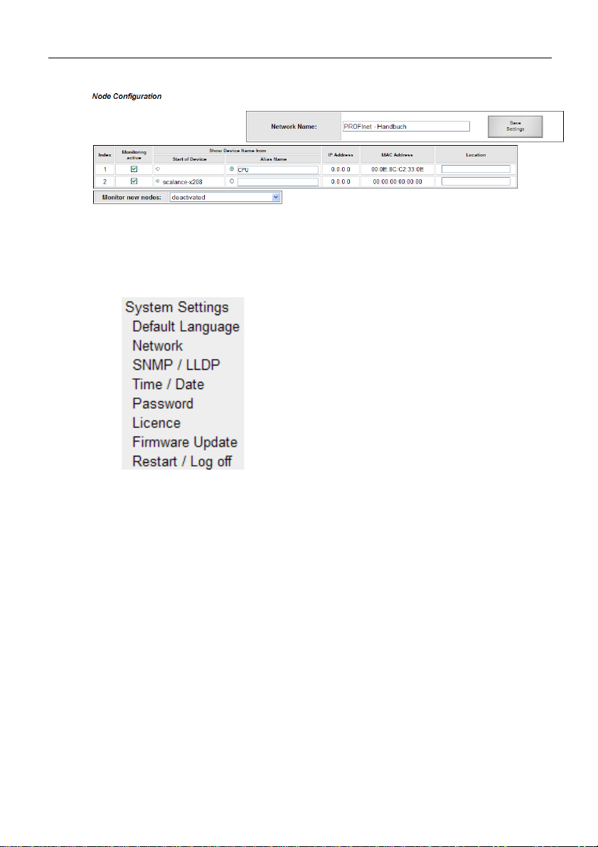
4.4.4 Designation of subscribers
At the run-up of a PROFINET network the subscriber names of all
devices are displayed. If these names are not informative, a restart
is impossible or an alias name is to be displayed, it can be done
now. Controller names are not recognized during the run-up and
must therefore get an alias name.
Web interface
sh. 20 of 26
Fig. 5: Designation of subscribers
4.4.5 System settings
Under System Settings all settings of the device can be adjusted.
Fig. 6: System settings
Default language -> to define the language of the website when
selected.
Network -> to set the network parameters
SNMP/LLDP -> to set the SNMP name and parameters
Time/Date -> to set date and time
Password -> to set the password for all users incl. setting of
password prompt.
License -> view of license and possible upgrade by input of a
license code
Firmware update -> to load new firmware
Restart/Logout: to logout active user or device restart.
Table of contents
Other Indu-Sol Diagnostic Equipment manuals


