Industrial Dynamics Filtec FT-50 Assembly instructions

Ultraviolet Label Detector
Installation and Setup Guide for
Models FT-50 and FT-70
2326-1292

Ultraviolet Label Detector
Installation and Setup Guide for Models FT-50 and FT-70
Document 2326-1292

Industrial Dynamics Company, Ltd.
Document 2326-1292 Copyright. All rights reserved.
No part of this publication may be reproduced or used in any form or by any means (graphic,
electronic, or mechanical including photocopying, recording, taping, or information storage
and retrieval system) without written permission of Industrial Dynamics Company, Ltd.
Filtecand Industrial Dynamicsare registered trademarks of Industrial Dynamics Company,
Ltd. All other trademarks are the property of their respective owners.
Contact Information
Corporate Headquarters: 3100 Fujita Street,
Torrance, California
90505-4007
U.S.A.
Telephone:(310) 325-5633
FAX: (310) 530-1000
Internet: www.filtec.com
Mailing Address: P.O. Box 2945,
Torrance, California
90509-2945
U.S.A.
Shipping Address: 3100 Fujita Street,
Torrance, California
90505-4007
U.S.A.
Customer Service: (800) 733-5173

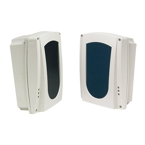
The Ultraviolet Label Detector inspects full
-
wrap body or neck
labels on unoriented containers, or front/back, front or back
labels
on
oriented containers.
The UV
Label
Detector
is
a
photoelectric sensor which is
designed to detect the presence of luminescent/fluorescent
chemicalsand materials, which are invisible except under
ultraviolet light
(see
Figure
1).
When exposed to the ultraviolet
light
from
the scanner, these chemicals
"
fluoresce
"
and emit
visible light, which
is
then
detected
by the sensor. An amplifier
with sensitivitycontrol
is
included in the waterproof self
-
contained unit.
The mounting bracket for the UltravioletLabel Detector allows
sensor positioning as follows:
Horizontal
-
approximately
2.5
inches
Vertical
-
Height
of
vertical tube
Ultraviolet
Label
Detector power
(+20VDC
and ground)
is
suppliedby the Main Terminal Block
TB1
in
the Inspection
Head through the cable connecting the
FT-50
to the Ultraviolet
Label Detector sensor.
The Ultraviolet
Label
Detector requires an optional Encoderbe
installed
in
the system to provideaccurate measure of conveyor
travel. This
will
ensure the sensor
scans
the bottle's inspection
zone during the Look Distance Gate.
Figure
1.
UltravioletSensor
Industrial
Dynamics
Company,
Ltd.
2326-1292
1

FUNCTIONS
The
FT
-
50/70
menu for your systemincludes functions that are
used
to
describe
the label sensors
to
the
FT
-
50/70
software
program, define the inspection parameters and reset the reject
counters. The functions are accessed through the Control Panel.
NOTE:
A
feature of the system allowsselecteddisplayedmessages to
be customized for
a
particular applicationwhen the system is
configured
at
Industrial Dynamics. For example,
‘LABEL
TYPE
-
’
functionsand associated messages
(STATUS,
TOTAL, RESET,
etc.) may be changed to display as MISSING
BODY LBL
STATUS,
TOTAL
MISSING
BODY LBL,
etc. In
addition, when only one downstream station is included in the
system, the messages will substitute
LABEL
in place of
‘STATION
n’.
LABEL
TYPE
A(B,
C
OR
D)
STATUS
Toggles the function
ON
of
OFF
for the inspection type
displayed. The letter designates a specific inspection
type
associated with the sensor. Allows the function
to
be
turned
ON
of
OFF
in both the OPERATE and the CALIBRATE modes.
(Range:
ON
or
OFF,
Default:
OFF)
TRIGGER
TO
STATION
1
(or
2)
The distance, in millimeters, between the centerline
of
the
Inspection Trigger Beam and the centerline
of
the Ultraviolet
sensor.
This
distance is used by the processor to establish the
proper timing for inspection
Look
Distance. The range
(minimumand maximum distance)
is
established by the position
of the Rejector relative to the Inspection Trigger Beam. The
centerline of the detectorcannot be closer than one container
diameter plus
1
mm
to
the Trigger Beam centerline and should
not be closer than
two
container diameters from
the
centerline
of
the
Rejector.
On
a
production line where inspection space
is
limited and the
physicaldimensions of the station permit, the minimum distance
from the Rejector can be calculated by multiplying the
’Maximum
Production Chain Velocity (metersper minute)’
times ’Rejector Reaction Delay Time plus
1
ms’ (in milliseconds)
plus
1/2
the
Look
Distance’ (in millimeters). The system will
2
Industrial
Dynamics Company,
Ltd.
2326-1292

not allowa value to be entered that
will
place the center
of
the
Look
Distance closer that one container diameter plus
1
millimeter. (Default:
150
mm for station
1
and
202
mm for
station
2)
LOOK DlST STATION 1
(or
2)
Adjusts the distance, in millimeters, during which the label
sensor output will be accepted by the processor.
This
gate is
centered on the point established by the TRIGGER TO
'STATION n' function. (Range:
1
to
250
mm,
Default:
12
mm)
ADJUST DlST STATION 1
(or
2)
Adjusts the distanceset in TRIGGER TO 'STATION n' using the
FT
-
50/70
Display as amonitor.This function
is
used in the
calibration mode. Refer to Set
-
up procedures.
TOTAL LABEL TYPEA(B, C
or
D)
Displays the total number of containers that failed inspection of
that type since the last time the counter was reset. (Range:
0
to
99,999,999)
RESET LABEL TYPEA(B, C
or
D)
When selectedand executed by pressing either
UP
or DOWN
arrow key, resets the TOTAL LABEL TYPE A
(B,
C or D)Rejects
Counter.
If
the previous count value
is
to be saved,
it
must be
recorded externally; there
is
no storage for the number in the
Counter once
it
is
reset.
LAST RESETDETECTED
Displays the cause for the last reject.
If
caused
by
a
missing
label, the bottom line of the
Display
will showLABEL TYPE
A
(B,
C,
or
D).
ALARM LABEL TYPEA(B,
C
of
D)
Sets the number of consecutive LABEL
TYPE
A
(B,
C or
D)
rejects
that
will
cause an
alarm
condition. Rejects must be
consecutive. Each good container that passes through the
FT
-
50/70
will
resetthe
Alarm
Counter to zero. (Range:
OFF,
1
to
250,
Default:
OFF)
INSTALLATION REQUIREMENTS AND INSTRUCTIONS
The Ultraviolet
Label
Detector mounted
on
its Mounting Pole
will
generallybe installed
at
the same time as
the
FT
-
50/70
System
it
is
being used
with.
The Detector
and
its Mounting Pole are shipped with minimal
assembly required. The only electrical
wiring
required is
connection to the
FT
-
50/70.
Refer
to
Drawing Number
25058
and
the system Installation Drawing for your system for instructions
installing the Ultraviolet Label Detector.
Industrial
Dynamics
Company,
Ltd.
2326-1292
3

Verify the station
is
configured properly
and
that the sensor is
mounted on its mounting
pole
in
approximately the correct
position per the installation drawing for your system.
Verify the wiring connections
from
the sensor to the Main
Terminal
Block
TB1
in the
FT
-
50/70
Inspection Head. Use thestandard wiring information presented in the
FT
-
50/70
manual
and
Drawing
25058
at
the back
of
this appendix. If the
TB1
pin
connections are not standard, a separate wiring diagram will be
included in the documentation sent with your system.
SETUP, ALIGNMENT AND CALIBRATION PROCEDURES
The procedures in the following paragraphs give step-by-step
instructions for the mechanical alignment and electrical
calibration of the Ultraviolet Label Detector Sensor/Amplifier.
Before setting up the Ultraviolet Label Detector, The
FT
-
50/70
Inspection Head Trigger, Encoderand Rejector must be set up
and calibrated.
In
addition, the bottle guides must be positioned
to deliver the bottles to the center
of
the conveyor.
Place a productionbottle on the conveyor
at
the Sensor
centerline and in the approximate position
of
a bottle delivered
by the bottle positioning guide rail.
Adjust the position
of
the UltravioletLabel Sensor
so
that the
sensor
will
intersect the label at
its
widest point. There are two
adjustment knobs on the Detector; one each for the vertical and
the horizontal. Both
will
need to be adjusted to position the
sensorapproximately
1.6
inches from and perpendicular
to
the
label surfaceat a height that allows the sensor to detect the
largest portion
of
a properly positioned label. The final sensor
height
will
be a function of the label fluorescence and sensor
calibration setting.
Firmly tighten the
locking
knobs on the bracket.
Mechanical Alignment
Calibration
Refer
to
your
FT
-
50/70
manual for power turn
-
on and electrical
startup procedures. After the power
is
on, perform the following
calibration steps.
Remove the washdown coverand set aside.
Beforeattempting to calibrate the sensor, make sure the lens on
the front
of
the sensor
is
clean and unobstructed.
4
Industrial
Dynamics
Company,
Ltd.
2326-1292

Place a production bottle on the conveyor at the station
centerline and
in
the approximate position
of
a bottle delivered
by the bottle positioning guide
rail.
Ensure that the bottle
is
approximately
1.6
inches from the lens
of
the sensor and that
the bottle has the proper label
to
be inspected.
Remove the plug on top
of
the Ultraviolet sensor (see Figure
2).
Using a
small
flat blade screwdriver, ensure that the Output
Current trimmer and the Time Delay trimmer are both fully
counterclockwise.
Turn
the Sensitivity Control
pot
fully
counterclockwiseto the minimum sensitivity and then gradually
clockwiseuntil the red
LED
on the sensor comes
ON.
Turn
the
Sensitivity
pot
1/2
the distancebetween this
point
and the
maximum
of
the
pot.
Replace the plug and the washdowncover. Tighten all nuts
and
bolts. Mark the vertical mounting
pole
for
this bottle type.
This
concludesthe mechanicalalignment and electrical
calibration portion
of
the
setup.
Figure 2.
Sensor
Controls
Industrial
Dynamics
Company,
Ltd.
2326-1292
5

SOFTWARE SETUP
The following proceduresassume the
operator
is
familiar with
the setup proceduresand the operating instructions in the
FT
-
50/70
manual.The Ultraviolet Label Detector functions
will
be
discussed
in
the order they are used which roughly corresponds
to the sequenceof appearance on the display.
All
parametervalues are
to
be
entered
in
the CALIBRATE
mode.
Select
this
mode
by pressing the SYSTEM key
repeatedly
until the top line of the Display showsSYSTEM DISPLAY. Next,
press the
UP/DOWN
arrow keys
until
the bottom line displays
CALIBRATE. The system will remain in the CALIBRATE mode
until set to OPERATE mode by the operator
or
until
30
minutes
passes without a panel entry.
Obtain several properly
filled
and labeled
test
bottles
for
each
type bottle
to
be run on this line.
Use
the
VIEW
TB1
PIN
ASSIGNMENTS
subfunction
for
definition of the following:
Input number assigned to
the
physical sensor
Input
to
station assignment
Input signal polarity
Input pin number on terminal block
TB1
in
the inspection head.
Under CAP Options, perform the setup of the Ultraviolet Label
Detector as described
in
the following paragraphs.
NOTE:
Before setting up the Ultraviolet Label Sensor, the
FT
-
50/70
Inspection System, Encoder and Rejector must be setup,
aligned and calibrated.
There
are
four Label Types (A,
B,
C
and
D),
all
identical,
to
process
the inputs from the sensors. Label Type
A,
B,
etc,
designations
are used
to
differentiate the various label sensing
applications. The Label Types are assigned
to
sensor inputs
at
the factory. The Ultraviolet Label Detector employs
1
input for
single (Front or Back) label applications,and
2
inputs
for
dual
(Front and Back) label applications.
Press the CAP Optionskey (button number
2)
repeatedly until
the top line of the Display showsLABEL TYPE A STATUS (this
assumes Type A has not been assigned
to
another label sensor)
or the
text
assigned
to
your application;
LE.
MISSING
FRONT
or BACK LABEL.
Press
the
UP/DOWN
arrow keys until
the
bottom
line
shows
ON. This activates this label
type.
6
Industrial Dynamics
Company,
Ltd.
2326-1292

Perform the next step only
if
the
Ultraviolet Label Detector
is
the first label sensor
to
be setup.
Set DistanceFrom Triggerto Detector Centerline
Accurately measure the distance from the centerline of the
Inspection Trigger Beam
to
the centerline
of
the Ultraviolet
Detector. Press the CAP Optionskey until the
Display
shows
TRIGGER
TO STATION
1,
or the Text assigned to the sensor.
Use
the UP/DOWN arrow keys
to
set
the bottom line
of
the
Display
to
the measured value
in
millimeters (multiply by
25.4).
Look
Distance Gate
Accurately
measure
the width
of
the label
to
be inspected
at
the
centerline
of
the sensor lens. Convert this value to millimeters
and subtract
15
mm (this is the beam width
of
the Ultraviolet
sensor). Press the CAP Options key until the Display shows
LOOK
DIST 'STATION n
or
the Text assigned
to
the sensor.
Use
the UP/DOWN arrow keys to set the bottom line
of
the
display to the value obtained above.
CAUTION:
If other sensors are located
on
the
same
centerline of this
Ultraviolet sensorand they were setup fist, perform the
calibration steps
that
follow but
do
not
adjust
the distance
using the
UP/DOWN
arrow
keys.
Instead, move the sensor
physically
to
center its beam
on
the same centerline.
Adjust
Distance From Triggerto Sensor
The next step
is
to
adjust the distance from the Inspection
Trigger Beam
to
the centerline
of
the Ultraviolet Label Detector
using the
system
software. The Adjust Label Distancefunction
allows the fine tuning
of
the 'Station n
distance
to
eliminate
any
minute errors
that
may be
in
the
system.
ADJUST DISTANCE PROCEDURE
Press the CAP Options key until the
top
line of the Display
showsADJUST DIST 'STATION n
or
the Text assigned to
the
sensor. The bottom line will show
EXECUTE.
Press
either the
UP
or
DOWN arrow key. The information messages and
a
prompt message
are
then displayed:
Industrial
Dynamics
Company,
Ltd.
2326-1292
7
CAUTION:

The first
two
messages are displayed for approximately four
secondseach. The last message will wait for the sensor number
to be entered. Press the number key corresponding
to
the sensor
to be used for centering the gate.
NOTE:
If only one sensoris assigned
to
the
station,
the
prompt
message
will
not
appear
on the
display
The top line of the Display
will
now show
CENTER
GATE
(?=EXIT)and the bottom line
will
flash
READY.
Pass
a properly
filledand labeled test bottle through the Inspection Head and
the bottom line
will
show the Look Distance Gate centering
results on the container. The center of the Look Distance Gate
is
shown on the second line by a
"1"
(sensornumber used for
centering) and the center of the container by a
"
The
"
I"
will
always be centered on the display and the position of the Look
Distance Gate
"
1
"
will
move around.
If
the
time
for the Look
Distance Gate
is
correct,
it
will
be centered on the center of the
bottleand an
*
will be seen in the center of the display (see
examples).This
is
the optimum position
for
the Look Distance
Gate. The position of the
"
1
"
will jump around on the display
due to the differenceof containerdiameter and the variations
caused by a container not being delivered exactly
in
the same
position each time.
If
the distanceat the start
of
the calibration
is
too
far
off, an arrow at the end of the
display
will
show the
limit
(one container diameter on each side
of
the
"
I
"
)
was
exceeded indicating the conveyor is running
too
slow or the
Encoder functions are not set properly.
The operatorwill have to
look
at the results of
5
to
10
containers
beforethey get a good picture of what
is
going on
in
the system.
If the
"
1
"
is located
to
the right of the
"
I
"
,
the distance from the
Inspect Trigger Beam Centerline
to
the centerline of the
Downstream Station (sensor)is
too
long and must be reduced
by using the
DOWN
arrow
on
the panel
until
the
"
1
"
position is
proper. If the
"
1
"
is located to the left
of
the
"
I
"
,
the distance
is
too short and the
UP
arrow on the display must be
used.
When the distance value is incrementedor decremented using
the
UP/DOWN
arrow keys, the bottom lineof the display will
change
to
showSTATION n DIST
=
nnn
MM
where
nnn
is
the
current incremented/decremented value.
Exampledisplays:
8
Industrial
Dynamics
Company,
Ltd.
2326-1292

NOTE:
Due
to
the variation in bottle diameters and delivery
positions, the system will not remain in calibration for every
containerpassing through the Inspection Head. The object is
to
getthe display
to
show
*
as
often
as
possible.
To exit this function, press the DIAGNOSTICS key
(?)
and the
Display will show:
Press the CAP Options key until TRIGGER TO STATION n
is
displayed.
Record
the distance shown on the second line.
Repeat the Adjust Distance calibration
steps
for any other
sensors
on this station. When complete, record the distance
displayed under the TRIGGER TO STATION n function. Try to
adjust
out any differences
in
distance
using
physical sensor
movement. If not possible, and
if
a
differenceof
2
millimeters or
more exists between the two readings, set the distance
to
the
midpoint.
Tighten
all
knobs
and
bolts.
Mark the horizontal and vertical
positions
of
the sensor for this
bottle
type.
MAINTENANCE
Clean the sensor lens daily
using
lens
tissue
or
a
soft
cloth.
DO
NOT
USE
PAPER TOWELS.
Follow the general maintenance procedures
outlined
in
the
FT-50/70
manual.
Industrial
Dynamics
Company,
Ltd.
2326-1292 9

REPAIR AND REPLACEMENT
Sensor
The sensor
unit
is
mounted
on the Ultraviolet Label detector
bracket and held
in
positionby
two
metric bolts accessiblefrom
the side
of
the sensor. Refer
to
Drawing number
25058.
Turn
off
the power on the FT-50/70. Remove the washdown cover, unscrew
the cable from the back
of
the sensor, unscrew the two bolts and
remove the sensor. Be careful not
to
change the alignment
of
the
sensor mounting.
NOTE:
When the Ultraviolet Sensor isreplaced, recalibrate the
detector. Refer to the calibrationprocedures. Be careful not
to
reposition the sensor
by
loosening the adjustment knobs
during the removal and replacement procedures.
Secure the new sensor unit on the bracket with the two bolts.
Reattach the cable
to
the back of the sensor. Reapply the power
to the
FT
-
50/70
and check the sensor. Replace the washdowncover.
Industrial
Dynamics
Company,
Ltd.
2326-1292
11

Ultraviolet
Lamp Replacement
If
your
Ultraviolet Label Detector fails
to
function properly, the
cause
may
be
a
burnt out Ultraviolet Lamp.
To
check for this,
remove the washdown cover. Check the two LED's on
top
of
the
sensor.
If
the YELLOW LED
is
lit,
the Ultraviolet lamp in the
sensorneeds replacement.
Turn off power to the FT-50/70.
Remove thewashdowncover.Locate
a
new Ultraviolet Lamp. Onespare lamp was shipped
with your new unit or
a
new lamp may be ordered from the
factory under
IDC
P/N
92657.
Unscrew and remove the
threaded plug that
is
directlyunder the
lens,
a
coin may be
used
for this purpose. Remove the old lamp assembly by gently
pulling on the green circuit card and sliding the lamp assembly
out of the sensor. Insert the new lamp
in
the sensor by reversing
the removal procedure.
NOTE:
the lamp cannot be inserted
backwards. Replace the threaded plug and tighten securely.
Replace the washdown cover and reapply power
to
the
FT
-
50/70.
Be
careful not to change the alignment of the sensor and the
bracket.
Figure
3.
Ultraviolet
Lamp
Replacement
12
Industrial
Dynamics
Company,
Ltd.
2326-1292


This manual suits for next models
1
Table of contents
Popular Security Sensor manuals by other brands
Pyronix
Pyronix KX15DQ quick start guide
System Sensor
System Sensor B501AP Installation and maintenance instructions
Lutron Electronics
Lutron Electronics Maestro MS-OPS2 1 Series manual
IFM Electronic
IFM Electronic Efector 500 PN20 Series operating instructions
FT Technologies
FT Technologies Acu-Res Acu-Vis 2.0 user manual
Vimar
Vimar BY-ALARM PLUS quick start guide


