Indutherm CC3000 Guide

Brettener Strasse 32
D-75045 Walzbachtal
Germany
Both pictures with options!
Technical Documentation
Continuous-Casting-Machine (V)CC1000 /
(V)CC3000 with PM-generator
t
Machine-service-no.
M17999 PM
Keep for future use!
VCC1000
CC3000

Revision
TechDoku_CC1000_VCC1000_CC3000_VCC3000_GenPM_GB_86025010_86025110.doc
2
revision
date
chapter
reason
responsible
all
New edition
Voß
05.11.15
all
Revision
Schmidt
19.09.17
all
Edition 2017
RK
This manual has been prepared in good faith by us. Nevertheless, should you find any
mistakes or ambiguities, please let us know. Furthermore, we are grateful for comments
and suggestions.
© Instruction manual 2017-09-19
state: 19.09.2017
The manual is property of:
INDUTHERM
Erwärmungsanlagen GmbH
Brettener Straße 32
D-75045 Walzbachtal
Germany
Tel.: + 49 7203 9218-0
Fax: + 49 7203 9218-70
E-Mail: info@indutherm.de
Unauthorized duplication, even partial, is not permitted.
Walzbachtal, 2017-09-19.

Contents
TechDoku_CC1000_VCC1000_CC3000_VCC3000_GenPM_GB_86025010_86025110.doc
3
Contents
Contents...........................................................................................3
1General information............................................................1–1
1.1 Scope of delivery and responsibilities..................................1–1
1.2 Liability, warranty and guarantee.........................................1–1
1.3 Responsibility of operating company...................................1–1
1.4 EC-conformity.....................................................................1–2
1.5 Observation of the product..................................................1–2
2Safety...................................................................................2–1
2.1 Intended use.......................................................................2–1
2.2 Demands on staff, duty for utmost care...............................2–2
2.3 Protective measures ...........................................................2–2
2.3.1 Concept of safety................................................................2–3
2.3.2 Protective gear....................................................................2–3
2.3.3 Safety equipment................................................................2–3
2.3.4 Main switch with emergency stop function ..........................2–4
2.3.5 Safety markings on the unit.................................................2–4
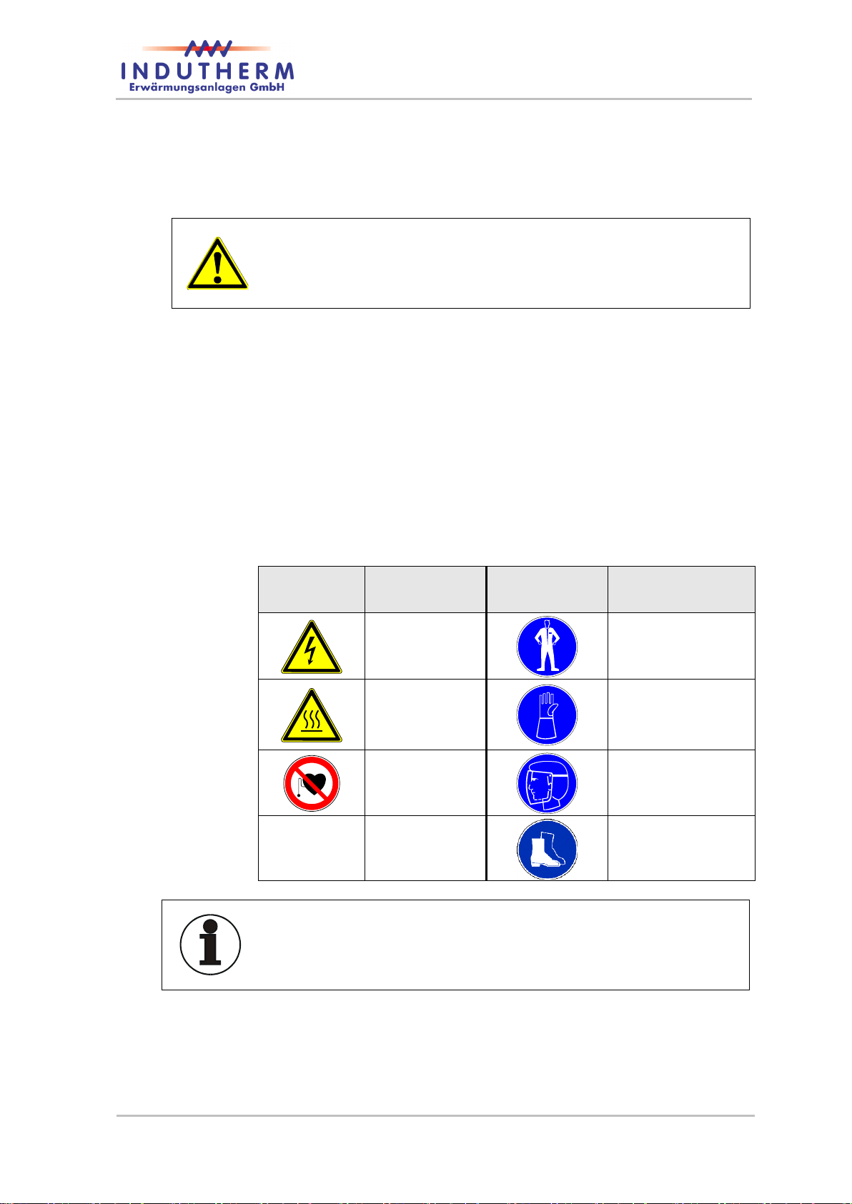
2.4 Safety marking....................................................................2–5
2.5 Safety advices.....................................................................2–6
2.6 Residual risks....................................................................2–10
2.7 Behaviour in an emergency...............................................2–10
3Technical data.....................................................................3–1
4Description of the system ..................................................4–1
4.1 Components of the system..................................................4–1
4.2 Schematic representation....................................................4–2
4.3 Backside connections .........................................................4–5
4.4 Setup of the crucible chamber.............................................4–6
4.5 Additional operating elements.............................................4–7
4.6 Special options..................................................................4–11
4.6.1 Granulation tank................................................................4–11
4.6.2 Hinged window..................................................................4–12
4.6.3 Refill system......................................................................4–13
4.7 Description of function.......................................................4–14
5Transport.............................................................................5–1
6Mounting and commissioning ...........................................6–1
6.1 Safety advices for mounting................................................6–1
6.2 Mounting process................................................................6–1
6.3 Apply supply connections....................................................6–2
6.3.1 Power supply ......................................................................6–2
6.3.2 Cooling water......................................................................6–2
6.3.3 Protective gas.....................................................................6–3
6.3.4 Vacuum for VCC.................................................................6–3

Contents
TechDoku_CC1000_VCC1000_CC3000_VCC3000_GenPM_GB_86025010_86025110.doc
4
6.3.5 Gas outlet ...........................................................................6–3
6.3.6 Vacuumpump (mains socket 16 A) for VCC........................6–3
6.3.7 RS232 for service................................................................6–4
6.3.8 USB socket (universal serial bus) for service ......................6–4
6.3.9 LAN-socket (Local Area Network) for service......................6–4
6.3.10 Internal modem (modem antenna)......................................6–4
7Operation..............................................................................7-5
7.1 Safety advices for operation.................................................7-5
7.2 Changing casting parts ........................................................7-6
7.2.1 Removal...............................................................................7-6
7.2.2 Mounting..............................................................................7-7
7.3 Front panel...........................................................................7-8
7.3.1 LCD screen after mains switch on........................................7-8
7.3.2 CC-Info-page .....................................................................7-10
7.3.3 Predefined casting programs .............................................7-11
7.3.4 System parameter..............................................................7-12
7.3.5 State Level.........................................................................7-13
7.3.6 (V)CC Front panel below display........................................7-14
7.4 Casting...............................................................................7-15
7.4.1 Overview............................................................................7-15
7.4.2 Continuous casting.............................................................7-15
7.5 Granulating ........................................................................7-21
7.6 Casting reports...................................................................7-23
7.7 Error diagnosis...................................................................7-23
7.8 Troubleshooting .................................................................7-24
7.9 Service...............................................................................7-24
8Maintenance.........................................................................8-1
8.1 Safety advices for repair and maintenance...........................8-1
8.2 Maintenance schedule.........................................................8-3
8.3 Repair..................................................................................8-5
9Dismantling and cleaning up .............................................9–1
10 Annexe................................................................................10-1
10.1 List of figures......................................................................10-1
10.2 CE-Declaration of conformity .............................................10-3
10.3 Test result chart.................................................................10-5
10.4 Connection diagrams.........................................................10-6
10.5 Cooling water circuit.........................................................10-10
10.6 Cut drawing VCC .............................................................10-11
10.7 Consumable and spare parts list......................................10-13
10.8 Error and warning messages ...........................................10-15

General
information
TechDoku_CC1000_VCC1000_CC3000_VCC3000_GenPM_GB_86025010_86025110.doc
1–1
1 General information
1.1 Scope of delivery and responsibilities
The continuous casting machine (V)CC1000 or (V)CC3000 is deliv-
ered complete. Please check delivery immediately after receiving the
shipment if there are something missing or possible transport damag-
es. Please tell the faults the shipping agency and your dealer.
1.2 Liability, warranty and guarantee
The company INDUTHERM Erwärmungsanlagen GmbH take liability,
warranty and guarantee according to the legal regulations.
The continuous casting machine is built to be state-of-the-art and in
compliance with the accepted safety regulations. Nevertheless, can
improper installation and non-intended using lead to danger and
damages.
INDUTHERM Erwärmungsanlagen GmbH don’t take liability for dam-
age caused by untrained personnel operating the machine.
For damages because of demonstrably misusing of machine or be-
cause of abnormal behaviour no liability will be taken by IN-
DUTHERM Erwärmungsanlagen GmbH!
INDUTHERM Erwärmungsanlagen GmbH don’t take liability for dam-
ages caused by faulty protection of power supply and/or wrong con-
necting the supplies (protective gas, water, compressed air).
There is no guarantee for consumables by INDUTHERM Erwärmung-
sanlagen GmbH.
Company INDUTHERM Erwärmungsanlagen GmbH cannot and will
not take responsibility for all consequential damages caused by
above mentioned circumstances.
This operating manual is of the technical state at printing date. All
rights reserved regarding technical changings and different equip-
ment.
Damages caused by disregard, wrong interpretation and non-
compliance with specifications in this manual will lead to expiration of
guarantee for this system.
1.3 Responsibility of operating company
The operator must meet with the national accident preventing regula-
tions and technical regulations.
Operating company is allowed to let operate machine by trained and
trustworthy personnel only.
Operating company must make sure the system is supervised when
there is training at this device.
Operating manual must be kept right next to the system.

General
information
TechDoku_CC1000_VCC1000_CC3000_VCC3000_GenPM_GB_86025010_86025110.doc
1–2
Operating company must ensure operating personnel has read and
understood the manual before they are going to use the machine.
Operating company must ensure unauthorized person has no access
to the system.
Maintenance actions may only be done by authorized personnel or by
service technicians from Indutherm.
1.4 EC-conformity
Declaration of European Community conformity is attached to this
manual.
1.5 Observation of the product
The management will provide you with a secure machine at state-of-
the-art.
Please let us know immediately if there are:
failures at safety measurement devices,
failures during production,
modified parameter settings,
difficulties in using the system,
accidents or near accidents and
remarks for improvement of the manual.

Safety
TechDoku_CC1000_VCC1000_CC3000_VCC3000_GenPM_GB_86025010_86025110.doc
2–1
2 Safety
2.1 Intended use
Operational safety of the continuous casting machine is only guaran-
teed at intended use.
The continuous casting machine serves exclusively for melting, pour-
ing and vacuum casting of commercially available precious metals,
copper- and aluminium-alloys or other suitable metals. The specified
temperature ranges must be complied with.
Every other use of the overall plant or parts is considered as not in-
tended.
Unauthorized modifications of the plant are prohibited because of
reasons for safety! CE declaration of conformity expires with modifi-
cation.
Intended use includes reading, knowing and obeying the operating
instructions. That also contains observing of servicing and mainte-
nance regulations.
Set up, operation and maintenance is only allowed to be carried out
by trained qualified personal that has read and understood all docu-
ments.
The plant may affiliate only to the specified media. Supply voltage
and input respectively output pressure have to be observed to the
given device labelling accordingly.
The machine has been developed for use in enclosed spaces and for
the above mentioned application.
Only original INDUTHERM consumables and spare parts are admit-
ted for operation.
It is not allowed to change or vary the system in any way. Technical
changes need explicit written approval of INDUTHERM Erwärmung-
sanlagen GmbH.
The continuous casting machine must not be placed in areas with ex-
plosive atmospheres.
Predictable abuse:
Warming of human body parts on hot surfaces.
Heating and casting of others then the mentioned metals.

Safety
TechDoku_CC1000_VCC1000_CC3000_VCC3000_GenPM_GB_86025010_86025110.doc
2–2
2.2 Demands on staff, duty for utmost care
Work on and with the machine is allowed to be accomplished by
reliable, trained and instructed staff only. Responsibilities for the
separate sections must be regulated clearly which include opera-
tion, preparation, service and repair.
Only authorized personnel may act at the system.
The machine may never be operated by personnel under influence of
reflex diminishing medicine or people not able to work because of ill-
ness or disorder.
Running of the system must be always supervised by trained staff.
Personnel which must be trained und introduced to this job or during
vocational training may work only under permanent observation of a
person experienced with the machine.
Work on the electrical equipment is only allowed for workers skilled in
the field of electricity.
The instruction manual must be freely disposable at the location of
the system. The employees should know the storage place.
Every person working at the system must read and apply the instruc-
tion manual especially the safety advices. The personnel must read
and understand the chapters referring to safety aspects for the partic-
ularly components of the machine. Please read before beginning the
work.
Please control the personnel for paying attention to all facts of safety
and danger prevention.
2.3 Protective measures
This operator’s guide contains all important advices to operate the
system secure.
Basic prerequisite for safe dealing and trouble-free running of this
system is the knowledge of fundamental safety advices and industrial
safety rules.
In commercial facilities you have to regard the accident prevention
regulations of the professional association for electrical systems and
tools.
When operating the system escape gases / vapours. These are con-
sumable parts dependent applications you use and the molten mate-
rial. The plant operator must provide a suitable on site and the current
standards and laws appropriate exhaust system.
The internal regulations of industrial safety are to be observed.

Safety
TechDoku_CC1000_VCC1000_CC3000_VCC3000_GenPM_GB_86025010_86025110.doc
2–3
2.3.1 Concept of safety
Objective is the safety:
of the staff against injuries;
of the system against damage or standstill and
of the environment against endangering.
The list of actions taken:
deployment of protective equipment like covers and main-switch
with emergency stop function,
safety switch that is used to ensure that the plant can be operated
only with the swivelled vacuum pressure casting tank;
water-cooled inductor housing,
duty of wearing personal protective equipment (PPE),
affix safety markings on the installation,
create safety advices in the manual.
2.3.2 Protective gear
Protective gear (PPE) includes:
heat-resistant clothes,
heat-resistant, closed shoes,
heat-resistant protective gauntlets protecting artery and
face guard.
Caution!
Wear always for every process step the right protective gear.
2.3.3 Safety equipment
The safety of the machine is only guaranteed if all safety equipment is
proper installed and working proper. Don’t use the system without the
safety equipment!
Disassembling safety equipment is only allowed with locked main-
switch. Install every part of the safety equipment after repair. Perfect
function must be checked.
Caution!
Safety equipment protect from unintentional access of the staff to
danger spots. They prevent possible injuries. Never manipulate the
safety devices!

Safety
TechDoku_CC1000_VCC1000_CC3000_VCC3000_GenPM_GB_86025010_86025110.doc
2–4
2.3.4 Main switch with emergency stop function
It is allowed to start the machine or operation only with proper emer-
gency stop function.
Caution!
With the emergency stop function you can stop the machine in criti-
cal moments of health hazard. You help to diminish potential con-
sequences of injury.
> Don’t manipulate the emergency stop equipment.
> Don’t obstruct the way to the emergency stop equipment.
2.3.5 Safety markings on the unit
A necessary condition for safe dealing with and undisturbed running
of the machine is the knowledge of safety instructions and industrial
safety regulations.
On the front of the machine casing the following safety markings are
attached.
safety
marking
meaning
safety
marking
meaning
warning of dan-
gerous electrical
voltages
wear heat resistant
safety clothing
warning on hot
surfaces
wear heat resistant
protective gauntlet
gloves protecting
artery
forbidden for
persons with
pacemaker
wear face guard
wear protective
shoes
Advice
Keep the safety markings always clean. Replace the markings if they
aren’t recognizable. Observe the warnings and commands. Don’t
expose yourself careless to dangerous situations.

Safety
TechDoku_CC1000_VCC1000_CC3000_VCC3000_GenPM_GB_86025010_86025110.doc
2–5
2.4 Safety marking
The following signal words are used in this document which are asso-
ciated with safety markings for presentation of possible dangerous
situations.
Danger!
Death, serious body injury or substantial property damage will result
if proper precautions are not taken.
Warning!
Death, serious injury or substantial property damage can result, if
proper precautions are not taken.
Careful!
Minor personal injury can result if proper precautions are not taken.
Attention!
Property damage can result, if proper precautions are not taken.
Information/advice
Here you get information and advices to carry out the following activi-
ties effective and safe.

Safety
TechDoku_CC1000_VCC1000_CC3000_VCC3000_GenPM_GB_86025010_86025110.doc
2–6
2.5 Safety advices
Check always the condition of the system before you switch on the
system. Examine the supply pipes and insulations if there are leaks
and damages. Operate the system only if it is in proper and faultless
shape.
Operate the system never:
if there are malfunctions,
if it is showing damage or
after heavy transportation stress.
The system must be constantly controlled when running to be able to
recognize and avoid dangerous situations. The system may not run if
it is unsupervised.
Do never change, remove or close the safety valves inside the ma-
chine.
Danger!
Danger to life because of strong electromagnetic fields
(induction). For persons with pacemaker it is not allowed
to approach or to be near to the machine.
Warning!
Risk of burning on hot surfaces and hot metal
(until ~ 1500 °C). Wear always personal protective
equipment when you work with the machine.
Utmost caution during using graphite crucibles and
graphite moulds. The heat of these parts is only visible
when the temperatures are over 500 °C.
Warning!
Maintenance and servicing of the machine only when the system is
disconnected from the mains supply (Pull out mains plug).
Advice!
Don’t disconnect mains plug, while machine is running or in standby.
Switch off for pulling out or putting in mains plug.

Safety
TechDoku_CC1000_VCC1000_CC3000_VCC3000_GenPM_GB_86025010_86025110.doc
2–7
Danger!
Risk of burns. If metal is melted without the supply of protective gas,
can cause a flash fire or explosion when opening the bell.
Melt at temperatures above 500 °C always with protective gas. Use
as a protective gas exclusively argon or nitrogen.
Danger!
Danger because of touching parts conducting voltage.
Work on the electrical equipment is only allowed for au-
thorized qualified staff.
Access to the electrical distribution box is only allowed
for authorized qualified staff with tool.
Work on the electrical equipment is only allowed when
the system is disconnected from power supply (pull out
power plug).
The capacitors can retain their charge even after de-
activation of the system.
Keep the housing of the continuous casting machine
closed continually.
No work must be carried out on parts conducting high
voltage.
Remove loose connections.
Replace immediately damaged scorched or slightly
burned cables. Perform work only when mains plug is
pulled out.
Cables may not wedge in or rather squeezed. Cables
have to be laid in a way that they not become a trip-
ping hazard or can be not damaged.
Danger!
Threat of health injury by escape of medias from damaged hoses.
Danger of system damages.
Remove loose connections. Replace damaged hoses immediate-
ly. Perform work only when mains plug is pulled out.
Hoses may not wedge in or rather squeezed. Hoses have to be
laid in a way that they not become a tripping hazard or can be not
damaged.

Safety
TechDoku_CC1000_VCC1000_CC3000_VCC3000_GenPM_GB_86025010_86025110.doc
2–8
Danger!
Burning risk by leaking hot metal at protective gas failure.
When protective gas failure of the sealing rod can no longer close
properly. Through a check valve, the pressure is maintained in the
lock cylinder. When pneumatically powered units are operated after
a compressed air failure, molten metal can freely leak through the
die.
Press after a protective gas, no pneumatic units (e.g.: cylinder).
Warning!
Bodily harm by burning.
Before you switch on the system fix the protective cover in front the
die cooler. An absence of the protective cover will lead to danger
during casting of
burns if liquid metal squirts,
burns on hot surfaces and
squeezing the hand between the pressing rollers.
Warning!
Danger of explosion.
Dripping of liquid metal can’t be excluded.
Set up a water-filled steel tub below the casting device.
When aluminium is poured, the steel tub must be filled with sand. If
the tub filled with water then exists danger of explosion.
The floor beneath the system must be made of non-flammable mate-
rial. As well there must not be stored inflammable materials within a
radius of 5 metres.
Attention!
If crucible temperature is over 100 °C the cooling water supply must
be switched on. If it is not turned on, the inductor will be destroyed. If
cooling water supply fails, the heating system immediately is turned
off. Inspect the system for damage before putting back into operation
again.
Warning!
Burning hazard because of leaking molten metal.
The system must not be operated without a sealing rod for security
reasons.
The tip of the sealing rod must stay in the centre of the pouring hole
even when sealing-rod is open.
With built-in and closed sealing rod the according cylinder must have
a gap to the lower end stop or the pouring hole is no longer proper
sealed.

Safety
TechDoku_CC1000_VCC1000_CC3000_VCC3000_GenPM_GB_86025010_86025110.doc
2–9
Danger!
Lethal injuries happen because of false transport by forklift truck.
Pay attention of the right attachment of the means of transporta-
tion, otherwise the system can fall from forklift truck. The system
must be lifted from the side only, because the centre of gravity is
located in front and towards the upper third of the machine.
With too small dimensioned or forks adjusted too narrowly there
is danger for the system to fall from the means of transportation.
Wear appropriate personal protective equipment (PPE).
Move the system only by skilled personnel qualified for transpor-
tation jobs.
For damages resulting from non-compliance of regulations in transit
there is no assertion possible for warranty claims.
Warning!
Health risk because of lifting heavy weight.
Lift and transport the granulating tank only by two persons. Don’t try
to transport the tank by yourself. There is danger of permanently
healthy damages because of physical overload.
Warning!
Risk of injury.
Make pressure leading system parts depressurized before you carry
out servicing.
Warning!
Risk of slip on the floor around the installation in case someone had
spilled lubricant or solvent.
Clean the floor from dirt immediately! Dispose cleaning tissues in the
particular collecting boxes.
Caution!
Observe regulations for the mains supply written from the
responsible electric power supply company, the associa-
tion VDE and the local electric power station.
Inappropriate connecting can lead to injuries and dam-
ages of the machine.

Safety
TechDoku_CC1000_VCC1000_CC3000_VCC3000_GenPM_GB_86025010_86025110.doc
2–10
Caution!
Danger for health because of inhalation of fibre particles.
Store crucible shield and insulation in dustproof package.
Remove the material just before installation.
Don’t shatter crucible shield and insulation.
Pack the materials immediately after removal dustproof and dis-
pose the materials in this packaging
2.6 Residual risks
risk characterisation
risk reduction
Health risk for persons with
cardiac pacemaker who ap-
proach the running system.
Instruct people.
Burn injury on hot surfaces or
hot molten metal.
Teach people. Wear personal pro-
tective equipment.
Danger of explosion because of
dripping of liquid metal in a wa-
ter filled steel tub during melting
of aluminium or aluminium-
alloys.
Fill the tub with sand.
Jet flame or explosion when
opening the lid of the melting
chamber in case of melting
without protective gas.
Always melt with protective gas
at temperatures above 500 °C.
Tilting and toppling of the sys-
tem due to improper transporta-
tion.
Consider shipping instructions.
2.7 Behaviour in an emergency
The personnel working at the facility must be trained about the behav-
iour in an emergency.
All persons who are working with the machine must be informed of
the possibility of rapid standstill of the plant.

Technical
data
TechDoku_CC1000_VCC1000_CC3000_VCC3000_GenPM_GB_86025010_86025110.doc
3–1
3 Technical data
(V)CC1000
(V)CC3000
Crucible diameter in mm
Crucible volume in cm³ (1)
1500
3400
Material weight
15 kg Ag, 22 kg Au 18 kt
30 kg Ag, 51 kg Au 18 kt
Max. Die Ø in mm
70
110
Outside dimensions die in
mm
120x30
160x40
Wire Ø in mm (1)
max. 40
max 5 x Ø 15 oder 1x 40
Sheet L x B in mm (1)
40x40 with round die or max.
100 x 10 with rectangular die
max. 130 x 12
Tube Ø in mm (1)
max.50
max. 50
Power in kW
20
30
Mains supply
3 x 400 V,50 or 60 Hz
Fuse protection A
32
44 (external 63)
Short circuit current
max. 5.0 kA
max. 10 kA
Thermocouple
Typ K (NiCr-Ni; max. 1200 °C) oder
Typ S (PtRh-Pt; max. 1500 °C) (with other insulations)
Cooling water supply
2 x Ø 13 mm, fittings with1/4” thread (Øa 13.2 mm)
2.5 - 5 bar, min. 400 l/h, max. 6 °dH
water filter for suspended particles
Cooling water recoil
pressureless
Cooling water entry tem-
perature in °C
15 –25
Ambient temperature in °C
10 –35
Relative atmospheric hu-
midity
20 - 80 %
Protective gas supply
1 x Ø 6 mm, fittings with ¼“ thread (Øa 13.2 mm)
max. 8 bar, pure N2, pure Ar (at least 99,9 % purity) or forming gas
90/10, estimated consumption 4-6 l/min
Vacuum supply (VCC)
1x Ø 13 mm, fittings with ¼”‘ thread (Øa 13.2 mm),
0-20 mbar absolute, at least 21 m³/h
Weight in kg
220
280
Dimensions in mm
(width x depth x height)
700 x 1000 x 1870
800 x 1100 x 2000
Maximum melting temper-
ature in °C
1500 (with special insulations)
Options
Granulating tank
Cutting device
Sheet- and wire dies
Noise emission
75 dB (A)
(1) optional changing

System
description
TechDoku_CC1000_VCC1000_CC3000_VCC3000_GenPM_GB_86025010_86025110.doc
4–1
4 Description of the system
4.1 Components of the system
The system consists of several modules are assembled in one hous-
ing.
Inside the housing there are:
mains cable and mains filter,
microprocessor controlled induction generator PM-type,
middle-frequency transformer,
oscillating circuit capacities,
pneumatic (magnet-) valves,
pressure regulator for pressure of the sealing rod cylinder and
pressure regulator for protective gas.
The front plate contains:
front panel for control of the casting process and
printer for output of a casting report.
To the melting system belongs:
inductor housing, water cooled with inductor, crucible, insulations,
sealing rod unit, thermocouple,
bell hinged, water-cooled and
die and die cooler,
drawing device,
cutting device (option),
bending unit (option) and
granulating tank (option).

System
description
TechDoku_CC1000_VCC1000_CC3000_VCC3000_GenPM_GB_86025010_86025110.doc
4–2
4.2 Schematic representation
Figure 1: overall view
1
2
8
3
4
9
5
10
6
11
7
12
13
pos.
designation
function
1
bell with window
Closing the inductor housing.
2
inductor housing (cruci-
ble chamber)
In the inductor housing are:
Induction coil
crucible
insulation and
crucible press plate.
3
die insulation
Heat insulation material.
4
die cooler and die
There are different shapes (round and rectangular) of open die
cooler (CC) and vacuum sealed die cooler (VCC).
5
Secondary chiller
Additional water cooling.

System
description
TechDoku_CC1000_VCC1000_CC3000_VCC3000_GenPM_GB_86025010_86025110.doc
4–3
pos.
designation
function
6
drawing device
Drawing device for continuous moving down of metal. Here in
picture quattro drive
7
water drain
For let out condensed water in machine.
8
front panel
Control the process of the system. See chapter 7.4.
9
printer
Enables printing of casting report, list of program parameter or full
systemparameter overview.
10
press rolls
The press rolls are pressed with the press cylinder to the starter
bar/drawing rolls
11
press cylinder
This cylinder holds the press rolls tight to the blank (casting re-
sult).
12
light
White light for checking the casted piece right after the die.
13
Mains switch with
emergency stop func-
tion
Switch on and off the continuous casting machine. Immediate
interrupt of power in emergency.
14
Slide for closing the die
(option)
With this slide the die will be closed after the casting process.
When there is no slide you should close the die with the starter
bar.
This manual suits for next models
3
Table of contents
Other Indutherm Industrial Equipment manuals