INELCO GRIDERS Ultima-Tig-Cut Installation and operating instructions

INELCO GRINDERS A/S ULTIMA-TIG-CUT
Inelco Grinders A/S, Industrivej 3, DK-9690 Fjerritslev, Denmark 2
Translation of the original EU statement of compliance
Manufacturer: INELCO GRINDERS A/S
Industrivej 3, 9690 Fjerritslev, Denmark
Phone + 45 96 50 62 33, Fax. + 45 96 50 62 3
SE/VAT No: DK 32652964
E-mail: info@inelco-grinders.com
hereby declare that
Machine: ULTIMA-TIG-CUT
Type: UT110
Serial no.: see page 2
Year of production: see page 2
is produced in accordance with the provisions of the Commission’s Directive
on harmonization of national legislation’s on machinery 2006/42/EU, EMC-directive
2014/30/EU and RoHS2 directive 2011/65/EU.
Authorized to create the technical file: Anders Thy, Industrivej 3, DK-9690 Fjerritslev
ULTIMA-TIG-CUT is developed and produced according to the following international
norms:
EN 12100:2010, EN 50581:2012, EN 61029-1: 2009+A11,
EN 61000-6-4: 2005, EN 61000-6-2: 2007
Person responsible: Name: Anders Thy
Date: 01.12.2019
Signed: ____________________

INELCO GRINDERS A/S ULTIMA-TIG-CUT
Inelco Grinders A/S, Industrivej 3, DK-9690 Fjerritslev, Denmark 3
Contents
1. General machine description................................................................................................4
2. What is included...................................................................................................................4
3. Operational elements...........................................................................................................5
4. Initial operation and transport...............................................................................................5
5. Safety procedures................................................................................................................6
6. Fastening of the electrode in the electrode holder................................................................6
7. Setting the grinding angle.....................................................................................................6
8. Electrode cutting ..................................................................................................................7
9. Maintenance ........................................................................................................................9
10. Replacement of the grinding disc .......................................................................................11
11. Replacement of the cutting disc .........................................................................................11
12. Field of application.............................................................................................................12
13. Technical specifications .....................................................................................................12
14. Training..............................................................................................................................12
15. Safety data sheet for grinding fluid.....................................................................................12
16. Spare parts overview..........................................................................................................13
17. Working table.....................................................................................................................16
18. Accessories........................................................................................................................17
IMPORTANT SAFETY INSTRUCTIONS
When installing and operating the machine the safety rules
enclosed
SUPPLIER’S DIRECTIONS
should be read and strictly observed.
This instruction manual and the accompanying supplier’s
instruction for use must be accessible at all times to staff engaged
in the installation, operation and maintenance of the machine.
DISPOSAL
Do not dispose electrical equipment in your ordinary waste disposal. The European
guideline 2012/19/EU on Electrical Equipment Waste and its implementation in national
laws requires such used equipment to be separately collected and recycled in an
environmentally friendly manner

INELCO GRINDERS A/S ULTIMA-TIG-CUT
Inelco Grinders A/S, Industrivej 3, DK-9690 Fjerritslev, Denmark 4
1. General machine description
ULTIMA-TIG-CUT is a patented grinder and cutting devise with diamond discs for wet grinding and
cutting of tungsten electrodes for TIG welding. It is very easy and safe to use.
The diamond disc grinds the tungsten electrodes correctly in the longitudinal direction of the electrode,
and the variable angle adjustment allows you, not only to grind in the right angle, but also to grind the
tip flat, if needed.
Cutting function with the diamond-cutting disc, gives an exact and sharp cut of the tungsten electrode
in the precise length, without any risk of damaging the electrode.
The grinding liquid in the closed grinding and cutting chambers ensures that no harmful dust particles
slips out into the surroundings. The cooling effect of the grinding liquid also mean, that there are no
discoloration of the tungsten electrode due to heat.
The harmful grinding dust is collected automatically in the special dust collector and hence can be
disposed correctly.
The included electrode holder and electrode clamps, in combination with stick-out adjustment, reduces
the waste of electrodes, and ensures a uniform grinding result at each grinding.
The ULTIMA-TIG-CUT can be used in a room with an ambient temperature of 0° C to +40° and a
relative humidity of up to 50% at 40° C and 90% at 20° C. The machine are tested acc. protection class
IP21.
2. What is included
Upon reception und unpacking please, check that the following items are included in the package:
ULTIMA-TIG-CUT machine
2 dust collectors with liquid (Item No. 75494500)
2 x 250 ml bottles off grinding/cutting liquid (Item No. 75491200)
Tungsten electrode holder (Item No. 75520023)
Pickup (Item NO. 75500170)
Pickup Release (Item no. 75520021)
Electrode clamps for Ø1,6 - Ø2,4 and Ø3,2 mm
Clamps for cutting Ø1,6 - Ø2,4 and Ø3,2 mm
2 x Tip collector (Item No.75520049+75520050)
Worktable, incl. bolts and nuts for mounting

INELCO GRINDERS A/S ULTIMA-TIG-CUT
Inelco Grinders A/S, Industrivej 3, DK-9690 Fjerritslev, Denmark 5
3. Operational elements
1. Power Switch
2. Degree scale
3. Electrode holder
4. Tightening screw to flatten the tip of the electrode
5. Stick-out adjustment
6. Length adjustment for cutting
7. Pickup
8. Tip collectors
9. Pickup release
10. Reset button
11. LED
12. Handle for cutting
4. Initial operation and transport
Remove the protective foil on the enclosed worktable and mount the worktable as shown in the
drawing in the back of this manual. Fasten the grinder on the worktable and place it securely on a
workbench or table.
IMPORTANT: The ULTIMA-TIG-CUT cannot run without grinding liquid!
The ULTIMA-TIG-CUT grinder does not contain grinding liquid on delivery. Before starting the
machine the first time, mount the supplied dust collectors and fill extra grinding liquid from the bottle
provided through the tube until the correct liquid level has been reached (please see mark on the
inspection cover frame). (See drawing and photos in the back of this manual)
Check that the switch is in the OFF position. (“O” on the switch)
Connect the machine to the mains voltage specified on the nameplate.
IMPORTANT: Only use single-phase power supply outlet WITH an earth connection.
12
4 2 6
1
3
5
9
8
7
11
10

INELCO GRINDERS A/S ULTIMA-TIG-CUT
Inelco Grinders A/S, Industrivej 3, DK-9690 Fjerritslev, Denmark 6
5. Safety procedures
Never use the product if the grinding disc is damaged
Use only diamond discs recommended by Inelco Grinders A/S
Use the product only when all parts of the chamber is mounted
Use only the grinder with EP770 grinding liquid from Inelco Grinders A/S
Only grind Tungsten electrodes with electrode holder
Always use an appropriate size clamp to the electrode for grinding.
6. Fastening of the electrode in the electrode holder
Select the size of the electrode clamp that match the diameter of the electrode and mount it loosely
in the electrode holder. Then insert the electrode into the clamp, so that approximately 20 mm of the
electrode is sticking out of the clamp. Tighten the clamp with your fingers, but not so tightened that
the electrode cannot slide in the clamp.
Insert the electrode with the electrode holder into the stick-out setting (10),
placed below on the right front side of the grinding (see picture), until it stops.
Tighten the electrode with a smooth turn of the electrode holder clockwise.
Only fasten the electrode as tight, as it does not slide in the electrode clamp.
If the electrode is too tight fasten, you risk damage of the clamp.
On the back of the stick-out adjustment, there is a regulator screw (see
picture), which can be adjusted to determine the length of the electrode
sticking out of the clamp. The manufacturer has set the regulation screw to
grind approx. 0,3 mm in order to obtain the highest number of grindings per
electrode as possible.
This means, that you can re-grind the electrode up to 450 times. It is
necessary to adjust the stick-out as the diamond wheel wears down.
It is often not necessary to break off metal drops on the electrode before grinding. The metal drops
do not melt together with the electrode; the grinding process will remove them.
7. Setting the grinding angle
Adjust the grinding angle by placing the cursor (1) at the desired grinding
angle. Tighten the electrode guide by tightening the screw (2).
Note: the grinding angle equals half the tip angle!
2
1

INELCO GRINDERS A/S ULTIMA-TIG-CUT
Inelco Grinders A/S, Industrivej 3, DK-9690 Fjerritslev, Denmark 7
After the tungsten electrode is inserted in the electrode holder, it is inserted in
the angle adjust unit until the electrode almost touches the diamond disc. Start
the machine at the on/off switch and turn the electrode holder in a calm and
steady pace andwith light pressure until the electrode holder cannotgo further
in. Keep turning the electrode holder for at least five rounds to get the best
possible grinding result.
It is not necessary to press the electrode hard against the diamond
wheel, a light pressure and the rotation of the grinding disc is sufficient
to grind the electrode.
Pull the electrode holder back a little, so that the electrode does not touch the grinding disc. Turn off
the grinder and pull out the electrode holder after the grinder has stopped turning.
Removed the electrode from the electrode holder by re-inserting the electrode into the stick-out
adjustment and turn it counterclockwise. Then pull out the electrode.
To create a flat tip on the electrode after grinding:
Setting grinding angle to 90° (while grinder is turned off)
Put the electrode holder with the electrode in the angle adjustment again
Turn the tightening screw on the angle setting down until you feel the tip of the electrode
touches the grinding wheel.
Then turn the tightening screw down. A point on the brass bearing on top of the screw
corresponds to remove 0.1 mm off the tip.
Pull the electrode away from the grinding disc.
Start the grinder and gently push down the electrode holder in a turning movement and
the tip is flattened.
Turn off the grinder and pull out the electrode holder.
8. Electrode cutting
Turn off the machine after grinding the electrode.
Loosen the electrode in the stick-out (1) on the cutting
console, pull out the electrode and tighten the electrode clamp,
using your fingers.
Set the cutting length, using the screw (2) for length stop
(4). The cutting length is the same as the distance between
the cutter console (3) and the length stop (4). Measure the
cutting length, using a caliper (not included). The cutting length
can be also adjusted by turning the Brass pin (5) on the
length stop.
1
2
4
3
5
INELCO GRINDERS A/S ULTIMA-TIG-CUT
Inelco Grinders A/S, Industrivej 3, DK-9690 Fjerritslev, Denmark 8
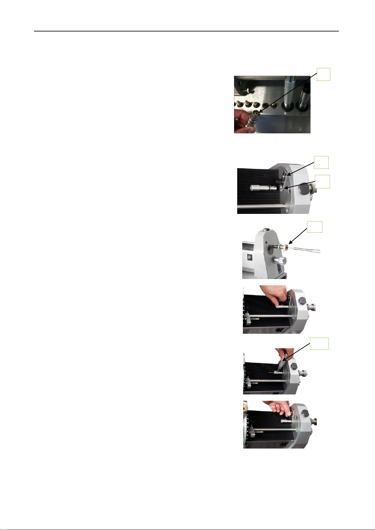
Place the electrode holder in the stick-out on the cutting console and tighten the
electrode by turning the electrode holder.
Mount the clamp for the correct electrode diameter in the
Pickup (6) by pushing in the back part of the Pickup
and using your fingers to screw the clamp in. Please note
that the clamps for the Pickup are different (flat) from the
clamps for the electrode holder.
Warning: If the clamps for the electrode holder are used
in the Pickup, the clamps will be damaged by the cutting disc.
Mount the Pickup in the hole on the back of the cutting
console (7). Make sure the Catch for Pickup (8)
is holding the Pickup in place.
Place the electrode holder in the electrode guide (9),
and push it in, while releasing the Pickup with your fingers
(for short electrodes),
or with the Pickup release (10) (for long electrodes)
where the electrode pass through the Pickup, ensuring
that the electrode tip is secured in the Pickup.
After the electrode holder is in place, tighten the clamp for
the Pickup to ensure that the Pickup is kept in place during
cutting.
To avoid grinding liquid splashing out of the electrode guide on the
grinding part, the Pickup release (10) can be placed in the
electrode guide.
6
8
7
9
10

INELCO GRINDERS A/S ULTIMA-TIG-CUT
Inelco Grinders A/S, Industrivej 3, DK-9690 Fjerritslev, Denmark 9
Turn on the machine.
Push in the handle (11) and slowly turn it clockwise
until the electrode is completely cut through and the handle
reaches the stop. Turn the handle back slowly until it comes
back out. To minimize burrs on the electrode tip, hold the
electrode holder tight during cutting, using the other hand.
Important: Turn the handle all the way to the right to make
sure that the electrode is cut through.
Turn off the machine.
Loosen the screw for the Clamp, release the clamp and remove
the Pickup.
Remove the burrs on the electrode tip, using the Deburring
block (12) before removing the tip from the Pickup.
The cutting length can be fine adjusted using the tightening screw on
the electrode guide. One round equals 1 mm. This adjustment is also
needed when long electrode clamps are used in the electrode holder,
when grinding and cutting short electrodes, to prevent the cutting disc
from damaging the electrode clamp.
For cutting off a damaged tip on an electrode, which has not been
grinded, use one of the supplied tip collectors instead of the Pickup
module. Choose the tip collector suitable for the diameter of the
electrode.
9. Maintenance
The ULTIMA-TIG-CUT must always have sufficient grinding liquid, in order to
secure an optimum collection of dust and cooling of the grinding process. A mark
on the glass frame of the grinding chamber indicate the correct amount of grinding
liquid (measured while the grinder is off). Check amount of grinding liquid regularly
and top up if necessary. To ensure a long service life of the grinder and the
diamond discs use original ULTIMA-TIG- CUT grinding liquid.
Replaced the grinding fluid heavily contaminated with dust.
11
12

INELCO GRINDERS A/S ULTIMA-TIG-CUT
Inelco Grinders A/S, Industrivej 3, DK-9690 Fjerritslev, Denmark 10
Deposit grinding fluid and/or containers containing dust in accordance with national
regulations depending on the grinding dust content. Please see the data sheet of the selected
electrodes.
Daily Inspection
In order to secure free movement of the angle adjustment, move it all the way back and forward every
day. Not following this procedure, the machine will gradually collect dust inside the grinding chamber,
and as a result, the angle setting will be stuck and it is impossible to change the grinding disc. Also
make a daily check of the free movement of the arm for cutting.
Monthly/1000 grind service
Clean the grinding chamber when the LED lights yellow or at least once every
month following these steps:
1. Drain out the grinding fluid through the hose into an empty container.
2. Set the angle adjustment to 90°.
3. Remove the two screws, the frame and the inspection cover.
4. Wipe off thegrinding chamber with a cloth or paper towel. Eventually
remaining stuck dust can carefully be scraped off.
5. Mount the inspection cover and frame and top up with grinding liquid.
6. Reset the service counter by turning on the grinder and pressing and
holding the pushbutton for 3 seconds.
If the grinding liquid does not come out of the hose, it may be due to grinding
dust inside the grinding chamber blocking the hole. To get the grinding dust
away, press a little air or grinding fluid through the hose, using the grinding
fluid bottle.
Quarterly/5000 grind service
When the LED blinks yellow or at least once every three months clean the
inside of the grinding chamber following these steps:
The power to the ULTIMA-TIG must be turned off –pull out the plug.
1. Drain out the grinding fluid through the hose into an empty container.
2. Set the angle adjustment to 90°.
3. Remove the dust collector under the grinding chamber.
4. Place a support under the motor housing, ~20mm tall. Remove the three torx screws on
the back of the grinding chamber and the two bolts under the table. Now you can remove
the grinding chamber from the motor housing.
5. Clean out the grinding dust inside the grinding chamber. Dismantle the angle adjust unit if
necessary. Make sure the angle adjust unit can slide smoothly all the way back and forth.
6. When assembling the parts add bearing grease to all moving parts, screws and gaskets
except for the Inspection cover mounting.
7. Check the O-ring on the backplate before mounting the grinding chamber.
8. Mount and tighten the torx screws and the two bolts.
9. Carefully check the dust collector before mounting and top up with new grinding fluid.
10. Reset the service counter by turning on the grinder and pressing and holding the
pushbutton for 5 seconds.
Clean the Ultima-TIG-CUT thoroughly each time the grinding disc is replaced, when the dust
collector is full, or earlier if necessary. Perform cleaning as mentioned above.
Clean the Cutter module on the inside when changing the cutting disc. (See section 11)

INELCO GRINDERS A/S ULTIMA-TIG-CUT
Inelco Grinders A/S, Industrivej 3, DK-9690 Fjerritslev, Denmark 11
Please ensure that the person cleaning the ULTIMA-TIG-CUT wears the appropriate safety gear e.g.
rubber gloves and protection glasses.
It can be difficult to remove the grinding dust from the aluminum parts without damaging the parts;
boiling hot water is an effective way to dissolve the grinding dust. Do not use chemicals, solvents or
high pressure cleaning.
Check the main cable regularly. Only qualified personnel must replace it. If necessary, contact Inelco
Grinders A/S or your local distributer for service.
10. Replacement of the grinding disc
Please follow the procedure below when disassembling the machine:
The power to the ULTIMA-TIG-CUT must be turned off –pull out the plug.
Tap of the grinding liquid from the grinding chamber; remove the two screws, the cover frame and
the plastic inspection cover. Set the grinding angle at 90°.The disc is now assessable. Unlock the
center screw (Note: Left-hand screw). Remove the U-wheel and the Grinding disc and mount a new
grinding disc.
11. Replacement of the cutting disc
Empty the liquid from the chamber and remove the dust collector.
Loosen the cutter module from the working table.
Remove the three screws from the back of the cutting house, and pull the
house away from the back plate.
Remove the four small
screws that holds the
cutting disc and remove the
cutting disc.
Replace the new cutting disc and mount the Plastic cogwheel, Washer and the screws again.
Clean all parts with water and make sure to collect this in the return bottle. Deposit the wastewater as
described under section 9. 20171448/16246
Apply grease on the inside of the console and on the edge of the rear plate where the two parts
meet each other. This facilitates the remounting and contributes to reseal the device.
Push the house back on to the rear plate and be careful to position the bar with the two wheels so
that the teeth on the plastic wheels fit on to the teeth of the cogwheel on the motor axel.

INELCO GRINDERS A/S ULTIMA-TIG-CUT
Inelco Grinders A/S, Industrivej 3, DK-9690 Fjerritslev, Denmark 12
Also, make sure that the seal on the rear plate is correctly in place and not twisted while sliding the
house into place. Mount the three screws to fasten the house to the rear plate, mount the dust
collector and top up with additional liquid. The correct level of liquid is marked by (~~~) on the lover
square inspection cover.
12. Field of application
Only use the devise for grinding and cutting of tungsten electrodes.
13. Technical specifications
The Ultima-TIG-CUT are covered by Wolfram grinder patent application No. 95942059.7
Current class: (single-phase alternating current) 1x120V or 1x220-240V AC. Depending on themodel.
Please see the nameplate on the grinder for the power supply.
Safety protected with protective earth. Directive 2006/95/EU
14. Training
No special education is required to operate the ULTIMA-TIG-CUT. However, persons who are to
operate the ULTIMA-TIG machine should read the instruction manual thoroughly beforehand and to
have received basic training in use of the machine.
15. Safety data sheet for grinding fluid
Please go to the following link http://www.inelco-grinders.com/specifications to find the MSDS data
sheet for the grinding fluid.
INELCO GRINDERS A/S ULTIMA-TIG-CUT
Inelco Grinders A/S, Industrivej 3, DK-9690 Fjerritslev, Denmark 13
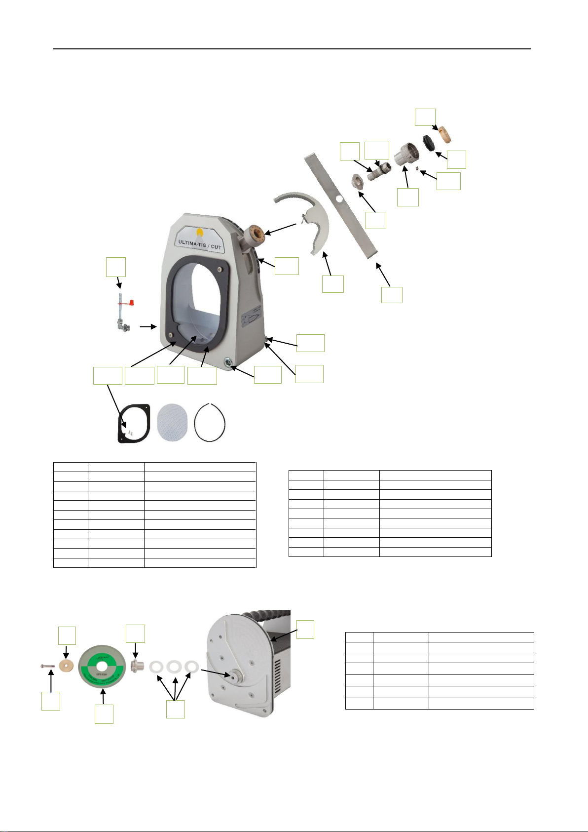
16. Spare parts overview
Pos.
Item No.
Description
1
75522500
Drain/filling pipe
2a
44490901
Frame
2b
44490700
Plastic Inspection Cover
2c
44520009
Packing ring f. insp.cover
2d
40320410
Retaining screw M4x10
3
75520001
Angle adjust unit
4
44520007
Metal strip
5
44520008
Degree scale bush
6
44520022
Stretching screw
6a
44470312
O-ring ø12x2
Pos.
Item No.
Description
7
44520004
Tightening screw
7a
40310404
Pointed screw M4x6
8
44470124
Rubber pack
9
44520027
Bronze bearing Outward
10
44520024
Screw f. stick-out
11
40040670
Screw M6x70
12
44520028
Spring f. stick-out
13
62189220
Degree scale
Pos.
Item No.
Description
1
44520017
Bush f. wheel
2
41530530
U-wheell UT
3
44520018
Weather ring f. bush (set)
4
44490512
Diamond disc
5
44496525
Screw M5 lefthand
6
44520010
Packing ring f. rear plate
3
4
6
6a
a
8
9
7a
a
2a
2c
1
5
7
2b
10
11
12
13
2d
3
1
2
4
5
6
INELCO GRINDERS A/S ULTIMA-TIG-CUT
Inelco Grinders A/S, Industrivej 3, DK-9690 Fjerritslev, Denmark 14
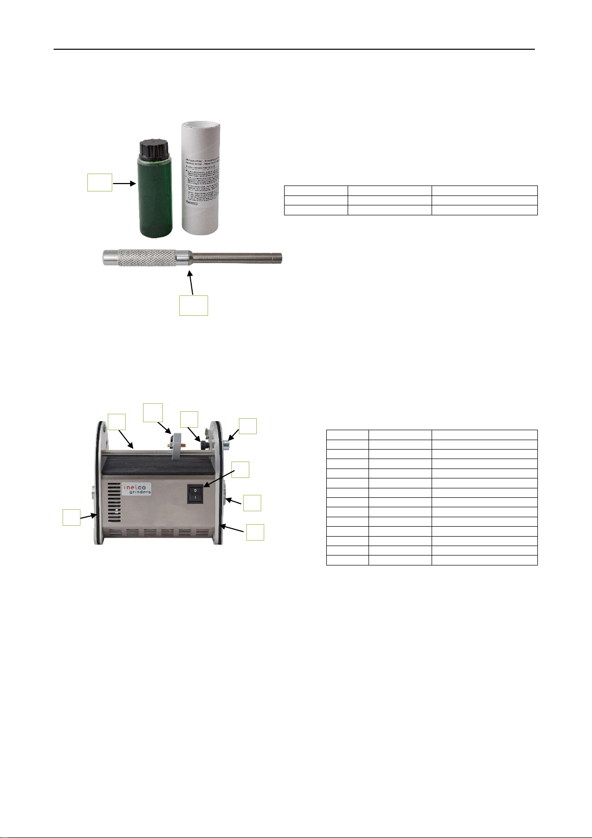
Pos.
Item No.
Description
1
75520023
Electrode holder
2
75494500
Liquid container W95/1-45
Pos.
Item No.
Description
1
44520106
Rod for length stop
2a
44520107
Arm for length stop
2b
44520109
Brass pin f. length stop
2c
41110605
Nut M6
2d
44493210
Screw BT16P M4x16
3a
44520112
Screw for pickup
3b
44520045
Catch for pickup
3c
40110511
Screw M4x12
3d
41512304
Plate disc rustproof ø4
4
17110027
Power switch
5
44520130
Stick-out bolt cut
6
44520103
Transmission cogwheel
7
44520010
Packing ring f. rear plate
1
2
1
2
3
4
5
6
7
7

INELCO GRINDERS A/S ULTIMA-TIG-CUT
Inelco Grinders A/S, Industrivej 3, DK-9690 Fjerritslev, Denmark 15
Pos.
Item No.
Description
1
44520060
Deburring block
2
44520031
Cutter console
3a
44520047
Guide f. elektrode holder
3b
44520048
Locknut
3c
44520004
Tightening screw
3d
44470124
Rubber (membrane)
3e
44520027
Bronze bearing Outward
3f
40310404
Pointed screw M4x6
4a
44520070
Hub for arm Cut
4b
44520036
Space ring for spring
4c
44520037
Spring
4d
44520034
Handle Cut
4e
40310610
Pointed screw M6x10
4f
40310524
Torx screw M4x12 (3 pcs.)
4g
40310520
Guide screw for arm
5
75522500
Drain/filling pipe
6
44520125
Inspec. cover f. liquid level
7
40310524
Torx screw M4x12 (2 pcs.)
8
44520126
Gasket f. liquid Insp. cover
9
44510290
Inspection cover
Pos.
Item No.
Description
1
44490522
Cogwheel (2 pcs .)
2
44470216
O-ring f. shaft ø8x1
3
44520038
Shaft for arm
4
44490521
Plastic disc
5
44490523
Washer f. gear(2 pcs )
6
44490520
Cutting disc
7
40310610
Pointed screw M6x10
8
40310521
Torx screw M3x12 (8 pcs.)
9
75520068
Cutting arm
10
75500168
Cutting module
3
1
4
5
6
2
7
8
9
10
3a
3b
3c
3d
3e
3f
5
1
6
2
8
7
4e
4c
4b
4a
4d
4g
4f
9

INELCO GRINDERS A/S ULTIMA-TIG-CUT
Inelco Grinders A/S, Industrivej 3, DK-9690 Fjerritslev, Denmark 16
17. Working table
Pos.
Item No.
Description
1
75500170
Pickup
2
44525158
Clamp Cut. Ø0,8
2
44525171
Clamp Cut. Ø1,0
2
44525162
Clamp Cut. Ø1,6
2
44525172
Clamp Cut. Ø2,0
2
44525164
Clamp Cut. Ø2,4
2
44525173
Clamp Cut. Ø3,0
2
44525165
Clamp Cut. Ø3,2
2
44525174
Clamp Cut. Ø4,0
Pos.
Item No.
Description
1
75520049
Tip collector Ø 2,5
2
75520050
Tip collector Ø 4,2
Pos.
Item No.
Description
1
40040610
Bolt stainless M6x10
2
41711106
Tooth lock washer ø6
3
44470029
Rubber lead-in ring ø9
4
44470124
Rubber pack (membrant)
5
44529001
Desk console
6
41110605
Nut M6
7
44529002
Stiffening plate
1
2
1
2
3
4
2
1
5
2
2
6
6
7
1
1
1
2

INELCO GRINDERS A/S ULTIMA-TIG-CUT
Inelco Grinders A/S, Industrivej 3, DK-9690 Fjerritslev, Denmark 17
18.Accessories
Item No.
Electrode Clamp
Item No.
For short electrodes
44510158
Electrode clamp, Diameter 0,8 mm
44511162
Electrode clamp, Diameter 1,6 mm
44510171
Electrode clamp, Diameter 1,0 mm
44511164
Electrode clamp, Diameter 2,4 mm
44510161
Electrode clamp, Diameter 1,2 mm
44511165
Electrode clamp, Diameter 3,2 mm
44510163
Electrode clamp, Diameter 1,5 mm
44511171
Electrode clamp, Diameter 1,0 mm
44510162
Electrode clamp, Diameter 1,6 mm
44511172
Electrode clamp, Diameter 2,0 mm
44510172
Electrode clamp, Diameter 2,0 mm
44511173
Electrode clamp, Diameter 3,0 mm
44510164
Electrode clamp, Diameter 2,4 mm
44511174
Electrode clamp, Diameter 4,0 mm
44510173
Electrode clamp, Diameter 3,0 mm
44510165
Electrode clamp, Diameter 3,2 mm
44510174
Electrode clamp, Diameter 4,0 mm
75491200 75491201 75494000 75491301 75491300 75491305 4449122
AutoGrind for automated grinding on the
Ultima-Tig-CUT can be retrofitted.
Ask your dealer for more information.
Item No.
Grinding Liquid –EP770
75491200
Grinding liquid, 250 ml
75491201
Liquid disposal bottle 250ml
75494000
Grinding liquid, 5 litre
75491301
Grinding Liquid Con. 250 ml
75491300
Grinding liqiud Conc. 3 L for 60 L
75491305
Grinding Liquid conc. 4,5 L
44491225
Tap for 5 L canister
Table of contents
Popular Welding System manuals by other brands


WilTec
WilTec TIG180 Operation manual

Bug-O Systems
Bug-O Systems MDS Series Instructions and parts manual

Kühtreiber
Kühtreiber MAKin 200 TIG HF user manual

PlasmaPart
PlasmaPart Cut 45CI Eclipse Operation & safety manual

Air Liquide
Air Liquide SAF-FRO DIGIWAVE II Instruction for operation and maintenance

Lincoln Electric
Lincoln Electric Idealarc DC-600 Operator's manual