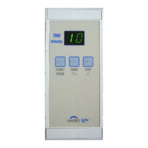
Inepro MicroTimer 2400 User manual

© 2019 Inepro B.V. All rights reserved
Technical Manual | MicroTimer 2400
MicroTimer 2400


Version 4.1.2 http://www.inepro.com
Table of Contents
.......................................................................................................1Introduction
...................................................................................................................................................................... 21 Design
.......................................................................................................................................................................... 2Extra functioning
...................................................................................................................................................................... 32 Versions
.......................................................................................................5Possebilities
...................................................................................................................................................................... 61 Basic functioning
.......................................................................................................7Settings
...................................................................................................................................................................... 81 Function Menu
...................................................................................................................................................................... 82 Function Overview
.......................................................................................................15Specifications
.......................................................................................................17Appendix


ATTENTION!!
Read this manual carefully before installing the MicroTimer 2400!
Mains connection
Guarentee
Security
Before connecting the appliance to the mains, check that the mains supply voltage corresponds to the voltage
printed on the type plate of the adapter. If the mains voltage is different, consult your supplier.
No guarantee can be given if safety regulations are not followed.
Always disconnect the power supply before handling anything inside the device.
This device is in conformity with the EMC directive and low-voltage directive.
CE Conformité Europeène (Conform European Norm)
WEEE Directive (Waste of Electrical and Electronic Equipment)
Inepro considers it important to properly take the climate into account. We therefore produce as many
climate-friendly products. Your new device contains materials which can be recycled and then reused. At the
end of life, specialized companies can dismantle the device, to materials which can be reused in order to
recycle and reuse. For example, the materials that must be discarded will be limited to a minimum. Please
take into account the rules and regulations in your area regarding the rules about disposal of packaging
materials, exhausted bateries and old equipment.
Thank you, Inepro BV
This device may only be used indoors.
Indoor User Only
Directives
Due to continuous product improvements this manual is subject to change without notice. This document
describes the technical and functional operation of the MicroTimer 2400. Greatest care has been taken drafting
the information in this manual and it may be said that it is reliable. However, the producer is not liable for any
shortcomings in the text or incompleteness of the information. Thank you for your decision to use the
MicroTimer 2400.
This document:


Introduction
Part
I

2 - MicroTimer 2400
Introduction
Introduction
The MicroTimer® standard control board design includes a minimum of functionality. The functionality of the MicroTimer®
can be expanded by means of additional “ECOS”® software modules. Thus, it is possible to produce perfectly customised
MicroTimers®. MicroTimer® outputs have two neutral relay points to control a connected device over a certain
programmable length of time. This MicroTimer® is programmed in a user-optimised way by means of three control keys.
With its potted electronics and its extensibility by means of “ECOS”® software modules the MicroTimer® is a very special
timer of its kind.
“ECOS”® : Electronic Customised Option System
Design
§
Very resistant plastic housing
§
Suitable for internal and external installation
§
Three keys: Start/Pause, Timer & Stop (internal and external)
§
Bright green 2-digit LED display
§
Extensibility by means of ECOS software modules
§
Supply voltage either 24 Volt or 240 Volt
Extra werking (with all ECOS modules)
The MicroTimer® can be activated with three freely programmable time-segments. The duration of these time-segments
can be set at 0 to 255 minutes.
Prior Time
The MicroTimer® starts with a prior time. During the prior time the length of the main time will be shown intermittently on
the display. During the prior time it is possible to reduce the main time if necessary. The prior time can also be bypassed so
that the main time will start automatically.
Time per periode (Main Time)
During the main time the remaining time will be shown on the display. When activating a pause a buzzer signal may be
generated. Another possibility consists of the automatic main time adjustment based on the progression of the service
counter.
Post Time
The main time is automatically followed by the post time. During the post time “Cl” (cool) is displayed. After the post
time it is possible to activate a clean function, in this case “CL” is displayed intermittently. This clean function inhibits
the MicroTimer®. Furthermore, there is an “after start” function by means of which an extra main time of 30 seconds can
be given at the end of the whole session.
Service Message
Registration facilities, as for example start, running time and service counters can also be used. The start and running time
counters may either be activated as counters, which can be reset, or as cumulative counter, which can not be reset.
Automatic representation of the Running time counter is affected by pressing the Stop key during 3 seconds. The service
counter generates a SR (service message) on the display

3
Versions
De versies
There is one type of MicroTimer®available as the functioning of the MicroTimer®mainly depends on the additional software
modules and the settings


Possebilities
Part
II

6 - MicroTimer 2400
Possebilities
Basic functioning (without ECOS modules)
In the basic version during stand-by a point (.) will be shown on the display.
As soon as the main time is connected the display will change into two hyphens (--).
Time per periode (Main Time)
The maximum period of time to be programmed in the MicroTimer® is 15 minutes. The main time starts after pressing the
timer-key, after inserting a coin or by means of a continuous external drive.
Output
The MicroTimer® output is programmable. It may be chosen between the standard “continue” output, which means that
both relays are activated during main time, and a “pulse” output, which means that a pulse is generated at the beginning
and the end of the main time.
Pause
The operator may choose either to allow the creation of a pause during the main time or not. If a pause is allowed, it can
be created by pressing the Start/Pause key. The operator can also choose between interrupting and continuing the main
time during the pause mode

Settings
Part
III

8 - MicroTimer 2400
Settings
Function Menu
The MicroTimer® can be programmed by means of three control keys, which are integrated in the front panel of the
machine. By activating these control keys, the function menu can be programmed, modified or read. The control keys are
marked on the outside by Start/Pause, Timer and Stop.
1 . Up 2 . Sta rt 3 .Down
ATTENTION!
If the dip switch 1 is in an “OFF” position, all settings can be carried out, and vice versa; if the dip switch is “ON”, than
the settings are disabled. (Dip switch 1 is the nearest to the buzzer).
1. Activation of the function menu:
2. Press the Start/Pause and Stop keys simultaneously when in “stand by”;
3. Release both control keys, F1 will be displayed;
4. Scroll to the desired function by means of the Start/Pause (Up) and Stop control keys (Down);
5. Press the Start/Pause and Stop keys simultaneously to read or modify the current value of the selected function;
6. Modify the value by pressing the Start/Pause key (Up) or the Stop key (Down) ;
7. Quit and confirm the set-value by pressing the Start/Pause key (Up) and the Stop key (Down) simultaneously. The
function menu is shown again and another function can be selected (go to step 3) or the menu can be closed (go to step
7);
8. Quit the function menu by scrolling to function F0 and pressing the Start/Pause key (Up) and the Stop key (Down)
simultaneously
Function overview
This is an overview of all the functions in the MicoTimer AD2400. Functions with the symbol need the relevant ECOS
module. These software modules need to be bought and installed with the unit.
Function F0, Quitting the function menu
Function
Quit Menu
A ctiv ate this function the MicoTimer® to program or quit the menu.
Function F1, Main time setting per coin
Function
Main time setting per coin
Value
Descr iption
Default
1-15
Main time duration in minutes, per 1 inserted coin. (1-15 minutes)
12 (M ax. 15)
1-255
With EC O S module EM-01 y ou can set the main time from 1-255
minutes.
12 (M ax. 255)
Note:
If a v alue of more than 100 minutes is programmed the indication will be display ed
intermittently in tw o parts; first display “1”, second display “00”.

9
Function Overview
Function F2, Prior time setting
(ECOS module EM-02)
Function
Pr ior time setting. Before the main time is started, r elay 2 will be closed. Pr ior
T ime is the dur ation in minutes that relay 2 is closed befor e the main time
begins. T he relay will remain closed dur ing the the main time.
Value
Descr iption
Default
1-255
Duration in minutes
3
Function F3, Post time setting
(ECOS module EM-03)
Function
Post time setting. When the main time has ended, relay 2 is still closed. Post
T ime is the dur ation in minutes that r elay 2 will stay closed after the main time
has ended. A fter this r elay 2 will open.
Value
Descr iption
Default
1-255
Duration in minutes
2
Function F4, Maximum amount of coins
(ECOS module EM-04)
Function
Maximum amount of coins. Maximum amount of coins that can be activated to
increase cumulatively the total main time.
Value
Descr iption
Default
1-255
Max. number of coins
1
Note:
The v alue of this setting has to be at least 1.
Function F5, Minimum amount of coins
(ECOS module EM-05)
Function
Minimum amount of coins which have to accepted in or der to activate the
MicoT imer ®. For example, 3 coins for 5 minutes. T he value of this setting has
to be at least 1. If the pr ogr ammed value is higher than 1 , the coins will be
shown on the displayed until the necessar y amount is r eached.
Value
Descr iption
Default
1-255
Max. number of coins
1
Note:
The v alue of this setting has to be at least 1.
Configuration example F4 & F5 , with F1 (time per coin) set at 5 minutes
Example #
Event
1
2
3
4
5
6
1 e coin inser ted
5 minutes
5 minutes
0 minutes
0 minutes
5 minutes
0 minutes
2 e coin inser ted
-
5 minutes
5 minutes
10 minutes
5 minutes
10 minutes
3 e coin inser ted
-
-
-
-
5 minutes
5 minutes
T otal time
5 minutes
5 minutes
10 minutes
10 minutes
15 minutes
15 minutes
Value F4 (M ax.
Coins)
1
1
2
2
3
3
Value F5 (M in. C oins)
1
2
1
2
1
2

10 - MicroTimer 2400
Settings
Function F6, Service indicator 1
(ECOS module EM-06)
Function
T he maximum amount of pr ogr ammable r unning hour s befor e a revision ser vice
is r equir ed. T his r egister will count down per 1 0 0 0 minutes of r elay 1 activity .
T he v alue of this r egister r epr esents the number x 1 0 0 0 minutes, e.g. 5 =
5 0 0 0 minutes.
When the counter reaches zero, the message will appear on the display.
T his is the standard message to indicate that a r evision “service” is required.
Value
Descr iption
Default
1-254
Number of serv ice minutes before serv ice on dev ice is required.
When this counter has counted dow n to zero (serv ice counter = 0) the
M icoT imer® w ill display . N umber of minutes = Setting x 1000
minutes.
0
255
Disabled
Note:
The timer will keep running as usual. To reset, simply set the v alue to a
v alue higher then '0'.
Function F7, Service indicator 2
(ECOS module EM-07)
Function
T he maximum amount of pr ogr ammable r unning hour s befor e a revision ser vice
is r equir ed. T his r egister will count down per 1 0 0 0 minutes of r elay 1 activity .
T he v alue of this r egister r epr esents the number x 1 0 0 0 minutes, e.g. 5 =
5 0 0 0 minutes.
When the counter reaches zero, the message will appear on the display.
T his is the standard message to indicate that a r evision “service” is required.
Value
Descr iption
Default
1-254
Number of serv ice minutes before serv ice on dev ice is required.
When this counter has counted dow n to zero (serv ice counter = 0) the
MicoTimer® w ill display and is inhibited until the counter is reset.
Number of minutes = S etting x 1000 minutes.
0
255
Disabled
Note:
To reset, simply set the v alue to a v alue higher then '0'.
Function F8, Buzzer setting
(ECOS module EM-08)
Function
Buzzer Setting
Setting
Descr iption
Default
Note:
This setting is not applicable in this dev ice.
0
Function F9, Clean Function
(ECOS module EM-09)
Function
By means of this function it is possible to for ce the cleaning of a connected
device. A fter the posted time the M icoT imer ® does not accept any fur ther coin
anymor e. T his blockage can be r aised by pr essing the inter nal or external up
key for 3 seconds. T o indicate the necessity of cleaning will appear
intermittently on the M icoT imer ® display.
Setting
Descr iption
Default
00
C lean function off
1
01
C lean function on.

11
Function Overview
Function FA, Standard or external start mode
Function
Start Mode T ype
Setting
Descr iption
Default
00
The M icoTimer can be started by pushing the Timer button or by generating
a puls, w hich is longer as 200 msec, on the external connection (remote
button print).
1
01
The MicoTimer can be started by generating a pulse betw een the 20 and 200
msec. This setting is dedicated for mechanical coin mechanisms.
Note:
In case the coin mechanism input is selected (setting “01”) then starting the
timer w ith the Timer button is not possible.
When the timer button is selected (setting “00”), then by generating a signal
on the coin mechanism input, the pre-time can be bridged to start the main-
time. (This can be done by short circuiting the coin mechanism connection
pins)
Function FB, Running time counter (reset possible)
(ECOS module EM-10)
Function
Running time counter (r eset possible)
Setting
Descr iption
Default
0-6
The running time counter is an electronic counter, w hich registers
cumulativ ely the number of minutes the main channel, relay 1, has been
operativ e. The main channel relay 1 is only activ e during the main time of
the MicoTimer®. It is possible to scroll the counters by pressing the up key .
The 6-digit counter is read back to front, as follow s;
C ounter index
Example V alue
1
1
2
3
3
7
4
5
5
0
6
0
In this example the total running time amounts to 005731 minutes
#
V alue
1
0
2
0
3
0
4
0
5
0
6
0
Note:
Resetting the counters
A fter reading the counters, these can be reset. The reset-procedure is as follow s;
1) A fter hav ing read the count (6X) press the up and the dow n key s simultaneously
a) (2 hy phens) w ill appear on the display
2) To reset the counter press the up key ,
a) w ill appear on the display
3) Now press the up and the dow n key s simultaneously
a) The counters are reset and the M icoTimer® w ill automatically resume its function.
Note: if necessary , y ou can also read out the indication on the counter w ithout resetting it during
the stand-by period, to do so, press the dow n key during 3 seconds. The indication of the
counters of F unction F B w ill be represented automatically , but cannot be reset.
Function FC, Coin counter (reset possible)
(ECOS module EM-10)
Function
Coin counter (r eset possible) T his counter r epr oduces the number of coins.
Setting
Descr iption
Default
0-6
Reading procedure as in function F B .
0
Note:
C ounter can be reset, procedure like in function F B .
Function FD, Running time counter (reset impossible)
(ECOS module EM-12)
Function
Running time counter (r eset impossible)
Setting
Descr iption
Default
0-6
Reading procedure as in function F B .
0
Note:
C ounter can't be reset, procedure like in function F B .
11
11
11
11
11

12 - MicroTimer 2400
Settings
Function FE, Coin counter (reset impossible)
(ECOS module EM-12)
Function
Coin counter (r eset possible) T his counter r epr oduces the number of coins.
Setting
Descr iption
Default
0-6
Reading procedure as in function F B .
0
Note:
C ounter can't be reset, procedure like in function F B .
Function FF, TAT (Automatic main time adjustment)
(ECOS module EM-11)
Function
T A T (A utomatic main time adjustment) A ctivating this function, the main time
is automatically adjusted on the basis of the ser vice counter progr ession (F6 &
F7 ). If one of the two ser vice counter s is pr ogr ammed again the T A T function
has to be r eset again as well.
Setting
Descr iption
Default
00
TA T function disabled
1
01
TA T function enabled
note:
Running hour s
Pr olongation per
minute
Running hour s
Pr olongation per
minute
0 – 49
+ 0 sec p/m
450 – 499
+ 24 sec p/m
50 – 99
+ 3 sec p/m
500 – 549
+ 27 sec p/m
100 – 149
+ 5 sec p/m
550 – 599
+ 30 sec p/m
150 – 199
+ 8 sec p/m
600 – 649
+ 30 sec p/m
200 – 249
+ 11 sec p/m
650 – 699
+ 30 sec p/m
250 – 299
+ 14 sec p/m
700 – 749
+ 30 sec p/m
300 – 349
+ 16 sec p/m
750 – 799
+ 30 sec p/m
350 – 399
+ 19 sec p/m
800 – 849
+ 30 sec p/m
400 – 449
+ 22 sec p/m
850 - 899
+ 30 sec p/m
The time adjustment is preprogrammed and depend on the maximum number of running hours
set in F 6 & F 7 . This table show s the prolongation per range of running hours.
Function P0, Output configuration
Function
Output configur ation. Relay output type.
Setting
Descr iption
Default
00
Signal output, w hich is activ e throughout the w hole session.
0
01
Pulse output, w hich is briefly activ e/generating a pulse in the beginning of the
main time and in the beginning of the post time.
note:
This diagram
show s the
response of the
relay s at the signal
and pulse setting.
Function P1, External drive facility
Function
External drive facility
Setting
Descr iption
Default
00
Starting the M icoTimer happens through a short pulse on the timer button or
coin input (Depending on menu F A )
0
01
Starting the MicoTimer happens by an external dev ice. This dev ice controls
the main time. In case the signal is activ e, then also the timer is activ e,
unless the set time has ended. Interrupting the activ e signal w ill put the
MicoTimer in post-time (w hen enabled). The controls is depending on the
setting in menu F A (remote button print input or coin mechanism input).
note:
This setting must be set on 0 for this dev ice.
11
11
10 10
11
11

13
Function Overview
Function P2, After start
(ECOS module EM-07)
Function
A fter star t; A t the end of a whole session it is possible to allow one extr a time
of 3 0 seconds. T o obtain this time the down key has to be pressed. T his setting
provides a solution for machines, which have to be connected for a shor t period
of time after the pr ogr ammed time has expir ed, e.g. to open the electr ic door of
a washing machine.
Setting
Descr iption
Default
00
A fter start is disabled
1
01
A fter start is enabled
Function P3, Display indication
(ECOS module EM-14)
Function
Display indication, choice between of .
Setting
Descr iption
Default
00
Display during stand by one point ( ), during the prior time, main time
and post time tw o hy phens w ill be display ed ( ).
1
01
Display indication in minutes
Function P4, Reduction of the main time
(ECOS module EM-13)
Function
Reduction of the main time
Setting
Descr iption
Default
00
Main Time reduction disabled
1
01
Main Time reduction enabled
Note:
See P 7 for configuration.
Function P5, Pause during the main time
Function
Pause dur ing the main time
Setting
Descr iption
Default
00
Pause during the main time disabled
1
01
Pause during the main time enabled
note:
During a pause situation the remaining time w ill be intermittently indicated (if display indication is
set to 1 (P3 )). N ote; this function w orks only w ith long distance board!
Function P6, Main time during the pause
Function
Main time dur ing the pause
Setting
Descr iption
Default
00
Main time stops during the pause
1
01
Main time continues during the pause
Function P7, Main time reduction configuration
Function
Main time r eduction dur ing the main time
Setting
Descr iption
Default
00
The main time w ill be finished immediately w hen the dow n key is pressed.
0
01
It is possible to shorten the main time during the main time or prior time (by
means of the dow n key ). When the main time is shortened it w ill alw ay s
start w ith w hole minutes.
note: When activ ating this function, function P4 has to be enabled as
w ell (ev en if the prior-time is not used).
02
The dow n key w ill be blocked during the main time. S o during the prior-time
the main time can be reduced beforehand, as long as P4 is enabled.
O therw ise main time can not be reduced.
13
13
13
13

14 - MicroTimer 2400
Settings
Function P8, Payment during main time
Function
Payment dur ing main time
Setting
Descr iption
Default
00
Pay ment during main time is disabled
0
01
Pay ment during main time is enabled
note:
The maximum amount of coin pulses can be programmed in function F 4 .
9
Table of contents
Other Inepro Timer manuals
Popular Timer manuals by other brands

CAPITAL SPORTS
CAPITAL SPORTS 10028194 manual

Orbis
Orbis ASTRO NOVA CITY user manual
ELEKTROBOCK
ELEKTROBOCK CS3C-1B quick start guide
Theben
Theben SIMPLEXA 601 Installation and operating instructions

CAPITAL SPORTS
CAPITAL SPORTS CS Timer 6 manual
DARKROOM AUTOMATION
DARKROOM AUTOMATION f-STOP TIMERS quick guide
