Inficon Sensistor ILS500 F User manual
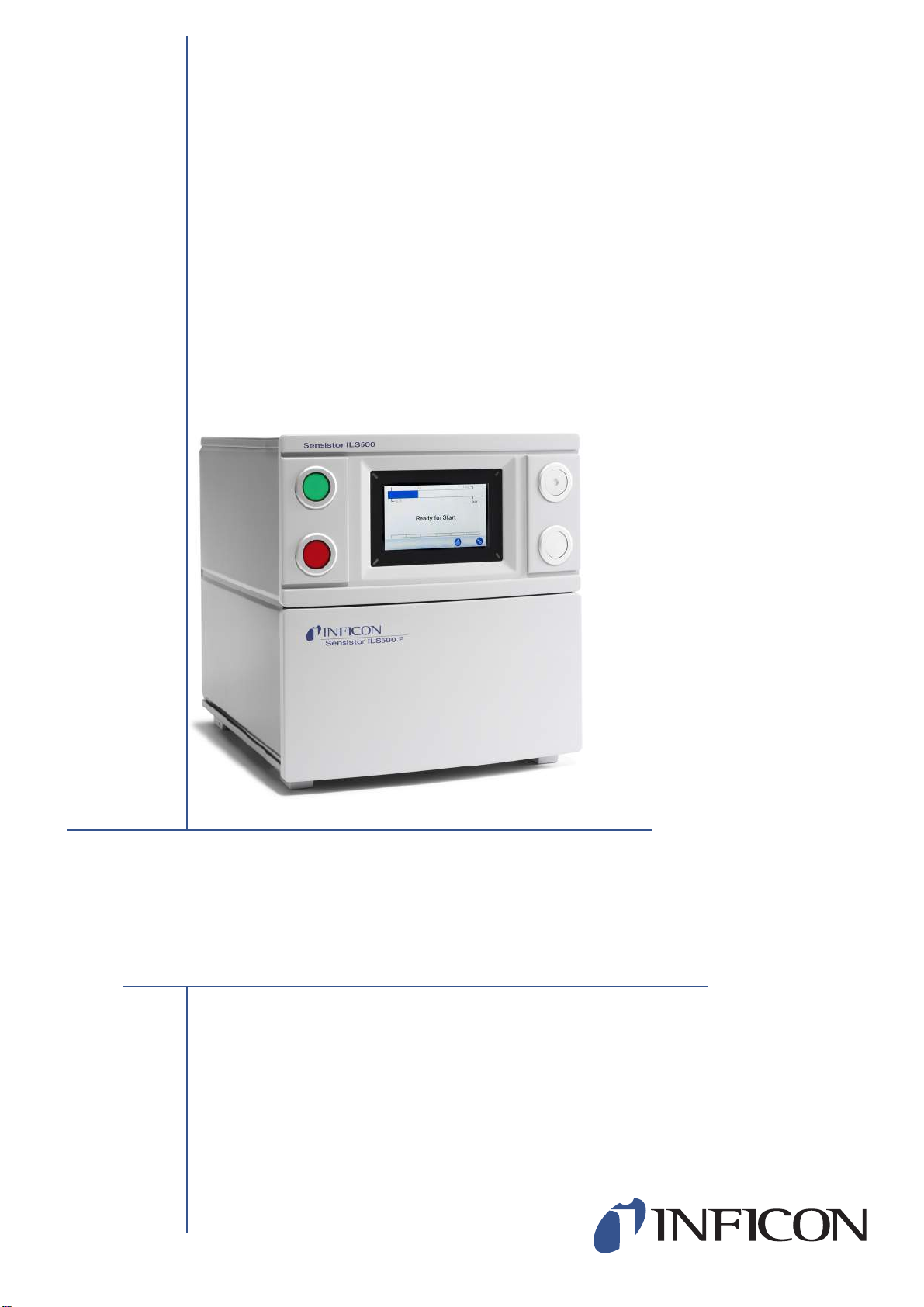
Sensistor ILS500 F
O P E R A T I N G M A N U A L
ninp69e1-a (1410)
Leak Detection Filler
Type no. ILS.210.306


Content 3
ninp69e1-a (1410)
Content
1 General Information 8
1.1 About This Manual 8
1.2 Introduction to the ILS500 F 8
1.3 Disposal 9
2 Equipment and Storage 10
2.1 Supplied Equipment 10
2.2 Required Equipment 11
2.3 Storage 11
3 ILS500 F Description 12
3.1 Front View 12
3.2 Rear View (Electrical) 13
3.3 Configuring Ports and Interfaces (Electrical) 14
3.4 Rear View (Pneumatical) 15
3.5 Configuring Ports and Interfaces (Pneumatical) 16
3.6 Labels 16
4 Setup 18
4.1 Placement of the ILS500 F 18
4.2 Electrical Connections 19
4.3 Pneumatic Connections 21
4.4 Connect External Leak Detector 25
4.5 Set Up Test Area 25
5 Menu System 27
5.1 ILS500 F Display 27
5.2 Passwords 29
5.3 Menu Overview 30
6 Using the ILS500 F 35
6.1 Test Sequence 35
6.2 Run a Test 36
7 Recipes 38
7.1 Recipe Overview 38
7.2 Create a Recipe 39
7.3 Test Settings 40
7.4 Optimizing the Test Cycle 46
8 Troubleshooting 50
8.1 Fault Symptoms 50
8.2 Perform Hardware Test 50
9 Maintenance Instructions 62
9.1 Maintenance Plan 62

Content 4
ninp69e1-a (1410)
9.2 Maintenance 63
9.3 Functional Verification 69
10 Service 70
11 Technical Data 71
11.1 Electrical Specifications 71
11.2 Pneumatic Specifications 72
11.3 Other Data 73
11.4 Interfaces and Connectors 74
12 Spare Parts and Accessories 84
13 Support from INFICON 85
13.1 How to Contact INFICON 85
13.2 Returning Components to INFICON 85
14 Declaration of Conformity 86
15 Declaration by the Manufacturer 87
Appendix
A: Parameter Index 88
5
ninp69e1-a (1410)
General Safety Precautions
Definitions of Warning, Caution and Notice
General Safety
Failure to observe the following precautions could result in serious personal
injury:
Warning
Indicates procedures that must be strictly observed to prevent hazards to persons.
Caution
Indicates procedures that must strictly be observed to prevent damage to or destruction
of the instrument
.
Notice Indicates special requirements the user must comply with.
Warning
Tracer Gases can be flammable or asphyxiating. Use only ready-made Tracer Gas
mixtures.
Warning
Since the tracer gas mix contains no oxygen, releasing large amounts of the gas in a
confined space may lead to asphyxiation.
Warning
Compressed gases contain a great deal of stored energy. Always carefully secure
gas bottles before connecting a pressure regulator. Never transport gas bottles with
a pressure regulator fitted.
6
ninp69e1-a (1410)
Failure to observe the following precautions could result in damage to the
equipment:
Warning
Pressurizing objects at too high pressures can lead to the object bursting. This in
turn can result in serious injury or even death. Never pressurize objects that have
not previously been burst-tested or have otherwise been approved for the test
pressure you intend to use.
Caution
If the tracer gas filler suffers external damage, it must be checked and repaired by a
service organization authorized by INFICON.
Caution
Always switch power off before connecting or disconnecting any cable.
Notice Before connecting the tracer gas, confirm that the connectors or test
object is designed for operating at the test pressure to be used.
7
ninp69e1-a (1410)
Safety ILS500 F
INFICON can not take any responsibility for the consequences arising from
inappropriate use of certain test pressures.
Warning
The ILS500 F must never be introduced to pressures higher than that approved for
the object to be tested and never beyond the ILS500 F specification.
Warning
Be sure to have a pressure relief valve in case of accidental tracer gas pressure
increase.
Warning
When dealing with high pressures, a blast protection is needed between the Test
Ports and the Test Object.
Warning
When dealing with test objects that cannot stand high pressure increase, make sure
to mount a flow control valve on the Test Ports.
Warning
Make sure not to confound Compressed Air and Tracer Gas.
Notice The ILS500 F has no internal emergency stop circuit. ILS500 F is
prepared for integration into an external emergency stop circuit.
Check that all relevant legislation and safety standards are complied with
before putting the ILS500 F into service. See further information under
Installation.

General Information 8
ninp69e1-a (1410)
1 General Information
Please read this Operating Manual carefully before putting your Sensistor ILS500 F
into service. When reading, please pay particular attention to the WARNINGS,
CAUTIONS and NOTICES found throughout the text.
1.1 About This Manual
The purpose of this manual is to:
•Describe the working principles of the ILS500 F and its different parts
•Show examples of different types of test stations
•Teach the reader how to set up the ILS500 F for different test purposes
1.1.1 Document History
1.2 Introduction to the ILS500 F
The Sensistor ILS500 F is a stand alone tracer gas filler with all necessary functions
integrated in one very compact housing.The purpose of the ILS500 F is to make it
possible to set up a fully automatic leak test system quickly, to a low cost.
The ILS500 F can also be combined with both hydrogen and helium INFICON leak
detectors.
If a ISH2000 Hydrogen Leak Detector is connected to the ILS500 F, via the Probe
Control Port and Leak Detector Port, the ILS500 F has the same functionality as
ILS500. For information on how to setup this configuration, please contact INFICON.
1.2.1 Intended Use
ILS500 F is designed for indoor use only.
All functions are accessible and programmable using a touch panel, a PC or via the
Internet. The test sequence is controlled by an integrated controller.
Revision Date Remark
a 10-2014 First edition
Notice ILS500 F is not compatible with AP29, AP55, and AP57.

9General Information
ninp69e1-a (1410)
1.2.2 Available Configurations
Sensistor ILS500 F
The actual configuration is shown on the ILS500 F display during start-up and in the
menu when clicking Setup >> Info.
1.3 Disposal
Sensistor ILS500 F
Standard For common tracer gas leak detection
High Pressure (HP) When a higher tracer gas pressure is needed.
According to EU legislation, this product must be recovered for
separation of materials and may not be disposed of as unsorted
municipal waste.
If you wish you can return this INFICON product to the manufacturer
for recovery.
The manufacturer has the right to refuse taking back products that
are inadequately packed and thereby presents safety and/or health
risks to the staff.
The manufacturer will not reimburse you for the shipping cost.
Shipping address:
INFICON AB
Westmansgatan 49
582 16 Linköping
Sweden
Equipment and Storage 10
ninp69e1-a (1410)
2 Equipment and Storage
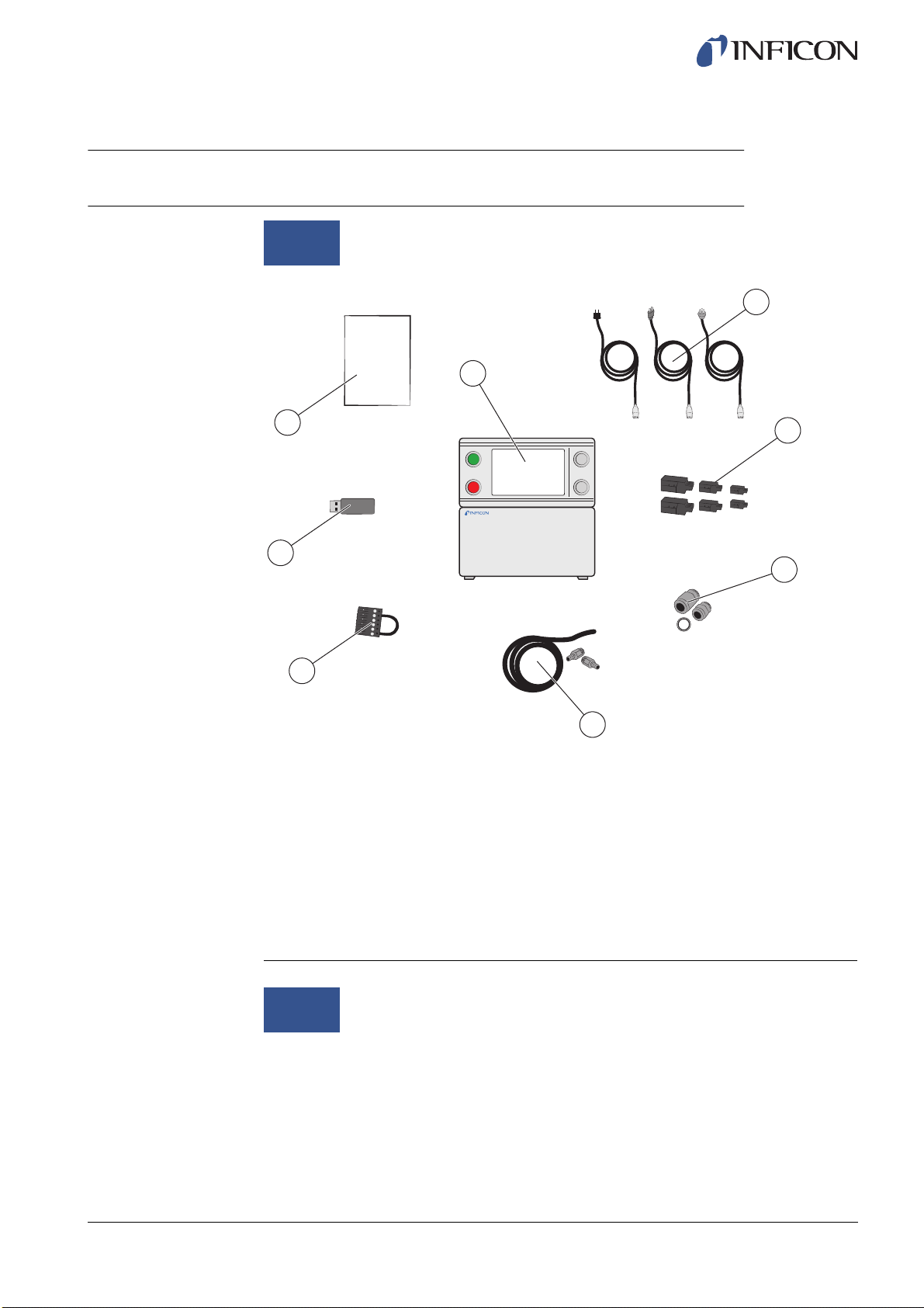
2.1 Supplied Equipment
Supplied Equipment
Accessories to the ILS500 F can be found on page 84.
Notice When receiving the equipment, check that it has not been damaged
during transport.
1 ILS500 F
2 Power Cables (EU, UK, US)
3 Screw Terminal Connectors for External I/O Signals
4 Thread Converter Set (ISO to NPT Conversion)
5 Hose Connection Kit
6 Safety Override Loopback
7 USB flash drive with relevant manuals
8 Operating Manual Sensistor ILS500 F (this manual)
2
8
7
6
1
3
4
5
ILS500 F
OM
Notice Some pneumatic ports are plugged upon delivery. Store the removed
plugs. They are used for future hardware testing.

11 Equipment and Storage
ninp69e1-a (1410)
2.2 Required Equipment
Required Equipment
2.3 Storage
For prolonged storage, factors such as temperature, humidity, saline atmosphere etc.,
may damage the detector elements.
Please contact your local representative for more information.
1 Tracer Gas
2 Compressed Air
3 Two-Step Gas Regulator
4 Compressed Air Filter
5 Exhaust Hose
6 Emergency Stop Circuit (recommended)
13
24
5 6
ILS500 F Description 12
ninp69e1-a (1410)
3 ILS500 F Description
ILS500 F is manually controlled using the START and STOP buttons and the menu
system of the touch panel. The screen also shows the steps of the test sequence
graphically and in plain text.
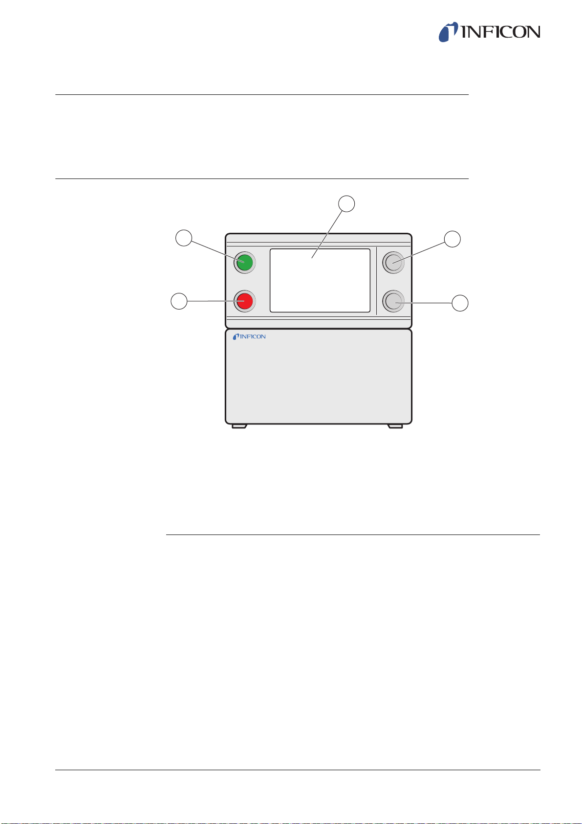
3.1 Front View
ILS500 F Front View
1 Red lamp
2 Green lamp
3 ILS500 F Touch panel
4 START button
5 STOP button
1
2
3
4
5

13 ILS500 F Description
ninp69e1-a (1410)
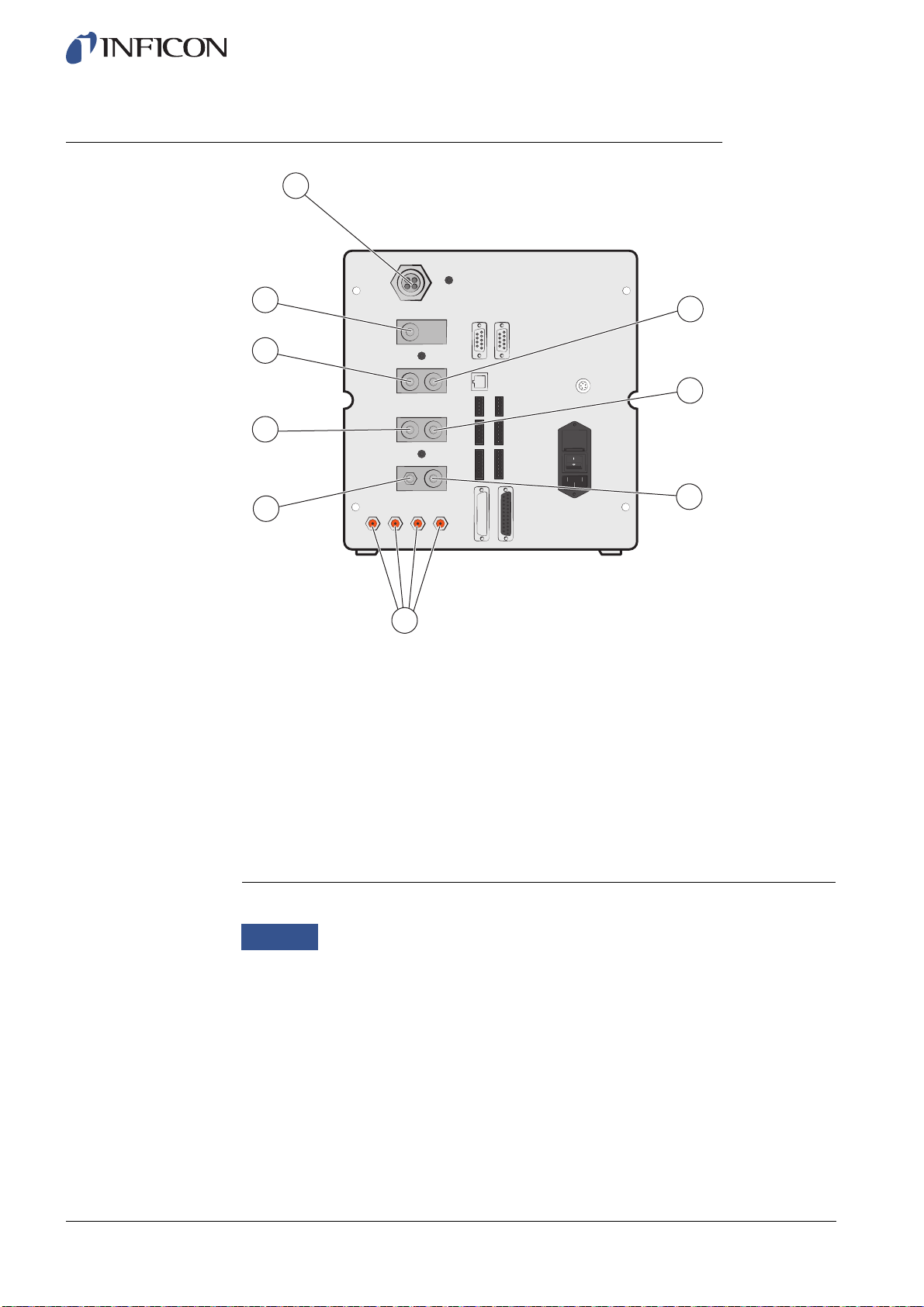
3.2 Rear View (Electrical)
Rear View (Electrical)
For more information, see on page 71.
1 Leak Detector (for connection of ISH2000 or T-Guard)
2 Safety Interface
3 Fuses
4 Power Switch
5 Power Input
6 Probe Control Port (for connection of ISH2000)
7 Control Output
8 Tooling Interface
9 Status Output
10 Inputs 1 and 2 (optional)
11 Ethernet
12 Printer Port/RS232
12 1
11
7
8
9
10
5
2
3
4
6

ILS500 F Description 14
ninp69e1-a (1410)
3.3 Configuring Ports and Interfaces (Electrical)
Port/Interface Connect
Leak Detector ISH2000 or T-Guard.
Safety Interface Emergency Stop Circuit.
Power Input Power Cable.
Probe Control Port Pin-to-pin cable
(for external mounting of ISH2000 Leak Detector).
Control Output Optional External Valves.
Tooling Interface External sensors for tooling control.
Status Output Light Tower etc.
Input 1 (optional) Analogue Input
(not supported by std software).
Digital Input
(not supported by std software).
Input 2 Active Holder for Hand Probe
(if ISH2000 Leak Detector is connected).
Ethernet Ethernet
(remote view and control of touch panel).
Printer Port/RS232 Serial Printer.
Logging Device
(e.g. PC).
Remote Control
(START, STOP etc.).
15 ILS500 F Description
ninp69e1-a (1410)
3.4 Rear View (Pneumatical)
Rear View (Pneumatical)
1 Optional Port
2 Test Port 2
3 Compressed Air Input
4 Tooling Valve Outputs 1-4
5 Vacuum Gauge Vent
6 Test Port 1
7 Tracer Gas Input
8 Plugged Port
9 Exhaust
1
5
6
9
8
7
4
3
2
Notice Do not remove the plug from the plugged port in pos. 8.

ILS500 F Description 16
ninp69e1-a (1410)
3.5 Configuring Ports and Interfaces (Pneumatical)
3.6 Labels
Device Label
Tooling Label
Port/Interface Port Thread
Exhaust Barb Fitting:
ID 25 mm (1 in.)
Tracer Gas Input
Test Port 1
Test Port 2
Compressed Air Input
BSP 3/8" (NPT 3/8" adaptor included)
BSP 3/8" (NPT 3/8" adaptor included)
BSP 3/8" (NPT 3/8" adaptor included)
BSP 3/8" (NPT 3/8" adaptor included)
Tooling Valve Outputs 1-4 Hose Connectors:
OD 4 mm (0.16 in.)

17 ILS500 F Description
ninp69e1-a (1410)
Pneumatical Label Electrical Label
Setup 18
ninp69e1-a (1410)
4 Setup
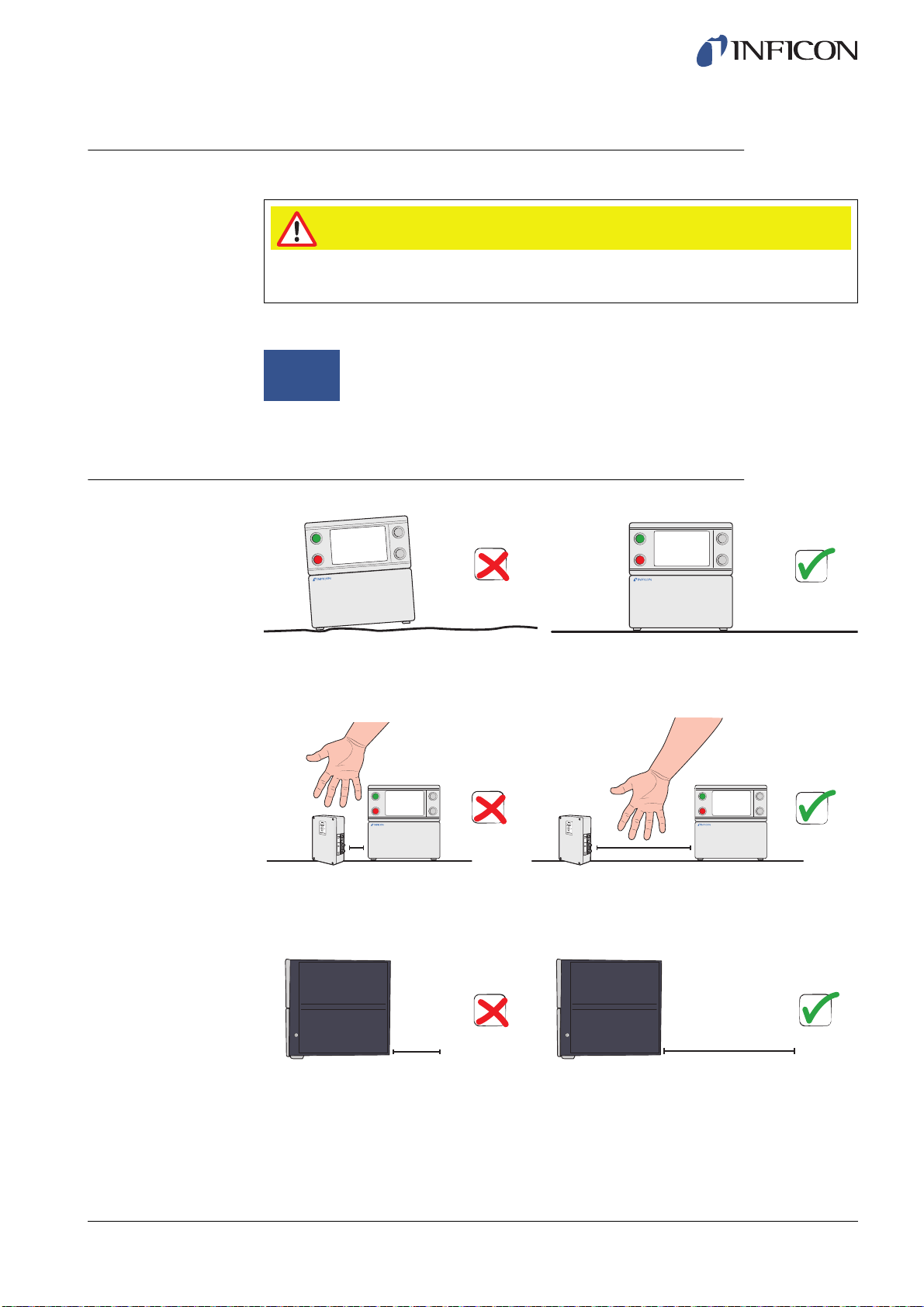
4.1 Placement of the ILS500 F
Place the ILS500 F on a flat surface, as close as possible to the test fixture and
ventilation system.
Some free space must be provided around the ILS500 F to enable maintenance and
service access.
Ensure that there is at least 350 mm (14 in.) of free space behind the ILS500 F to
enable removal of service hatches, connection of supplies, test fixture etc.
Caution
Check that you comply with all relevant legislation and safety standards before
putting your ILS500 F into service.
Notice Start-up time for the leak detectors can be up to 10 minutes, depending
on the condition.
≥350 mm (14 in.)
19 Setup
ninp69e1-a (1410)
4.2 Electrical Connections
4.2.1 Setting Up an Emergency Stop
You have the following two options to prepare the ILS500 F for start:
•Connect the ILS500 F through an external emergency stop relay.
•Short circuit the SAFE SPLY terminal to “+24 V” on the Safety Connector.
Use the Safety Override Loopback delivered with the unit.
Notice The front feet under the ILS500 F can be flipped out to raise the front for a
better viewing angle.
Caution
To short-circuit is not recommended and should only be made for preliminary testing
before connecting compressed gases or test tooling with moving parts.
Notice ILS500 F will not start testing unless an emergency circuit has been
installed. This is ordered separately. For more information, see on page
84.
Setup 20
ninp69e1-a (1410)
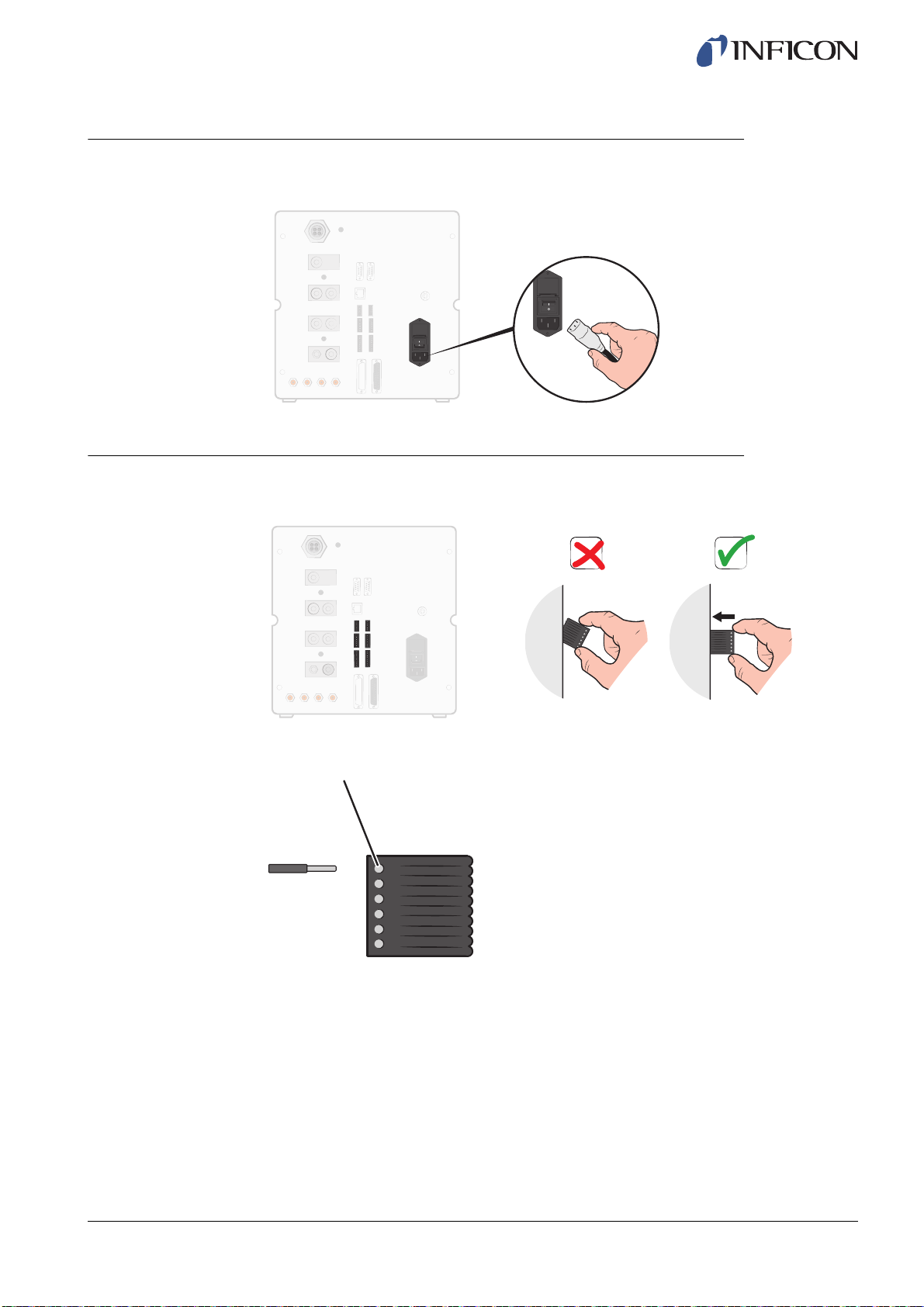
4.2.2 Connecting to Mains
1Plug the Power Cable into the Power Inlet of the ILS500 F and into the nearest
socket.
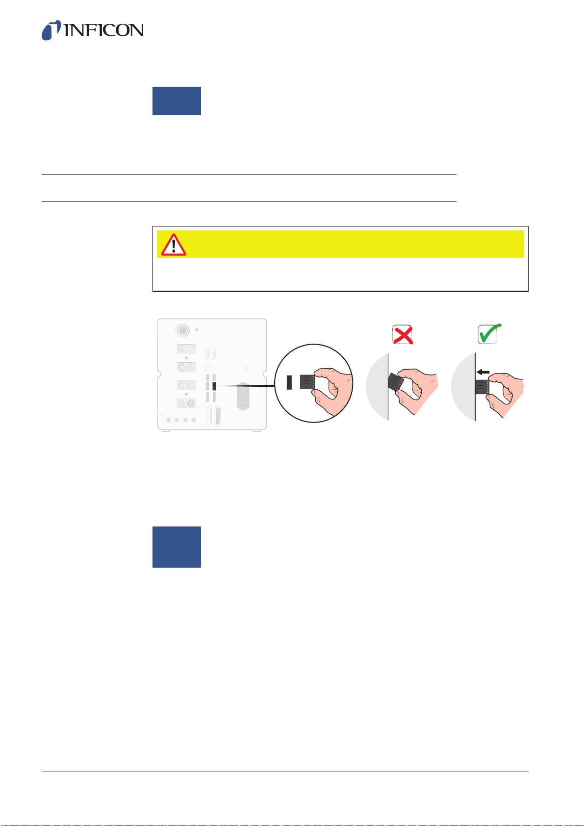
4.2.3 Connecting Extra Features
When using the ports for Options, Status, Tooling and Control, make sure to mount the
connectors as shown below.
For more information about the connection ports, see on page 71.
Top pin is number 1
Other manuals for Sensistor ILS500 F
1
Table of contents


