Voith ARGO HYTOS Ecoline UMPC2 045 User manual

Subject to change · Filter and recirculating pump unit UMPC2 045 · 0322 · EN
Page 1
www.argo-hytos.com
Read safety and operating instructions before use.
Note: The indicated data only serve to describe the product.
Specifications regarding the use of this product are only examples and suggestions.
Catalog specifications are no guaranteed features.
The information given does not release the user from his / her own assessments and inspection.
Our products are subject to natural wear and aging process.
© All rights are reserved by ARGO-HYTOS Polska, even in the event of industrial property rights.
Any right of disposal such as copying and distribution rights shall remain with us.
The picture on the title page shows a configuration example.
The delivered product may thus differ from the illustration.
Oil Service Unit
Ecoline UMPC2 045
Manual
Safety and operating instructions

Subject to change · Filter and recirculating pump unit UMPC2 045 · 0322 · EN
Page 2 www.argo-hytos.com
Content
Filter and Recirculating Pump Unit UMPC 045
Content.......................................................................................................................................................................... 2
1. About this documentation........................................................................................................................................... 4
1.1 Applicability of this documentation ................................................................................................................................. 4
1.2 Required and supplementary documentation .................................................................................................................. 4
1.3 Presentation of information ............................................................................................................................................ 4
1.3.1 Safety instructions .......................................................................................................................................................... 4
1.3.2 Symbols .......................................................................................................................................................................... 5
1.3.3 Terms ............................................................................................................................................................................. 5
1.3.4 Abbreviations .................................................................................................................................................................. 5
2. Safety instructions........................................................................................................................................................ 6
2.1 About this chapter .......................................................................................................................................................... 6
2.2 Intended use .................................................................................................................................................................. 6
2.3 Improper use .................................................................................................................................................................. 6
2.4 Reasonable foreseeable misuse ....................................................................................................................................... 6
2.5 Qualification of personnel ............................................................................................................................................... 6
2.6 General safety instructions .............................................................................................................................................. 7
2.7 Product and technology related safety instructions .......................................................................................................... 7
3. General instructions ..................................................................................................................................................... 8
4. Scope of delivery.......................................................................................................................................................... 9
5. About this product ..................................................................................................................................................... 10
5.1 Component overview ................................................................................................................................................... 10
5.2 Identification of the product .......................................................................................................................................... 12
6. Transport and storage................................................................................................................................................ 13
6.1 Transport ...................................................................................................................................................................... 13
6.2 Storage ......................................................................................................................................................................... 13
7. Assembly..................................................................................................................................................................... 14
8. Commissioning ........................................................................................................................................................... 15
8.1 After switching on ........................................................................................................................................................ 15
8.2 In case of power failure ................................................................................................................................................ 15
8.3 Venting ......................................................................................................................................................................... 15
9. Menu structure and functions................................................................................................................................... 16
9.1 Pump ON/OFF ............................................................................................................................................................... 17
9.2 Actual time ................................................................................................................................................................... 17
9.3 Profile management ...................................................................................................................................................... 17
9.4 Flow functions .............................................................................................................................................................. 18
9.4.1 Flow regulation ............................................................................................................................................................ 18
9.4.2 Auto flow (AF) function................................................................................................................................................. 19
9.4.3 Dosing function............................................................................................................................................................. 20
9.5 Temperature and relative humidity results ..................................................................................................................... 20
9.6 Cleanliness class functions............................................................................................................................................. 21
9.6.1 Cleanliness standard...................................................................................................................................................... 21
9.6.2 Auto switch-off (AS) function ....................................................................................................................................... 21
9.6.3 Alarms .......................................................................................................................................................................... 22
9.6.4 Charts ........................................................................................................................................................................... 23
9.7 Measurement data ........................................................................................................................................................ 23
9.7.1 General data memory ................................................................................................................................................... 23
9.7.2 Quick report memory .................................................................................................................................................... 24
9.8 Printing of results .......................................................................................................................................................... 24
9.9 Quick reports................................................................................................................................................................. 25
9.10 Dosing function ............................................................................................................................................................ 25
9.11 System setting............................................................................................................................................................... 25
9.11.1 Print and report settings ............................................................................................................................................... 25
9.11.2 Measurement options.................................................................................................................................................... 26

Subject to change · Filter and recirculating pump unit UMPC2 045 · 0322 · EN
Page 3
www.argo-hytos.com
9.11.3 Errors history ................................................................................................................................................................ 26
9.11.4 Info ............................................................................................................................................................................... 26
9.12 Filter element status ..................................................................................................................................................... 27
9.13 Error indication.............................................................................................................................................................. 27
10. Operation.................................................................................................................................................................... 28
10.1 Filtering of hydraulic fluids when refilling ...................................................................................................................... 29
10.2 Filtering of liquids in the bypass flow ............................................................................................................................ 30
10.3 Pumping of hydraulic fluids (e.g. waste oil, filter is bypassed) ........................................................................................ 31
10.4 Monitoring the oil cleanliness when filling machines and systems ................................................................................. 32
10.5 Monitoring the oil cleanliness when cleaning machines and systems in the bypass flow ................................................ 33
11. Repair and maintenance ............................................................................................................................................ 34
11.1 Maintenance overview .................................................................................................................................................. 34
11.2 Changing the filter element .......................................................................................................................................... 34
11.3 Removing the filter element .......................................................................................................................................... 35
11.3.1 Removing the filter element from the cover .................................................................................................................. 35
11.3.2 Attaching the filter element .......................................................................................................................................... 35
11.3.3 Installing the filter element ........................................................................................................................................... 36
11.4 Checking / changing the suction filter element (pump protection filter) ........................................................................ 36
11.4.1 Removing the suction filter ........................................................................................................................................... 36
11.4.2 Installing the suction filter ............................................................................................................................................. 36
11.5 Checking / cleaning OPCom protective filters ................................................................................................................ 37
12. Decommissioning ....................................................................................................................................................... 38
13. Disassembly ................................................................................................................................................................ 39
14. Disposal....................................................................................................................................................................... 40
14.1 Environmental protection .............................................................................................................................................. 40
15. Extension and conversion.......................................................................................................................................... 41
16. Troubleshooting.......................................................................................................................................................... 42
16.1 Basic procedure ............................................................................................................................................................. 42
17. Technical specifications .............................................................................................................................................. 44
17.1 Drawing ....................................................................................................................................................................... 44
17.2 Technical data ............................................................................................................................................................... 45
17.3 Operating conditions .................................................................................................................................................... 46
17.4 Hydraulic circuit diagram ............................................................................................................................................... 46
18. Appendix..................................................................................................................................................................... 47
18.1 Declaration of conformity ............................................................................................................................................. 47
18.2 Spare parts .................................................................................................................................................................... 48

Subject to change · Filter and recirculating pump unit UMPC2 045 · 0322 · EN
Page 4 www.argo-hytos.com
Title Document number Document type
Data sheet UMCP2_2203
1. About this documentation
1.1 Applicability of the documentation
This documentation is applicable for the following product:
›Oil Service Unit UMPC2 045
This documentation is written for technicians, operators, service engineers and system operators.
This document contains important information for safe and appropriate assembly, transport, activation, operation, usage, servicing,
dismantling and simple troubleshooting.
›Read this document completely and in particular Chapter 2, “Safety Instructions”, before you work with the product.
1.2 Required and supplementary documentation
Do not commission the product until you have received the documentation marked with the book icon and before you have under-
stood and complied with the information therein.
Table 1: Required and supplementary documentation
1.3 Presentation of information
So that this document can help you to work quickly and safely with your product, we use standardized safety instructions, symbols,
terms and abbreviations. For better understanding, these are explained in the following sections.
1.3.1 Safety instructions
In this documentation, safety instructions are faced with a sequence of actions which would result in the danger of personal injury
or damage to equipment. The measures described to avoid theses hazards must be observed.
Safety instructions are as follows:
›Warning signal: draws attention to the danger
›Signal word: indicates the severity of the danger
›Type and source of danger: specifies the type and source of the danger
›Consequences: describes the consequences in the event of non-compliance
›Action: indicates how the danger can be avoided
SIGNAL WORD
Type and source of danger
›Consequences of the danger
›Escaping or averting the danger
›Rescue (optional)
Table 2: Hazard classes according to ANSI Z536.6-2006
Warning sign, signal word Meaning
DANGER Indicates a dangerous situation which results in death or serious injury if not avoided.
WARNING Indicates a dangerous situation which may result in death or serious bodily injury if not avoided.
CAUTION Indicates a dangerous situation which may result in light to moderate injury if not avoided.
NOTE Indicates property damage: The product or surrounding could be damaged.

Subject to change · Filter and recirculating pump unit UMPC2 045 · 0322 · EN
Page 5
www.argo-hytos.com
1.3.3 Terms
In this documentation the following terms are used:
Table 4: Terms
1.3.4 Abbreviations
In this documentation the following abbreviations are used:
Table 5: Abbreviations
Term Meaning
Term Meaning
UMPC Pumping unit with condition monitoring
1.3.2 Symbols
The following symbols indicate notes which are not safety-relevant but increase the intelligibility of the documentation.
Table 3: Meaning of symbols
Symbols Meaning
If this information is not observed, the product cannot optimally be used or operated.
>Singular, independent action step / instruction
1.
2.
3.
Numbered instruction
The numbers indicate that the action steps follow one another.
This symbol indicates danger to equipment, material and environment.
This symbol indicates the risk of personal injury (minor injury).
This symbol indicates the risk of personal injury (death, serious bodily injury).
This symbol specifies that protective gloves should be worn.
This symbol specifies that safety shoes should be worn.
This symbol specifies that protective goggles should be worn.
This symbol specifies that the unit should be disconnected from the power supply.

Subject to change · Filter and recirculating pump unit UMPC2 045 · 0322 · EN
Page 6 www.argo-hytos.com
2. Safety instructions
2.1 About this chapter
This product was manufactured according to the generally recognized standards of engineering. Nevertheless, there is a danger of
injury or damage if you do not observe this chapter and the safety instructions in this documentation.
›Read this document thoroughly and completely before working with the product.
›Retain this document and ensure that it is available for all users at all times.
›Always include the necessary documentation when passing the equipment along to a third party.
2.2 Intended use
This product is a hydraulic component.
You may use the product for the following:
›for filtration of hydraulic fluids in the bypass flow on machines and systems, taking account of the technical data.
›for filtration of hydraulic fluids during filling of machines and plants, taking into account the technical data
›for pumping of hydraulic fluids (e.g. waste oil, filter element is bypassed), taking into account the technical data
›for monitoring the oil cleanliness in the bypass flow during cleaning or filling of machines and plants
This product is intended for professional use only and not for private use.
"Intended use" also includes that you have completely read and understood this documentation, in particular Chapter 2
"Safety Instructions".
2.3 Improper use
Any other use than the intended use described, is improper and inadmissible.
If unsuitable products are installed or used in safety-related applications, unintended operating states may occur in the application,
which may cause personal injury and / or property damage.
Therefore only use this product in safety-related applications if this use is explicitly specified and permitted in the product documentation,
e.g. in explosion protection areas or in safety-related parts of a control system (functional safety).
ARGO-HYTOS Polska assumes no liability for damages resulting from improper use. The risks associated with improper use are solely
with the user.
2.4 Reasonable forseeable misuse
The delivery of the following media is forbidden:
›others than listed in Chapter 18.1 "Technical data"
especially:
›flammable liquids such as petrol or thinner (explosion hazard)
›foodstuffs
›sludge and sediment
The operator alone is liable for damages resulting from improper use.
2.5 Qualification of personnel
The operations described in this document require fundamental knowledge of mechanics and hydraulics as well as knowledge of the
appropriate technical terms. In order to ensure safe use, these operations may therefore only be carried out by a correspondingly
skilled worker or an instructed person under the guidance of a skilled worker.
A skilled worker is someone who can - based on his / her technical education, knowledge and experience as well as knowledge of
the respective regulations of the jobs assigned to him / her - recognize possible dangers and ensure appropriate safety measures.
A skilled worker must observe the relevant technical regulations.

Subject to change · Filter and recirculating pump unit UMPC2 045 · 0322 · EN
Page 7
www.argo-hytos.com
2.6 General safety instructions
›Observe the valid regulations for accident prevention and environmental protection.
›Observe the safety regulations and requirements of the country in which the product is used / applied.
›Only use ARGO-HYTOS products that are in technically perfect condition.
›Observe all instructions on the product.
›People who assemble, operate, disassemble or maintain ARGO-HYTOS products may not do so under the influence of alcohol,
other drugs or medications that affect the responsiveness.
›Only use manufacturer-approved accessories and spare parts, in order to prevent personal danger due to unsuitable
spare parts.
›Observe the technical data and ambient specifications specified in the product documentation.
›If unsuitable products are used or installed in safety-relevant applications, unintended operating states may occur in the application,
which can cause personal injury and / or material damage. Therefore only use the product in safety-relevant applications if this use
is explicitly specified and permitted in the product documentation.
›You may only put the product into operation, when it has been established that the final product (e.g. a machine or system), into
which the ARGO-HYTOS products have been installed, complies with the country-specific regulations, safety regulations and
standards of the application.
2.7 Product and technology related safety instructions
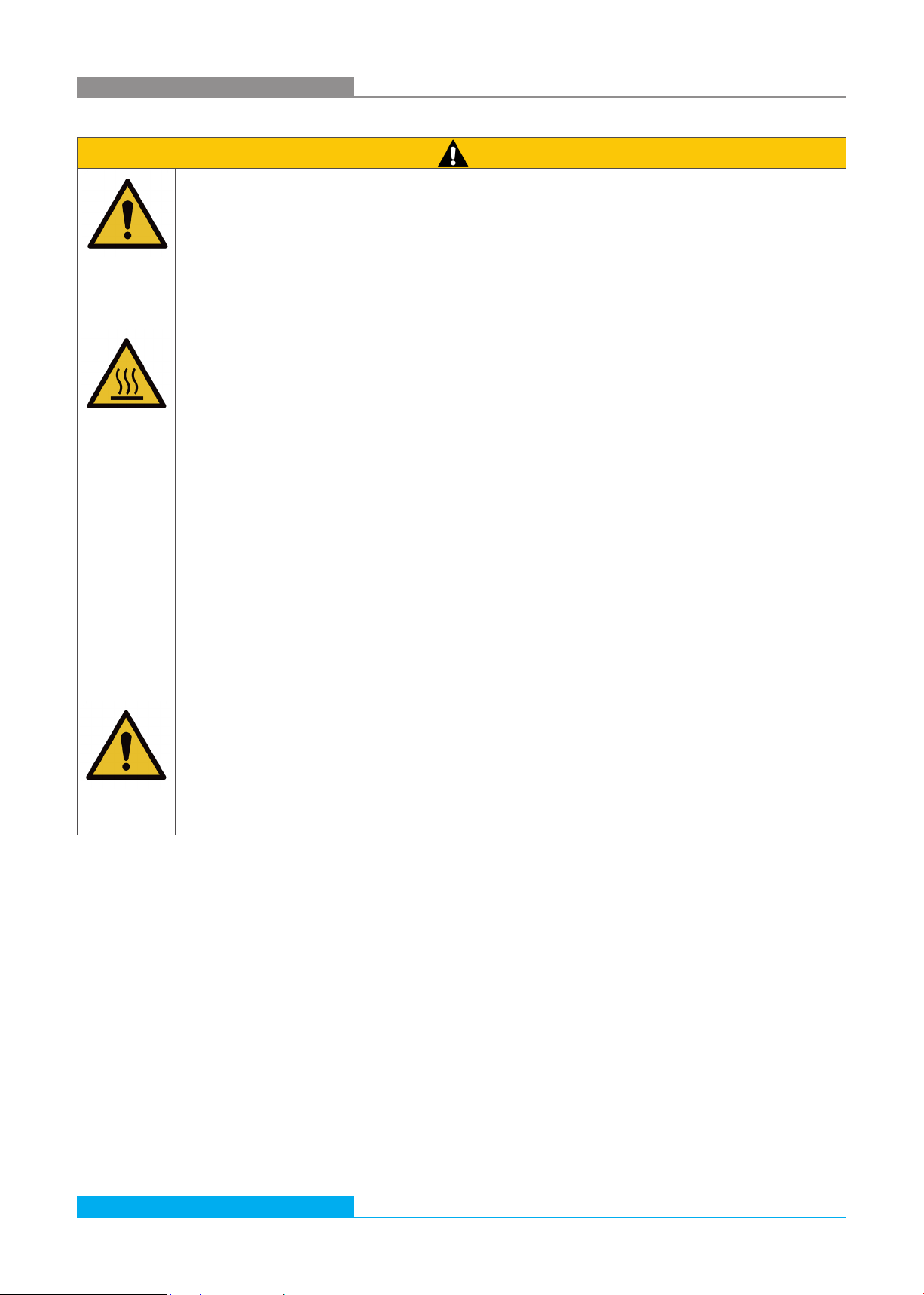
CAUTION
Leaked hydraulic oil
Environmental hazard / risk of slipping.
›In case of spills, cover the oil-covered surface immediately with an oil-binding medium.
›Then immediately dispose of the oil-binding medium according to the national environmental regulations.
Ignition hazard
Risk of electrostatic charge by poorly conducting hydraulic fluid.
›If the electrical conductivity of the hydraulic fluid is not known, please contact the manufacturer of the
hydraulic fluid.
Risk of burns
Contact temperatures according to DIN EN563 (3) and DIN EN13202 (4) may be exceeded during
operation.
›Allow the off-line filter unit to cool down before touching it.
Subject to change · Filter and recirculating pump unit UMPC2 045 · 0322 · EN
Page 8 www.argo-hytos.com
3. General instructions
For prevention of material damage and product damage
CAUTION
Danger due to improper handling
Property damage
›The off-line filter unit may only be used in accordance with Section 2.2, “Intended use”.
Leakage or spillage of hydraulic fluid
Environmental pollution and ground water contamination.
›Use oil binding agents in order to bind leaked hydraulic oil.
Risk of burns
Contact temperatures according to DIN EN563 (3) and DIN EN13202 (4) may be exceeded during
operation.
›Allow the off-line filter unit to cool down before touching it.
Contamination due to fluids and foreign bodies
Premature wear, malfunction, risk of damage, property damage.
›Ensure cleanliness during installation in order to prevent foreign bodies, such as welding beads or metal chips,
from entering the hydraulic lines, leading to premature wear or malfunction.
›Make sure that connections, hydraulic lines and attachment parts (e.g. gauges) are free from dirt and chips.
›Prior to commissioning, check that all hydraulic and mechanical connections are connected and tight,
and that all gaskets and seals of the plug connectors are correctly assembled and undamaged.
›For removal of lubricants and other contaminants, use residue-free industrial wipes.
›Make sure that all connections, hydraulic lines and attachment parts are clean.
›Ensure that no contaminants enter when closing the connections.
›Make sure that no detergents enter the hydraulic system.
›Do not use cotton waste or faying cleaning rags for cleaning.
›Do not use hemp as sealing agent.
Improper cleaning
Premature wear, malfunction, risk of damage, property damage.
›Close all openings with appropriate protective fittings to prevent penetration of detergents.
›Do not use aggressive cleaning agents for cleaning. Clean the product with a suitable cleaning fluid.
›Do not use a high-pressure cleaner.
›Do not use compressed air to clean function interfaces such as seal areas.

Subject to change · Filter and recirculating pump unit UMPC2 045 · 0322 · EN
Page 9
www.argo-hytos.com
4. Scope of delivery
This package includes:
›1 Oil Service Unit UMPC2 045
›1 Operating manual
Subject to change · Filter and recirculating pump unit UMPC2 045 · 0322 · EN
Page 10 www.argo-hytos.com
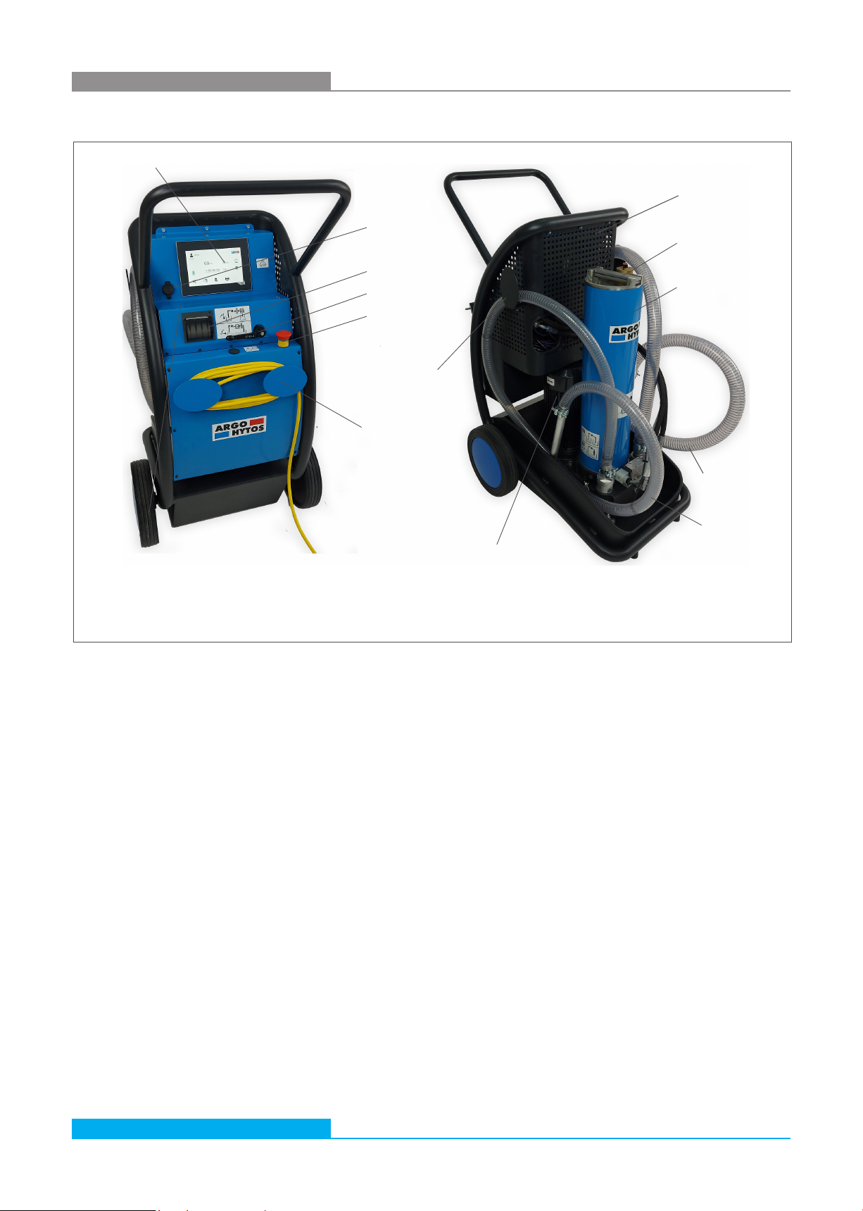
5.1 Component overview
5. About this product
Fig.1: Component overview
Transport rack
Ball valve
Suction hose
Hose holder
Pump with drive motor
Printer (option)
Touch Display
Touch display
The touch display is a control panel for steering the unit and visualizing the results. The control menu is described in chapter 9.
Printer
The built-in printer is an optional accessory which is used for printing of measurement reports.
Ball valve
The 3-way ball valve allows to determine whether the oil cleanliness monitoring is to be performed before or after the filter.
Safety button
The purpose of an emergency button is to stop the unit quickly when there is a risk of injury or the workflow must be stopped.
Hose holder
On both sides of the unit there are hose holders onto which the pressure hoses (suction and pressure side) can be wound for better
transport in case of non-use.
Cable holder
On the front of the unit there is a cable holder, onto which the 230V or 400V power cable can be wound for better transport in case
of non-use.
Pump drive / electric motor
The pump unit driven by an electric motor is responsible for media conveyance.
Safety button
Filter housing
with filter element
Return hose
Cable holder
Filter cover
USB port
Subject to change · Filter and recirculating pump unit UMPC2 045 · 0322 · EN
Page 11
www.argo-hytos.com
Transport rack
The transport rack is equipped with two wheels. This hand truck enables the unit to be transported without difficulty even
to inaccessible / narrow areas.
Filter cover
The filter cover closes the filter housing and serves, inter alia, for venting.
Filter housing with filter element
The filter housing contains the replaceable filter elements.
Changing the filter elements is described in "11.2 Changing the filter element" on page 34.
Suction hose
The suction hose is used to transfer the fluid from outside to the oil service unit.
Return hose
The return hose is used to transfer the fluid from the oil service unit to the outside.
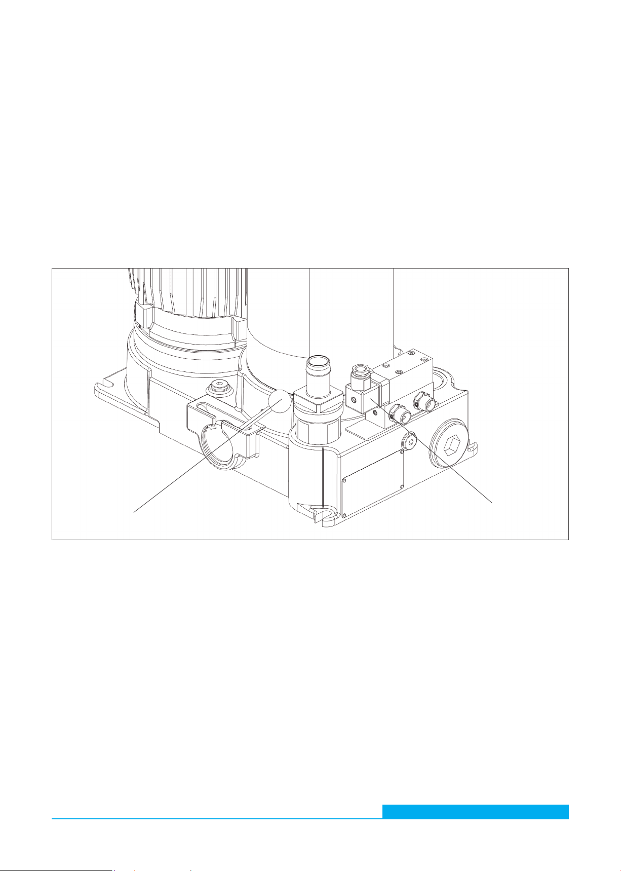
Fig.2: Component overview 2 (transport rack removed)
Switching lever
Differential
pressure
switch
Switching lever
This lever is used to switch the unit from "pumping" mode to "filtering".
Differential pressure switch
This switch monitors the pressure of the medium before and after the filter.
So if the pressure difference is too high (due to a dirty filter element), there will be an indication for the user on the main screen - see
also chapter 9.12.
Subject to change · Filter and recirculating pump unit UMPC2 045 · 0322 · EN
Page 12 www.argo-hytos.com
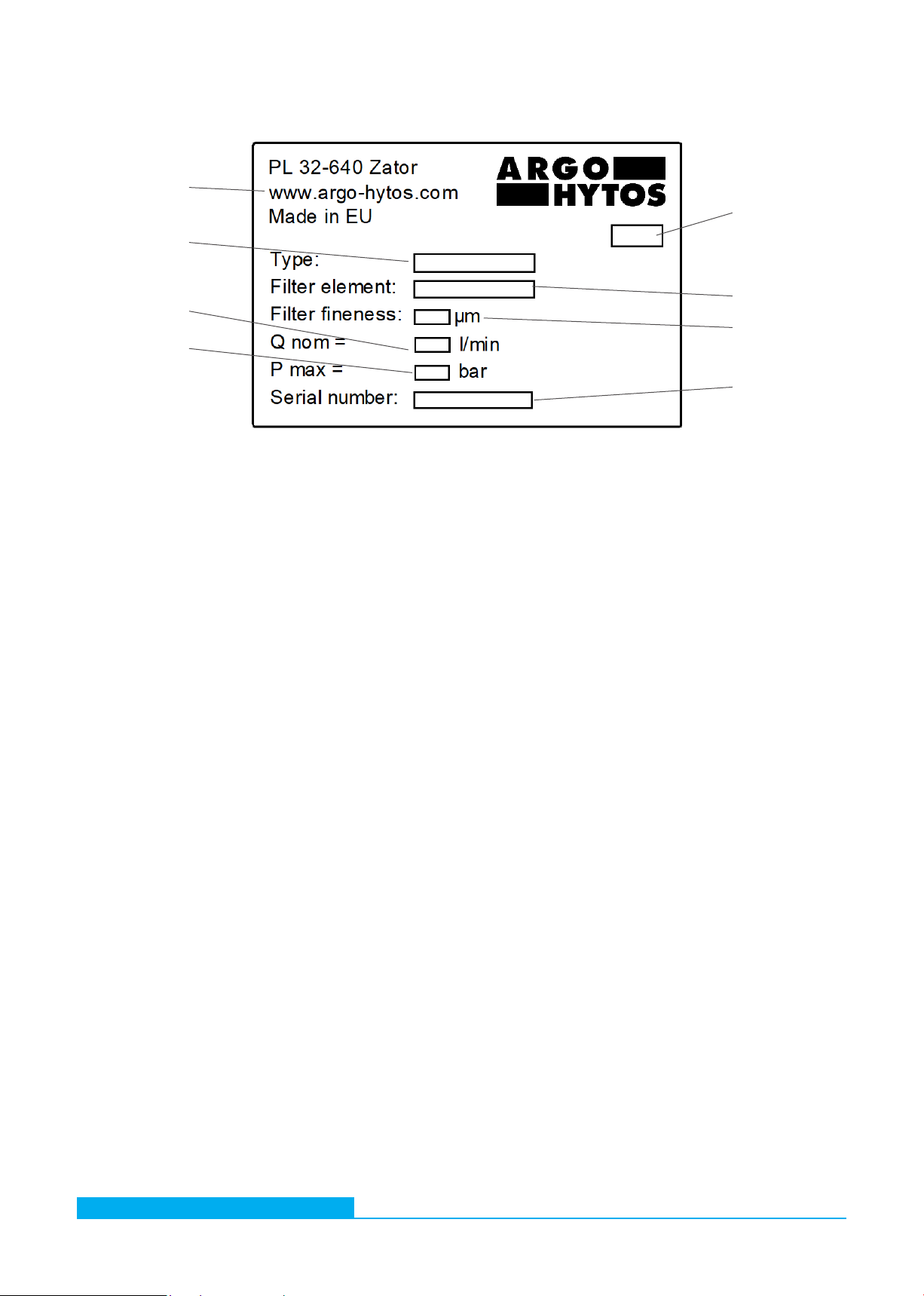
5.2 Identification of the product
Producer
address Manufacturing
date (encrypted)
Filter element type
Type
Filter element fineness
Nominal
flow volume
Serial
number
Fig.3: Nameplate
Max.
operating pressure
Subject to change · Filter and recirculating pump unit UMPC2 045 · 0322 · EN
Page 13
www.argo-hytos.com
6. Transport and storage
6.1 Transport
The unit should be transported horizontally as there is always a certain amount of oil inside the filter unit (in the filter as well as in
the pump), which will leak out during other transport and lead to soiling.
Observe the notes in Chapter 2 "Safety instructions".
Ensure that the unit is in a safe position (tipping hazard).
To prevent the leakage of residual oil, seal hoses at the open connections before transport.
During transport, secure the suction hose and the pressure hose in the brackets provided for this purpose in order to avoid possible
leakage of residual oil.
6.2 Storage
The UMPC2 045 filter unit should be stored in a confined space to protect it from humidity and condensation.
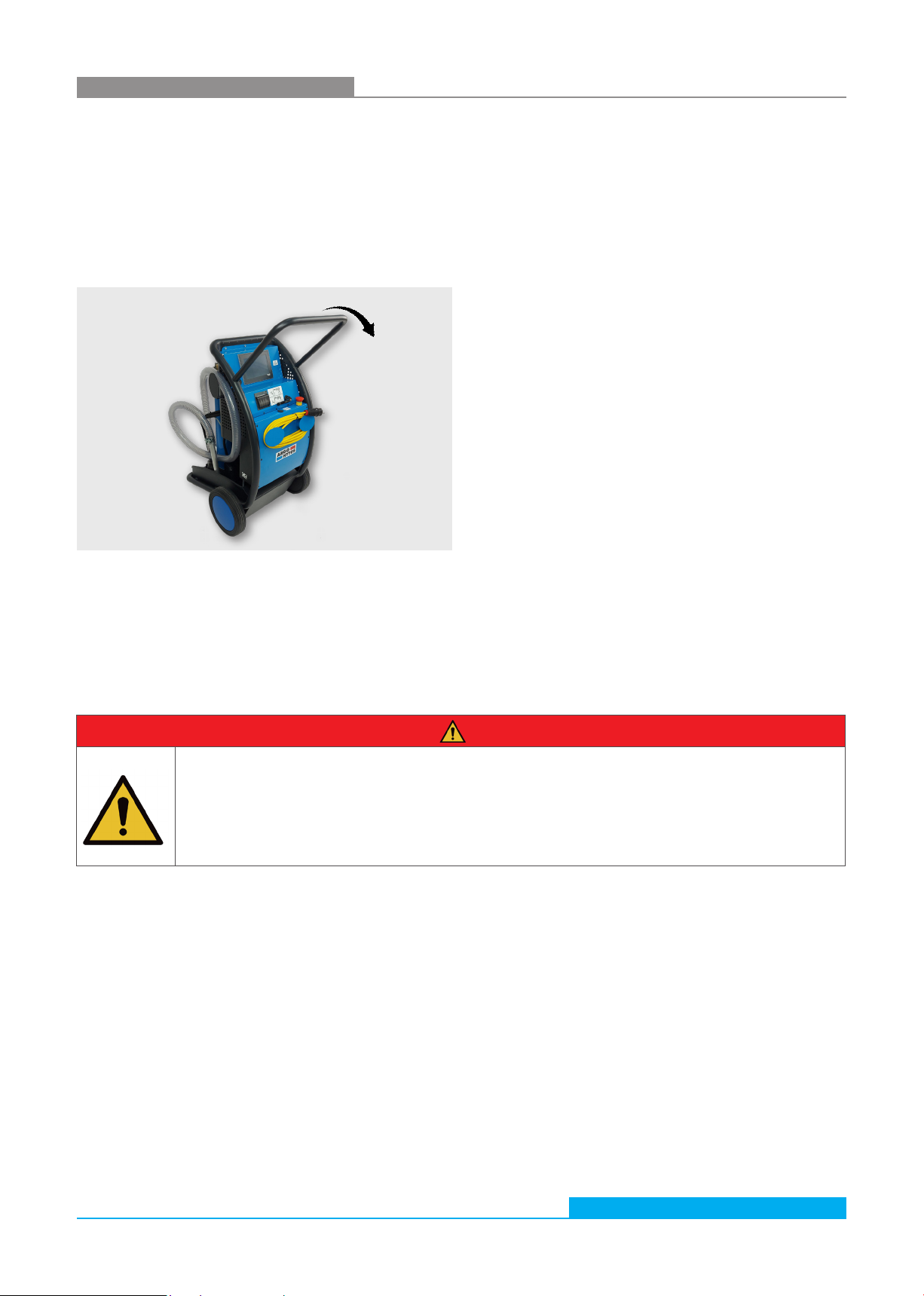
Fig. 4: Transport rack
The unit is mounted on a transport rack with two wheels.
This hand truck enables the unit to be transported without difficulty (weight: ~95 kg) even to inaccessible / narrow areas.
For transport, the unit can be rolled over the wheels by pushing the handle (see arrow) and transported to the destination.
DANGER
Risk of injury
Danger of chemical reactions
Chemical substances in the immediate vicinity of the filter unit can react and lead to the destruction of the device
and to injuries to persons in the immediate vicinity of the device.
›Storage in the immediate vicinity of chemically active substances such as acids, alkalis, salts, organic solvents
and rechargeable batteries is prohibited.
The ambient temperature during storage of the filter unit UMPC 045 should be between +0 °C and +50 °C at a maximum humidity
of 80%.
Before storage over a period of more than 6 months, the device should be filled with oil in order to preserve it against corrosion.

Subject to change · Filter and recirculating pump unit UMPC2 045 · 0322 · EN
Page 14 www.argo-hytos.com
7. Assembly
Let - prior to commissioning - an electrician check whether:
›the mains voltage matches with the voltage specified on the type plate of the motor,
›the power source has appropriately been secured (16 A),
›the cross-section is of sufficient size,
›cable and connection to the power source are in perfect condition.
The following steps are to be followed in detail:
›connect the 230V (or 400V) voltage plug to the local power supply.
WARNING
Risk of functional impairment
Faulty power supply
›Always consider the country-specific regulations.

Subject to change · Filter and recirculating pump unit UMPC2 045 · 0322 · EN
Page 15
www.argo-hytos.com
8. Commissioning
8.1 After switching on the motor-pump unit
›Check the filter unit for leaks.
›Check that the device is properly vented.
8.2 In case of power failure
In order to prevent unintentional starting of the unit, always switch off and unplug the unit.
8.3 Venting
To bleed the unit, carefully loosen the screw (2) on the ventilating valve (1). Clean the oil which will escape during the venting
process. Tighten the screw (2) on the ventilating valve (1)
NOTE
Do NOT leave the unscrewed ventilating valve - there is a risk of oil spillage through opened ventilating valve.
2
1
Fig.5: Venting
Subject to change · Filter and recirculating pump unit UMPC2 045 · 0322 · EN
Page 16 www.argo-hytos.com
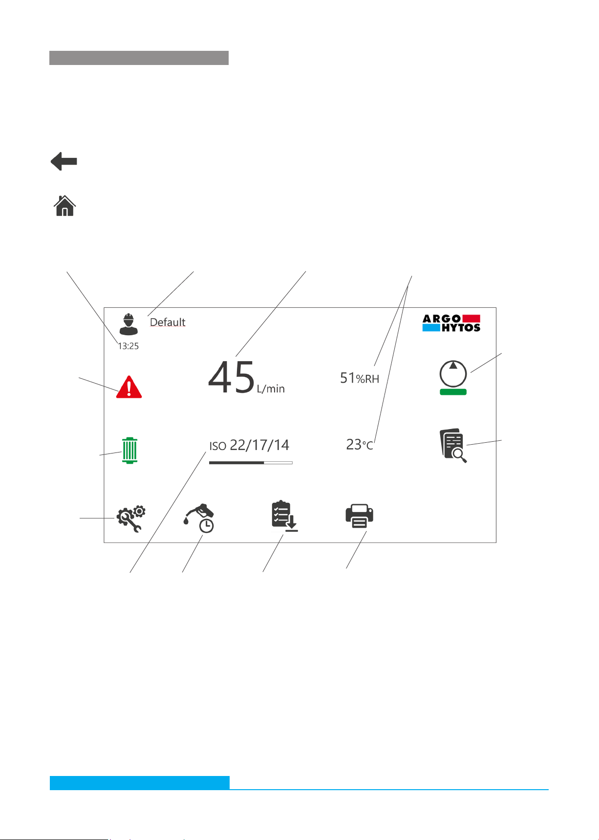
Fig.6: Start screen
Profile managementActual time Flow functions Temperature and relative
humidity
Pump
ON/OFF
Measure-
ment
data
Error
indication
Filter element
status
System
settings
Cleanliness class
functions
Dosing function Quick report Print
9. Menu structure and functions
The home screen of the touch display is shown in Fig. 6 By clicking on the appropriate field / icon, it is possible to activate the given
function or to go to the next screen with submenu. This chapter provides a description of the individual submenus and functions
included in the steering algorithm.
There are two navigation buttons for switching between the screens of the display:
back to the previous screen
back to the home screen
Subject to change · Filter and recirculating pump unit UMPC2 045 · 0322 · EN
Page 17
www.argo-hytos.com
9.1 Pump ON/OFF
Field for switching-on and off the motor-pump unit. The bar below the pump symbol changes its color from green into red when the
motor pump unit is running.
9.2 Actual time
Non-clickable field.
Shows the current time. The correct time can be set under the "System settings" button - see chapter 9.11.
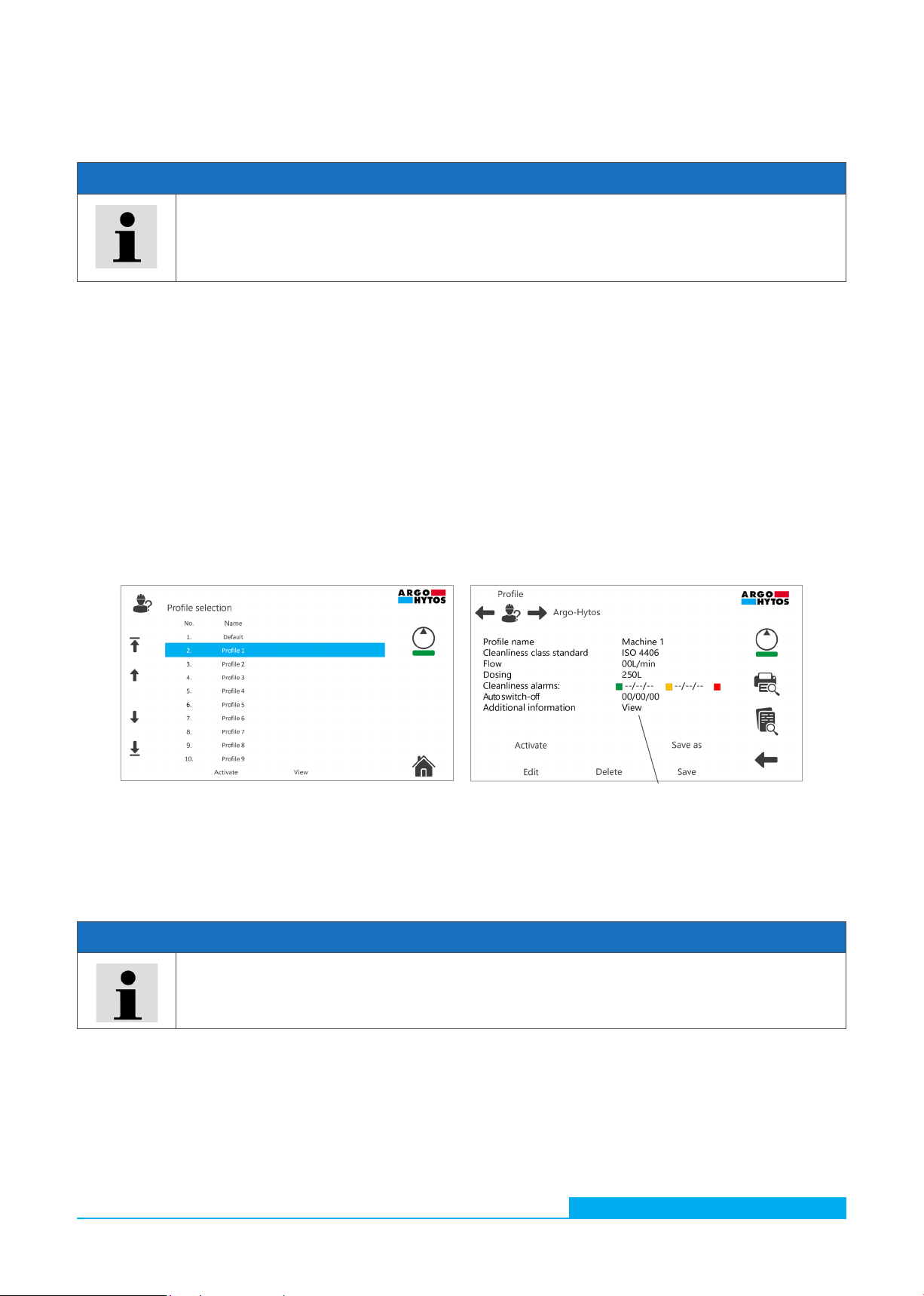
9.3 Profile management
Through this field there is a possibility to activate, view and / or edit single profiles.
The UMPC2 unit may be used for servicing of many systems which require completely different parameters and device settings.
Changing of working conditions does not result in the loss of the defined parameters. Operator can save the current settings in the
individual profile. Profiles can be defined for different customers, machines, working stations etc. Each profile consists of a name and
a set of individual settings. In the first step, the user gets to the "Profile selection" screen - Figure 7.1. In this screen, the selected
profile can be activated. The "View" button displays the profile editing screen - see Figure 7.2.
There is a default profile defined by the manufacturer. The name and settings of this profile cannot be changed.
Fig. 7.1: Profile selection screen Fig. 7.2: Profile ediition screen
NOTE
To stop the unit quickly in case of risk of injury, the safety button must be used. After the device has been
switched off with the safety button, the system requires some time (approx. 15-20 seconds) to be ready to be
switched on again.
The time counter that appears on the pump symbol indicates the remaining time until the system is ready for
activation.
Clickable field
to see full text of
additional information
NOTE
The operator can temporarily change all settings of the UMPC2. In doing so, the settings of the selected profile
are not changed until the changes are saved with the SAVE key. The settings of the DEFAULT profile cannot be
changed.
Subject to change · Filter and recirculating pump unit UMPC2 045 · 0322 · EN
Page 18 www.argo-hytos.com
In the "Profile" screen there are two additional buttons described below.
By clicking on this icon the printout / report preview is displayed. For more information about print / report
settings see chapter 9.11.1.
By clicking on this icon the "General data memory" is displayed. This button is also available in the home
screen. Each profile has its own general data memory. For more information see chapter 9.7.1.
9.4 Flow functions
Clickable field with the submenu showed in the Fig. 8.
Fig. 8: Submenu of flow functions
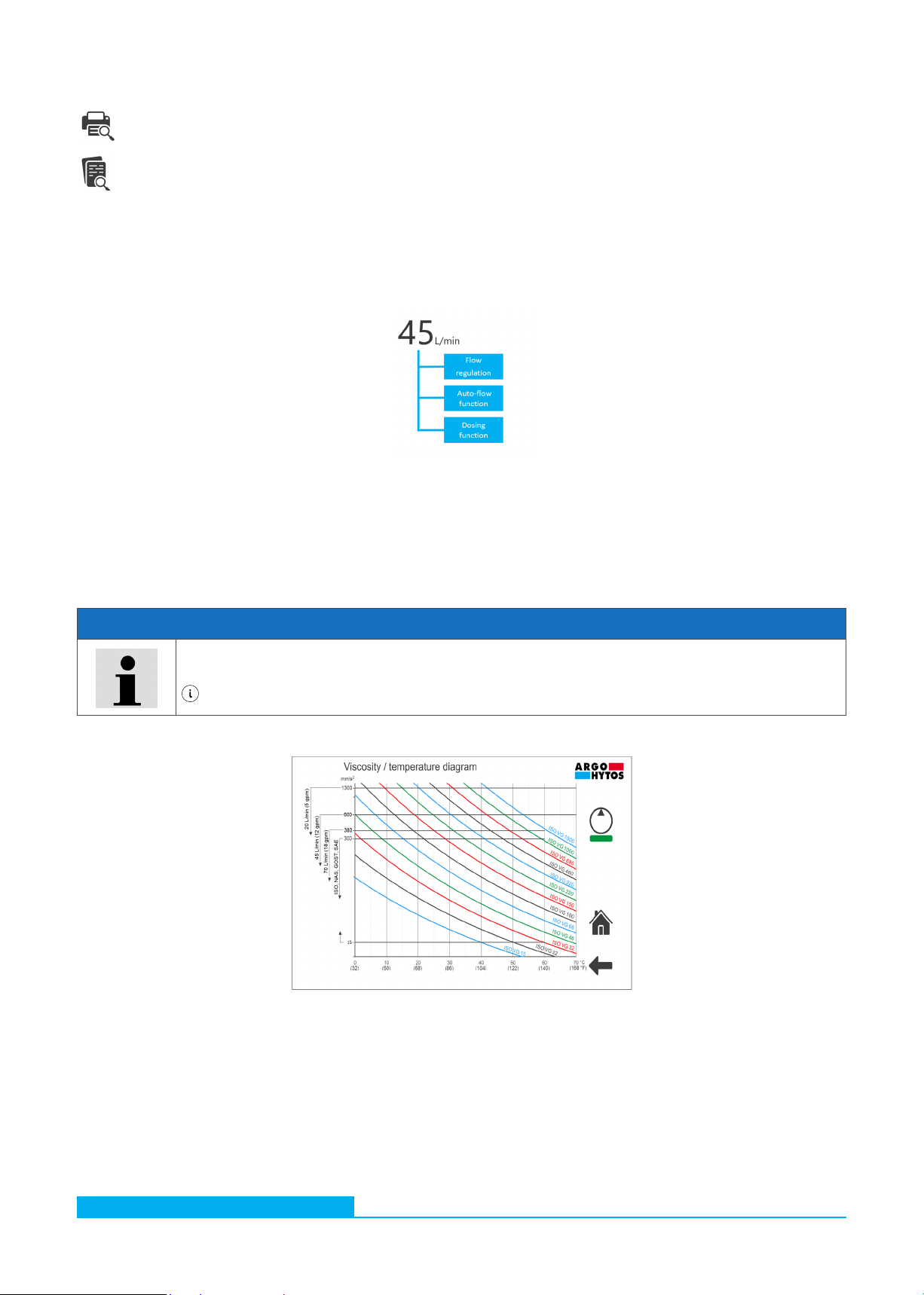
9.4.1 Flow regulation
Through this field there is a possibility to regulate the flow in the range of 20 -70 l/min.
NOTE
For flow regulation, the viscosity of hydraulic fluid must be taken into consideration. Compare the permissible
viscosity range of the device with the viscosity / temperature diagram which is available after clicking on the icon
in the flow regulation screen. See the Fig. 9.
Fig. 9: Screen with viscosity / temperature diagram

Subject to change · Filter and recirculating pump unit UMPC2 045 · 0322 · EN
Page 19
www.argo-hytos.com
9.4.2 Auto flow (AF) function
Function can be activated by clicking in the "Auto-Flow" field showed in the Fig. 10.
Fig. 10: Flow functions screen
The combination of letters AF with green bar is displayed in the home screen as an indication that the Auto-flow function is active,
see Fig.11.
Fig. 11: Auto-Flow function active
When the AF function is active, the flow of the UPMC2 unit is automatically reduced. The signal to activate the flow reduction
comes from the electrical clogging indicator. After detecting a certain pressure drop across the filter element, the flow rate is reduced
by approximately 5 l/min. For example, the initially defined flow of 50 l/min is reduced to approx. 45 l/min.
Working in this mode allows optimal utilization of the filter element. The dirt-holding capacity of 45 l/min defined for the nominal
flow rate is relatively larger at the reduced flow rate (pressure drop is lower at the smaller flow rate). So even if there is a signal from
the clogging indicator at a flow rate of 60 or 50 l/min, this signal may not be active at a flow rate of 20 l/min. Oil filtration can be
continued with the same filter element.
"Auto-flow" activation button
After clicking on the flow rate value, the system
settings screen is activated. From this level, the
unit of flow can be changed from liters/min to
gallons/min and vice versa.
Subject to change · Filter and recirculating pump unit UMPC2 045 · 0322 · EN
Page 20 www.argo-hytos.com
9.4.3 Dosing function
With this function the operator can define the amount of oil to be transferred. To set a dose of oil, click on the field for volume
definition showed in Fig.12. The keyboard will be activated and the required value can be entered.
Fig. 12: Dosing function settings
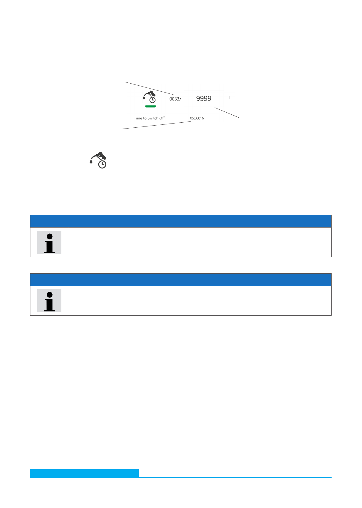
After clicking on the icon the function is activated. The green bar is displayed under the "Dosing" icon and two counters
are activated. The first counter, the "volume counter", shows the actual amount of transferred oil versus the pre-set value. The
second counter, the "time counter" shows the time remaining until the pump is stopped. When the pre-set volume is reached, the
pump of the UMPC2 is stopped automatically.
Current settings of this function can be permanently saved in the selected profile - see chapter 9.3.
NOTE
When working with the dosing function, the following sequence is recommended: Set the dosing value ->
activate the function -> activate the pump.
NOTE
The actual values can differ by approx. 3 % from the values set with the dosing function.
If the dosing function is activated for the unit with filter element but without oil filling, approximately 10 liters of
oil are required to fill the internal volume of the unit. This should be taken into account when setting the dosing
quantity.
9.5 Temperature and relative humidity results
Displays the current results of the temperature and relative humidity of the oil. If you click on one of these fields, the results will be
displayed in the form of charts. A separate submenu for managing the diagrams is shown in Fig.13.
Field for dosing volume definition
Volume counter
Time counter
Table of contents
Popular Service Equipment manuals by other brands


CEMO
CEMO DT-Mobil PRO PE 980l operating instructions

Bosch
Bosch DAS 3000 Unpacking, Assembly, Initializing

Speed Clean
Speed Clean BucketDescaler Operating & maintenance instructions

stellar labs
stellar labs TireMan 4110 owner's manual

Prolux
Prolux 600 215 Operating instruction

EDS
EDS LeakSeeker 89 Operation manual


