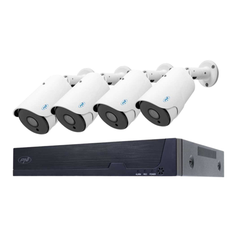
Infinique IHB703 Series User manual

2MP Night Vision Bullet Camera
Quick Installation Guide
English Version 1.0
IHB703 Series
w w w . i n f i n i q u e . c o m
Box Contents
Read Before You Use
1 x 2MP Night Vision Bullet Camera
1 x 60ft Video and Power Cable with Connectors
Mounting Screws, Installation Template
Power Adapter *, Quick Installation Guide
* Available only in 4 Camera Kits. Power adapter with
splitter is provided in 4 Camera Kits to power four cameras.
Key Points
Use the regulated UL / CSA / BIS approved power supply
which has been supplied with the camera pack. Use of a
non-regulated, non-conforming power supply can damage
this product and voids the warranty.
Before attempting to connect or operate this product,
read the instructions carefully and save it for reference.
All instructions should be followed for safe handling of the
product.
Camera should not be disassembled.
Camera should not be focused directly towards sun or
bright lights and where there are no obstructions.
Camera should be installed where vandals cannot easily
reach and the cable should be secured properly in ducts
to avoid damage.
Camera is for indoor and outdoor use, however when
installed outdoors sheltered location is recommended.
Camera should be operated within the given
temperature and humidity range.
Use the regulated UL / CSA / BIS approved power supply
which has been supplied with the camera pack. Use of a
non-regulated, non-conforming power supply can
damage this product and voids the warranty.
Use a damp cloth to clean the camera surface, do not
use any harsh cleaners.
The video and power supplied is rated for surface
mounting only.
Camera Features
1. Not intended for submersion in water. Installation in a
sheltered location recommended.
2. This camera includes an Auto Mechanical IR Cut Filter.
When the camera changes between Day/Night viewing
modes, an audible clicking noise may be heard from
the camera. This clicking is normal, and indicates that
the camera filter is working.
Disclaimer
Infinique reserve the right to modify product specifications and
prices without notice and without incurring any obligation.
© 2019 Infinique Worldwide Inc. Canada
Infinique is a registered trademark of Infinique Worldwide Inc.
Power Adapter
Two multi-camera power adapters options may be provided
that provided depending on the product configuration.
1. 2A 12V DC 4 Split Power Adapter to power 4 Cameras
2. 4A or 5A 12V DC 8 Split Power Adapter to power 8
Cameras
Camera Dimensions

Installing the Camera
Important
1. First test the camera prior to installing by connecting the
camera and cable to the DVR.
2. Plan how to run the cables either through or along the
wall or ceiling where drilling may be required. Cable
should be properly secured.
3. To keep the camera base flushed to the surface, run the
cable through the cable notch present at the base of the
camera.
Camera Connection
Camera Installation
Trouble Shooting
Problem Solution
Video captured is
too bright
Camera should not be directly pointed at
a source of light such as spot light or sun.
If so then move the camera to a different
location.
Check the brightness and contrast settings
of DVR and monitor.
Video captured is
too dark
Check if the DVR and monitor brightness
and contrast settings are set properly.
No Video Check the power supply of DVR and
Camera.
Check if the cables is secure between DVR
and Camera.
Check if the DVR is connected to the
monitor.
Check if monitor is on the correct input
channel.
The cameras are only compatible with
Infinique AHD DVRs.
No Video at Night The IR LEDs will turn on in low light
conditions, wait till the area becomes dark
and check to see if the IR LEDs are on.
Unclear or Foggy
Video
Clean the front cover of the camera with a
clean soft cloth to remove any dust
present.
Make sure that the video and power cable
run is void of any cuts and it is not close to
power lines.
Once the installation is complete, remove
the vinyl film from the camera lens.
Night video has
bright spots
If the camera is pointed through a
window, the night video will have bright
spots, in this case move the camera to a
different location.
Video and Power
cable is not long
enough
For alternate cabling refer to the Cable
Options section.
Cable Options
The video and power cable provided with the camera
covers a cable run distance of 60 feet. If the cable
provided is not sufficient, alternate cables can be used,
depending on the cable type as shown below.
1 RG59 Coaxial Siamese Cable
for Video and Power
300ft or 91m max cable
distance
2 RG59 Coaxial Cable for only
Video
1000ft or 305m max
cable distance
Key Points
If the cable run distance is above 300ft (91m), the power
source should be near the camera. If not the quality of
video will be affected.
A single stretch of cable should be used between the
Camera and the DVR. Do not use cable with multiple
connections.
If a video balun is used to extend the distance, it should
support a resolution of 2MP or above.
If the cable run distance used is too long, then you will
notice that the video is distorted and unclear and some-
time permanently black and white.
1. One end of the cable shall be connected to the camera
and the other end to the AHD DVR
2. On camera side, connect the male power connector
and the BNC Connector to the camera
3. On the DVR side, connect the BNC connector to one of
the video inputs on your DVR. There can be 4, 8 or 16
Video Inputs based on the AHD DVR Configuration.
4. On the DVR side connect the female power connector to
the power adapter splitter.
Camera
AHD DVR
BNC Connector
Power Connector
Power Adapter
1. Use the included mounting template mark and drill holes
for the mounting screws. Insert the anchors if installing on a
drywall.
2. Connect the cables as shown in the section ‘Camera
Connection’.
3. Feed the cable through the mounting surface. If you are
running the cables against a wall or ceiling, make sure to
pass the cable through the cable notch.
4. Using a Philips head screwdriver loosen the adjustment
screw. Adjust the camera position as needed.
5. Tighten the adjustment screw to secure the position.
6. Remove the vinyl film from the camera lens when your
installation is complete.

2MP Night Vision Dome Camera
Quick Installation Guide
English Version 1.0
IHD703 Series
w w w . i n f i n i q u e . c o m
Box Contents
Read Before You Use
1 x 2MP Night Vision Dome Camera
1 x 60ft Video and Power Cable with Connectors
Mounting Screws, Installation Template
Power Adapter *, Quick Installation Guide
* Available only in 4 Camera Kits. Power adapter with
splitter is provided in 4 Camera Kits to power four cameras.
Key Points
Use the regulated UL / CSA / BIS approved power supply
which has been supplied with the camera pack. Use of a
non-regulated, non-conforming power supply can damage
this product and voids the warranty.
Before attempting to connect or operate this product,
read the instructions carefully and save it for reference.
All instructions should be followed for safe handling of the
product.
Camera should not be disassembled.
Camera should not be focused directly towards sun or
bright lights and where there are no obstructions.
Camera should be installed where vandals cannot easily
reach and the cable should be secured properly in ducts
to avoid damage.
Camera is for indoor and outdoor use, however when
installed outdoors sheltered location is recommended.
Camera should be operated within the given
temperature and humidity range.
Use the regulated UL / CSA / BIS approved power supply
which has been supplied with the camera pack. Use of a
non-regulated, non-conforming power supply can
damage this product and voids the warranty.
Use a damp cloth to clean the camera surface, do not
use any harsh cleaners.
The video and power supplied is rated for surface
mounting only.
Camera Dimensions
1. Not intended for submersion in water. Installation in a
sheltered location recommended.
2. This camera includes an Auto Mechanical IR Cut Filter.
When the camera changes between Day/Night viewing
modes, an audible clicking noise may be heard from
the camera. This clicking is normal, and indicates that
the camera filter is working.
Disclaimer
Infinique reserve the right to modify product specifications and
prices without notice and without incurring any obligation.
© 2019 Infinique Worldwide Inc. Canada
Infinique is a registered trademark of Infinique Worldwide Inc.
Power Adapter
Two multi-camera power adapters options may be provided
that provided depending on the product configuration.
1. 2A 12V DC 4 Split Power Adapter to power 4 Cameras
2. 4A or 5A 12V DC 8 Split Power Adapter to power 8
Cameras
Camera Features

Installing the Camera
1. First test the camera prior to installing by connecting the
camera and cable to the DVR.
2. Plan how to run the cables either through or along the wall
or ceiling where drilling may be required. Cable should be
properly secured.
3. To keep the camera base flushed to the surface, run the
cable through the cable notch present at the base of the
camera.
Camera Connection
Camera Installation
Trouble Shooting
Problem Solution
Video captured is
too bright
Camera should not be directly pointed at a
source of light such as spot light or sun. If
so then move the camera to a different
location.
Check the brightness and contrast settings
of DVR and monitor.
Video captured is
too dark
Check if the DVR and monitor brightness
and contrast settings are set properly.
No Video Check the power supply of DVR and Cam-
era.
Check if the cables is secure between DVR
and Camera.
Check if the DVR is connected to the moni-
tor.
Check if monitor is on the correct input
channel.
The cameras are only compatible with In-
finique AHD DVRs.
No Video at Night The IR LEDs will turn on in low light condi-
tions, wait till the area becomes dark and
check to see if the IR LEDs are on.
Unclear or Foggy
Video
Clean the front cover of the camera with a
clean soft cloth to remove any dust pre-
sent.
Make sure that the video and power cable
run is void of any cuts and it is not close to
power lines.
Once the installation is complete, remove
the vinyl film from the camera lens.
Night video has
bright spots
If the camera is pointed through a window,
the night video will have bright spots, in this
case move the camera to a different loca-
tion.
Video and Power
cable is not long
enough
For alternate cabling refer to the Cable
Options section.
Cable Options
The video and power cable provided with the camera cov-
ers a cable run distance of 60 feet. If the cable provided is
not sufficient, alternate cables can be used, depending on
the cable type as shown below.
1 RG59 Coaxial Siamese Cable
for Video and Power
300ft or 91m max cable
distance
2 RG59 Coaxial Cable for only
Video
1000ft or 305m max
cable distance
Key Points
If the cable run distance is above 300ft (91m), the power
source should be near the camera. If not the quality of
video will be affected.
A single stretch of cable should be used between the
Camera and the DVR. Do not use cable with multiple
connections.
If a video balun is used to extend the distance, it should
support a resolution of 2MP or above.
If the cable run distance used is too long, then you will
notice that the video is distorted and unclear and some-
time permanently black and white.
1. One end of the cable shall be connected to the camera
and the other end to the AHD DVR
2. On camera side, connect the male power connector
and the BNC Connector to the camera
3. On the DVR side, connect the BNC connector to one of
the video inputs on your DVR. There can be 4, 8 or 16
Video Inputs based on the AHD DVR Configuration.
4. On the DVR side connect the female power connector to
the power adapter splitter.
Camera
AHD DVR
BNC Connector
Power Connector
Power Adapter
1. Use the included mounting template mark and drill holes
for the included mounting screws.
2. Rotate the camera base counter clockwise to separate it
from the ball camera, adjustment ring, and dome cover.
3. Connect camera as per section ‘Camera Connection’.
4. Feed the cable through the camera base. If you are run-
ning the cables against a wall or ceiling, pass the cable
through the cable notch. Mount the camera base to the
mounting surface using the screws. Insert the anchors if
installing on a drywall.
5. Place the adjustment ring over the dome cover, then
place both over the ball camera. Twist the adjustment ring
clockwise halfway onto the camera base. Do not tighten
all the way.
6. Move the camera to the desired position. While holding it
firmly in place, twist the adjustment ring the rest of the way
to secure it to the camera base. Holding the camera pre-
vents it from moving while securing the adjustment ring.
7. Remove the vinyl film from the camera lens when your
installation is complete.

1080p Hybrid AHD DVR
Quick Installation Guide
English Version 1.0
Hybrid AHD DVR
w w w . i n f i n i q u e . c o m
Step 3 - Connect Monitor
Camera
AHD DVR
BNC Connector
Power Connector
Power Adapter
Part A - DVR Physical Setup
Step 2 - Connect Cameras
Step 6 - Connect Power
Step 4 - Connect Router
Step 5 - Connect Mouse
1. Video and Power Cable are labelled indicating connec-
tion to camera or DVR. Connect the camera labelled
connector both video and power to the camera, and the
DVR labelled one to the video input on the DVR.
2. After connecting one side of the power connector to the
camera the other side of the connector shall be
connector to the 1x4 or 1x8 power splitter. The power
splitter will be connector to the power source.
The picture below explains the connectivity of all the ports of
the DVR. To setup the DVR follow the steps in the order listed.
1
4
5
2
3
DVR Back Panel may differ based on the DVR configuration.
However all ports will be present but in different locations. 4
Channel DVR back panel is shown, 8 and 16 Channels back
panels will have 8 and 16 video inputs to connect the cameras.
Monitors connected to the DVR can be either HDMI or VGA.
HDMI Cable is included in the pack to connect to the HDMI
Monitor. VGA cable is not included.
Connect the router to the DVR using the Ethernet Cable which is
included in the pack. For remote viewing and receive email
alerts a high speed interconnection is required. All other system
features can be used without an internet connection.
Connect the mouse which is included in the packing to the USB
port which is on the front side of the DVR. The mouse can be
used for navigating through the DVR system menu.
Connect the DVR to the power outlet using the power adapter
which is included in the DVR Pack.
Infinique reserve the right to modify product specifications and
prices without notice and without incurring any obligation.
© 2019 Infinique Worldwide Inc. Canada
Infinique is a registered trademark of Infinique Worldwide Inc.
This completes Part A, the physical setup of the DVR.

Step 6 - General System Configuration
Play Back and Search
Part B - DVR System Setup Mouse and Virtual Keyboard
After physical setup of the DVR is complete, the system setup
should be done. When the DVR is powered on, the setup
wizard will guide through the basic system settings required.
The system will prompt to create a username and password.
Enter a username and password which should be 8 digits
long. Record the username and password below and store it
in a secure place.
Username: Password:
Step 2 - Network Configuration
In the Network Configuration screen, unselect DHCP and
enter the IP Address of the DVR (default DVR IP Address will be
displayed), Subnet Mask and Gateway IP Address (Router IP
Address) of the network to which the DVR is connected.
Network Configuration should be setup correctly for proper
functioning of the remote access.
1. LEFT-CLICK: Menu Navigation: Click to open a menu option.
Split-screen Display: Double click will toggle between full-screen
and split-screen.
Live View: Click on a channel to
open Camera Quick Toolbar. 2.
RIGHT-CLICK:
Live View: Click to open Taskbar.
Menu Navigation: Click to exit
menus.
3. SCROLL WHEEL:
Menu Navigation: To scroll up and
down the menu content.
The Virtual Keyboard automatically
appears on the screen when data needs to be entered.
Step 1 - Username and Password
In General System Configuration, click on Date and Time tab
and enter date, time and time zone to ensure accurate time
on video recordings.
NTP: Enable NTP and Check NTP to
sync your system with an Internet
time server. Click Manual Update to
instantly update the time. Internet
connection is required to use NTP.
DST: Enable DST for auto Daylight Savings Time updates.
Step 3 - Email Setup
Email settings are required to receive the alert emails when
events happen. Internet connection is required to for the
email alerts to work. Enter the Email id and the other details
required.
Step 4 - IP Camera Setup
Analog HD Cameras are automatically configured. As this is a
Hybrid DVR, IP Cameras can also be connected. Additional
configuration will be required to setup the IP Cameras. Refer
the manual for instructions on how to setup IP Cameras.
This completes Part B, the basic system setup of the DVR.
Search allows you to search through the video recordings on
the hard drive. Click on the Search icon to start the search
and play back recordings. You can search by channel, date,
events and many more options. The
search results will be displayed on the
timeline from 00:00 to 24:00.
Click the Play button to start playback.
Control the playback with buttons on
Video Playback Controls.
Step 5 - Record Schedule
In the Record Schedule select Normal as recording mode.
Motion or Alarm can also be opted for. Refer manual for
instructions on Record Mode and Record Schedule.
DVR Features
Dimensions
Package Contents
Visit Infinique.com, to chat online, to send us email to ecom-
merce@infinique.com or to download quick guides, instruction
manuals, datasheets and software.
Need Help
Backup of Video Recordings
To back up video recordings from the DVR to a USB flash drive:
1. Insert a USB flash drive (not included) into a free USB port on
the DVR.
2. In the Search Detailed View Mode, check boxes next to
recordings you want to back up. The number of recordings
selected and total size information will be displayed at the
bottom right of the screen.
3. After selecting the files, click icon to save the video to
USB flash drive.
Refer manual for detailed instructions on Search, Playback
and Backup.

InfiViewCam Installation Manual
P a g e | 1
Overview
InfiViewCam 2.0.1 is compatible with Android Ver5.0 or above and iOS 7.0 and above. It can
support live view, remote playback, PTZ control, local playback, snap shot and push notifications,
etc. from DVR and NVR via 3G or above, or WIFI.
Installation
Search for the InfiViewCam App on Google Play Store for Android devices or App Store for iOS
devices and install on your smart phone. Run the app, it will display the live view screen as shown
below.
Add Recorder to Device List
To add recorder select the menu icon and select Device List from the menu, which will display
the Device Manager. Select the icon to add the new device, the add new device window
will be displayed.

InfiViewCam Installation Manual
P a g e | 2
Adding Recorder by Scanning QR Code
In the Add New Device window, scan the QR Code Sticker present on the recorder or Scan the
QR code from recorder Information menu. Once connected, all the channels will be
displayed.
Adding Recorder using Online Search
In the Add New Device window, Click on Online Search, all the recorders connected to the
same network will be listed in the Online Device display. Select the required recorder from the
list. Once connected, all the channels will be displayed.

InfiViewCam Installation Manual
P a g e | 3
Adding Recorder using Manual Add
In the Add New Device window, Click on Manual Add, and enter all the required parameters
for the recorder to be added to the Device List.
Edit Device
Under Device interface, click Device to view device information.
Edit device information.
Clicks save to save.
Remove devices
Under Device Manager interface, slide the device to left, and then click Delete to remove it.
IP Address/ID: IP Address of the Recorder
Media Port: 9000
User Name: admin (default user)
Password: Enter the recorder password
Click Save

InfiViewCam Installation Manual
P a g e | 4
Liveview
Click to go to Live View interface. Under Live View interface, click on top right to go to Devices
interface. Icons on Devices interface are shown in the table below:
Icons
Function
Devices
Channel
Select channel to do live view
Return to live view interface
Click device to select channels, and then click Start Live View icon to view the cameras. If it is
under multiple channels display mode, you can drag the cameras to reorder the windows.
Icons on Live View are shown below.
PTZ Control
Click to show PTZ control panel.
Icons
Function
Tab arrows to move camera side to side or up and down
Set speed
Set, call or delete preset point
Under PTZ control panel, press the arrows to move camera side to side or up and down.
Click Zoom +/- to Zoom In/Out;
Click Focus +/- to Focus In/Out;
Click Iris +/- to Iris In/Out.

InfiViewCam Installation Manual
P a g e | 5
Set/Call Preset Points
Press PTZ control arrows to move the camera to the requested place. Click to set preset points
(1—256). Click Set to complete. Slide up and down to select preset points. Click Call to call preset
point.
Image Quality Switch
Switch among Main stream, Sub stream and mobile stream.
Note:
Switch image quality will affect image quality of live view and recording on phones.
Zoom
Under Live View, double click windows to go to full screen, hold or separate fingers to zoom in or
zoom out.
Full Screen Display
Under Live View, flip mobile phones to go to full screen display.
Voice intercom
If the device supports voice intercom function, click button can use this function.
Select and delete the live view channel
Select and drag the channel to the upper side of the mobile phone screen, until the background
color of the upper side screen turn red and a garbage icon comes out. Then the channel selected
will be deleted
Remote Playback
Click to go to Remote Playback interface.
Start Playback
Under Remote Playback interface, click to go to Devices interface. Icons on Devices interface
Icons
Function
Select Channels to do playback
Devices
Channels
Return to Remote Playback interface
Select date and type from devices list on the top of Devices interface and click device name to
select channels you would like to replay. Then select Date to return to remote playback interface
to start playback.
Icons of Remote Playback
Icons
Function
Slow Play
/
Play/Pause
Fast Forward
Frame by Frame
Stop

InfiViewCam Installation Manual
P a g e | 6
Snapshot
Record
Mute on/off
Slide playback time bar can adjust playback time, and hold and drag playback windows can
reorder the windows.
Zoom
Double click to enlarge the window, and then hold or separate fingers to Zoom in/out.
Adjust Playback Time
During playback, click , under playback time bar to Zoom in/out time.
Full Screen Playback
During playback, flip mobile phones to enlarge to full screen.
Local Playback
Click to go to Local Playback interface.
Start local playback
Under local playback interface, select device from device list to go to recording files interface
and select the files you would like to replay. Icons of Local Playback
Icons
Function
Slow Play
/
Play/Pause
Fast Forward
Frame by Frame
Stop
Snapshot
Mute on/off
Remove recording files
Under Recording Files interface, click edit to edit, select one or multiple files which you would like
to remove. Click Delete to remove the files, if you would like to delete all files, click clear. Click
Done to quit.
Remove Devices
Under Local Playback interface, hold and move to the left until Delete button in Red appears,
click Delete to remove.
Zoom
Hold or separate fingers to do Zoom in/out on live view.
Full Screen Playback
During playback, flip mobile phones to enlarge to full screen.

InfiViewCam Installation Manual
P a g e | 7
Image Manager
Click to go to Image Manager Interface.
Under Image Manager Interface, you can view and email snapshots.
Delete Devices
Under Image Manager interface, hold and move to left until Delete button in Red appears, click
Delete to remove device.
Send Images
Please follow the following instruction to email images.
Instruction:
Under Image Manager Interface, select device to go to images interface.
Select images, and click .
Under pop-up email interface, input receiver's email address and email subject. Click Send to
complete.
Delete Images
Please follow the following instruction to remove multiple images or recording files.
Instructions:
Click Edit to select images you would like to remove.
Click Delete to remove or click Clear to clear images.
Image Manager
Click an image to enlarge it to full screen. You can click to display images automatically. Click
to remove images.
You can hold or separate fingers to zoom in/out images. Or double click to decrease or enlarge
images. Or slide the screen to view next image.
Alarm
Click to go to Alarm interface.
Under Alarm interface, you can set push notifications and view alarm information.
Push Notifications
Under Alarm interface, click to go to Push Set interface.
Select device and enable push notifications.
Alarm
Under Alarm interface, you can view alarm received.
Slide the alarm information to the left until Delete icon appears, and click Delete to remove.
Click Clear to clear all alarm information.

TEC-VS-219-1905-V01
Hybrid Digital Video Recorders
User Manual
Before attempting to connect or operate this product, read the instructions carefully and
save this manual for future use.
Important Safety Instructions
Carefully read the following safety instruction to avoid personal injuries and prevent the
equipment and other connected devices from being damaged.
RoHS

Hybrid DVR User Manual
2 TEC-VS-219-1605-V01
Power sources: Use the power supply included or as specified by the manufacturer. Never
operate the equipment by using unspecified power supply.
Never push objects of any kind through openings of DVR to avoid electric shock or other
accidents.
Do not place the equipment in dusty environment. Do not install the DVR in places that are
prone to dust.
Do not place the equipment under rain or humid environment like basement. If the
equipment is accidentally in contact with water, unplug the power cable and immediately
contact your local dealer.
Do not install near any heat sources such as radiators, heat registers, or other apparatus that
produce heat.
Keep the surface of the equipment clean and dry. Use soft damp cloth to clean the outer
case of DVR (do not use liquid aerosol cleaners).
Do not operate if any problems are found. If there are any strange smell or sounds from DVR,
unplug the power cable and contact the authorized dealer or service center.
Do not try to remove the upper cover.
Warning: Do not remove the cover of DVR to avoid electric shock.
Handle with care. If DVR does not work normally because of damage caused by dropping
or mishandling, contact the authorized dealer for repairs.
Note: Warranty is void in such cases.
Use standard lithium battery (Note: Use the batteries included or as specified by the
manufacturer). After cutting off the power supply, if the system clock does not work, replace
the standard 3V lithium battery on the main board.
Warning: Turn off DVR before replacing the batteries, or you may suffer from serious electric
shock. Properly dispose the used batteries as per local regulations.
Place the DVR equipment in a place with good ventilation. The DVR system includes HDD,
which produces large amount of heat during operation. As a result, do not block the
ventilation openings (on the top, bottom, both sides and the reverse side) for cooling the
system during operation. Install or put the equipment in the place with good ventilation. The
attached power adapter can only be used for one set of DVR. Do not connect more
equipment, or DVR may restart repeatedly because of insufficient power.
Protect the power cord from being walked on or pinched particularly at plugs, convenience
receptacles, and the point where they exit from the apparatus.
Unplug this apparatus. When a cart is used, use caution when moving the cart/apparatus
combination to avoid injury from tip-over.
Prevent the equipment from water dropping or splashing. Do not place objects containing
water, such as flower vase, on the equipment.

TEC-VS-219-1905-V01
TO REDUCE THE RISK OF ELECTRIC SHOCK, DO NOT REMOVE.
NO USER-SERVICEABLE PARTS INSIDE. REFER SERVICING TO QUALIFIED SERVICE PERSONNEL ONLY.
.
FCC For Class-A Digital Device
A CLASS-A digital device complies with Parts 15 of the FCC Rules.
Operation is subject to the following two conditions.
This device may not cause harmful interference.
This device must accept any interference received, including interference that may cause undesired
operations.
The lightning flash with an arrowhead symbol within an equilateral triangle is
intended to alert the user to the presence of un-insulated “dangerous voltage”
within the product’s enclosure that may be of sufficient magnitude to constitute a
risk of electric shock to persons.
The exclamation point within an equilateral triangle is intended to alert the user to
presence of important operating and maintenance (servicing) instructions in the
literature accompanying the appliance

TEC-VS-219-1905-V01
TABLE OF CONTENTS
IMPORTANT SAFETY INSTRUCTIONS................................................................................................................... 1
1. INTRODUCTION .............................................................................................................................................. 5
1.1 FEATURES.....................................................................................................................................................5
2. DVR OVERVIEW .............................................................................................................................................. 5
2.1 FRONT PANEL................................................................................................................................................5
2.2 REAR PANEL.................................................................................................................................................. 6
2.2 REMOTE CONTROLLER.....................................................................................................................................7
3. DVR CONNECTIONS ........................................................................................................................................ 8
3.1 HDD INSTALLATION ........................................................................................................................................ 8
3.2 DVR CONNECTIVITY DIAGRAM..........................................................................................................................9
3.3 POWER SUPPLY CONNECTION ...........................................................................................................................9
3.4 CAMERA CONNECTION ..................................................................................................................................10
3.5 MONITOR CONNECTION ................................................................................................................................10
3.6 USING THE SUPPLIED MOUSE .........................................................................................................................10
3.7 USING THE VIRTUAL KEYBOARD.......................................................................................................................10
3.8 PASSWORD ................................................................................................................................................. 11
4. DVR START UP...............................................................................................................................................12
4.1 START WIZARD ............................................................................................................................................ 12
4.2 NETWORK CONFIGURATION............................................................................................................................ 12
4.3 DATE AND TIME........................................................................................................................................... 13
4.4 IP CAMERA................................................................................................................................................. 14
4.5 DISK.......................................................................................................................................................... 16
4.6 RESOLUTION ............................................................................................................................................... 16
4.7 MOBILE ..................................................................................................................................................... 16
4.8 SUMMARY..................................................................................................................................................17
5. LIVE VIEW SCREEN OVERVIEW......................................................................................................................18
5.1 CAMERA QUICK TOOLBAR ..............................................................................................................................19
5.2 TASKBAR .................................................................................................................................................... 19
5.3 START MENU ..............................................................................................................................................20
5.4 UNLOCK AND LOCK SCREEN ............................................................................................................................20
5.5 SHUTDOWN................................................................................................................................................ 21
6 DVR SYSTEM SETUP ....................................................................................................................................... 22
6.1 CHANNEL ................................................................................................................................................... 22
6.1.1 Analog Channels............................................................................................................................... 23
6.1.2 IP Channels....................................................................................................................................... 23
6.1.3 Protocol Manage.............................................................................................................................. 24
6.2 LIVE .......................................................................................................................................................... 25
6.3 IMAGE CONTROL.......................................................................................................................................... 26

Hybrid DVR User Manual
TEC-VS-219-1905-V01
6.4 PTZ..........................................................................................................................................................27
6.4.1PTZ Control........................................................................................................................................ 28
6.5 MOTION .................................................................................................................................................... 29
6.6 PIR........................................................................................................................................................... 31
6.7 VIDEO COVER..............................................................................................................................................33
6.8 INTELLIGENT ............................................................................................................................................... 33
6.8.1 PID - Perimeter Intrusion Detection................................................................................................... 34
6.8.2 LCD - Line Crossing Detection............................................................................................................ 36
6.8.3 SOD - Stationary Object Detection .................................................................................................... 38
6.8.4 PD - Pedestrian Detection ................................................................................................................. 40
6.8.5 FD - Face Detection........................................................................................................................... 41
6.8.6 CC - Cross-Counting .......................................................................................................................... 43
6.8.7 Intelligent Analysis ........................................................................................................................... 45
6.8.8 Intelligent Schedule .......................................................................................................................... 46
7 RECORD .........................................................................................................................................................47
7.1 ENCODE.....................................................................................................................................................47
7.2 RECORD PARAMETERS ................................................................................................................................... 48
7.3 RECORD SCHEDULE....................................................................................................................................... 49
7.4 CAPTURE....................................................................................................................................................50
7.5 CAPTURE SCHEDULE .....................................................................................................................................50
8 ALARM........................................................................................................................................................... 51
8.1 MOTION .................................................................................................................................................... 51
8.2 I/O...........................................................................................................................................................51
8.3 PIR........................................................................................................................................................... 52
8.4 PTZ LINKAGE ..............................................................................................................................................52
8.5 EXCEPTION .................................................................................................................................................53
9 NETWORK......................................................................................................................................................54
9.1 GENERAL....................................................................................................................................................54
9.2 PPPOE...................................................................................................................................................... 55
9.33G ...........................................................................................................................................................56
9.4 PORT CONFIGURATION ..................................................................................................................................56
9.5 DDNS.......................................................................................................................................................57
9.6 EMAIL .......................................................................................................................................................57
9.6.1 Email Configuration.......................................................................................................................... 58
9.6.2 Email Schedule ................................................................................................................................. 59
9.7 FTP.......................................................................................................................................................... 60
10 DEVICE......................................................................................................................................................... 61
10.1 DISK........................................................................................................................................................ 61
10.1.1 Disk Group...................................................................................................................................... 62
10.1.2 S.M.A.R.T........................................................................................................................................ 62
10.2 CLOUD.....................................................................................................................................................63

Hybrid DVR User Manual
TEC-VS-219-1905-V01
11 SYSTEM........................................................................................................................................................ 65
11.1 GENERAL.................................................................................................................................................. 65
11.1.1 Date and Time ................................................................................................................................ 66
11.1.2 NTP Settings................................................................................................................................... 67
11.1.3 DST Settings ................................................................................................................................... 67
11.2 OUTPUT CONFIGURATION ............................................................................................................................68
11.2.1 LIVE-OUT ........................................................................................................................................ 68
11.3 MULTI-USER............................................................................................................................................. 69
11.3.1 Changing Password ........................................................................................................................ 69
11.3.2 Add New Users ............................................................................................................................... 70
11.3.3 Setting User Permissions................................................................................................................. 70
11.4 MAINTENANCE ..........................................................................................................................................72
11.4.1 Log ................................................................................................................................................. 72
11.4.2 Load Default................................................................................................................................... 73
11.4.3 Upgrade ......................................................................................................................................... 74
11.4.4 Parameter Management ................................................................................................................ 74
11.4.5 Auto Reboot ................................................................................................................................... 74
11.5 IP CAMERA MAINTAIN ................................................................................................................................ 75
11.5.1 Upgrade IP Camera ........................................................................................................................ 76
11.5.2 Load Default Settings for IP Camera ............................................................................................... 76
11.6 SYSTEM INFORMATION ................................................................................................................................76
11.6.1 Information .................................................................................................................................... 77
11.6.2 Channel Information....................................................................................................................... 77
11.6.3 Record Information......................................................................................................................... 78
11.6.4 Network State ................................................................................................................................ 78
12 SEARCH, PLAYBACK AND BACKUP................................................................................................................ 79
12.1 USING SEARCH FUNCTION............................................................................................................................ 79
12.2 SEARCH AND PLAY VIDEO IN GENERAL.............................................................................................................81
12.3 VIDEO CLIP BACKUP.................................................................................................................................... 81
12.4 EVENT SEARCH,PLAYBACK AND BACKUP..........................................................................................................83
12.5 EVENT PLAYBACK CONTROL .......................................................................................................................... 85
12.5.1 Sub-periods Playback...................................................................................................................... 85
12.6 SMART SEARCH AND PLAYBACK ..................................................................................................................... 86
12.7 SMART SEARCH AREA..................................................................................................................................87
12.8 PICTURE SEARCH AND VIEW .........................................................................................................................88
12.9 PICTURE PREVIEW CONTROL.........................................................................................................................90
13 REMOTE ACCESS VIA WEB CLIENT ............................................................................................................... 91
13.1 BASIC SYSTEM ENVIRONMENT REQUIREMENTS..................................................................................................91
13.2 WEB PLUGIN DOWNLOAD AND INSTALLATION................................................................................................... 91
13.2.1 IE/Chrome/Firefox Setup ................................................................................................................ 91
13.2.2 Mac Safari Setup ............................................................................................................................ 93
13.4 WEB CLIENT MANAGER............................................................................................................................... 94
13.4.1 Live Interface.................................................................................................................................. 94

Hybrid DVR User Manual
TEC-VS-219-1905-V01
13.4.2 Playback......................................................................................................................................... 96
13.4.3 Playback Control Buttons................................................................................................................ 97
13.4.4 Remote Setting............................................................................................................................... 98
13.4.5 Local Setting................................................................................................................................... 99
14 VIEWING BACKED UP VIDEO ON PC AND MAC .......................................................................................... 100
15 REMOTE ACCESS VIA MOBILE DEVICES...................................................................................................... 103
16 APPENDIX .................................................................................................................................................. 106
16.1 TROUBLESHOOTING .................................................................................................................................. 106
16.2 USAGE MAINTENANCE .............................................................................................................................. 107
16.3 ACCESSORIES (FOR REFERENCE ONLY)............................................................................................................ 108
This manual suits for next models
3
Table of contents
Popular Security System manuals by other brands
Honeywell Home
Honeywell Home TUXEDOW Quick installation guide

MARGO SUPPLIES
MARGO SUPPLIES GADFLY instruction manual
WindowMaster
WindowMaster WSK 501 Installation instruction

Lifemax
Lifemax 1601C installation instructions

i3 International
i3 International 6P16 Series Quick connection guide

thermastor
thermastor Santa-Fe Crawl Space Alert Installation
