E2S BExBG05 Series User manual

E2S Datasheet 1.4.3 v10a
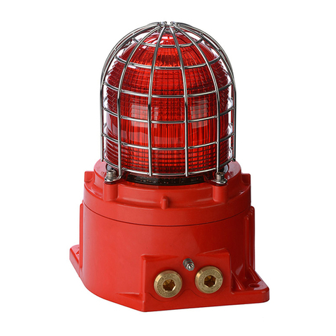
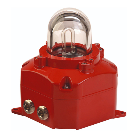
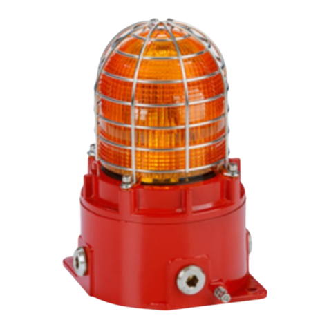
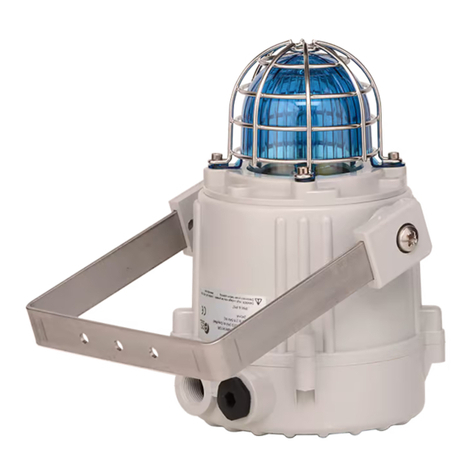
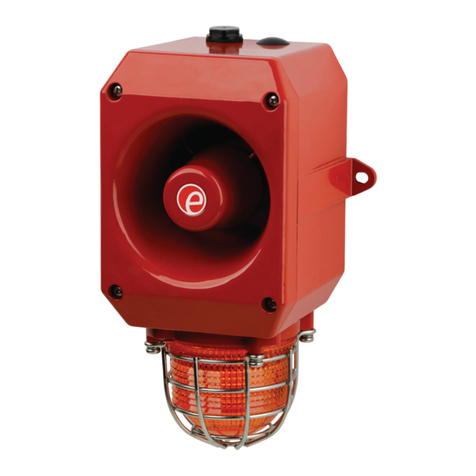
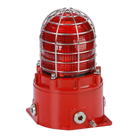
BExBG05 Xenon Beacon
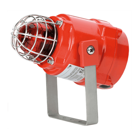
The flameproof BExBG05 Xenon beacons are suitable for Zone 1, 2, 21
& 22 applications.
The BExBG05 5 Joule beacons are ideal for eneral si nallin duties whilst their robust construction makes installation
in the harshest of environments possible. Additional features include automatic synchronisation on multi-beacon systems
and stainless steel uard and mountin bracket as standard.
The BEx ran e features enclosures manufactured from corrosion proof, marine rade copper free LM6 aluminium which is
phosphated and powder coated. All models have two M20 cable entries, lar e termination areas containin in & out
terminals (Ex de version only) and an in ress protection of IP66/67 (Ex d) and IP66 (Ex de).
Features:
•Automatic synchronisation on multi-beacon system.
•Beacons can be set to ‘flip-flop’ alternatin mode with
other units on multi-beacon systems.
•Xenon tubes mechanically secured a ainst shock
& vibration
•Glass lens & Stainless Steel uard
•Very lar e termination area.
•Ratchet adjustable stainless steel ‘U’ bracket.
•IN & OUT terminals (Ex de version only).
Approvals:
•ATEX certificate: KEMA 00ATEX2006,
EN 60079-0 : 2006, EN 60079-1 : 2007,
EN 60079-7 : 2003, EN 61241-0 : 2006,
EN 61241-1 : 2004
•IECEx certificate: IECEx KEM 10.0002,
IEC 60079-0 : 2004 (Ed4), IEC 60079-1 : 2007 (Ed6),
IEC 60079-7 : 2001 (Ed3), IEC 61241-0 : 2004 (Ed1),
IEC 61241-1 : 2004 (Ed1)
•GOST-R certificate: POCC GB.JB05.B02205
•Inmetro certificate: 10-IEx-0010
GOST-R
COMSEC PROTECTION SYSTEMS LTD.
UNIT 26, STADIUM BUSINESS PARK, • BALLYCOOLIN ROAD, • DUBLIN 11, • IRELAND
PHONE: +353 (0)1 8853008 • FAX: +353 (0)1 8853007
E2S Datasheet 1.4.3 v10a
Assemblies:
The products from the BEx ran e are available as
multiple unit assemblies with and without junction
boxes. See the BExP data sheet for further info.
259.00 mm
BExBG05D version BExBG05E version
246.00 mm
3 x 7mm dia. Mounting Holes
153.60 mm
145.00 mm
3 x 7 mm dia. Mounting Holes
153.60 mm
145.00 mm
Part codes:
Part Code: Classification:
BExBG05D** ATEX / IECEx:
II 2G Ex d IIC T4 Ta. -50°C to +70°C
II 2G Ex d IIC T5 Ta. -50°C to +55°C
II 2G Ex d IIC T6 Ta. -50°C to +40°C
II 2D Ex tD A21 IP67 T115°C
based on max. Ta. 70°C
GOST-R:
1ExdIICT4 Ta. -50° to +55°C
DIP A21 Ta T4
BExBG05E** ATEX / IECEx:
II 2G Ex de IIC T4 Ta. -50°C to +70°C
II 2G Ex de IIC T5 Ta. -50°C to +55°C
II 2G Ex de IIC T6 Ta. -50°C to +40°C
II 2D Ex tD A21 IP66 T115°C
based on max. Ta. 70°C
GOST-R:
2ExdeIICT4 Ta. -50° to +55°C
DIP A21 Ta T4
** = Volta e & lens colour reference:
Volta e options: 12DC, 24DC, 48DC, 115AC, 230AC
Lens colour options: -AM (Amber)
-BL (Blue)
-CL (Clear)
-GN (Green)
-RD (Red)
-YW (Yellow)
e. : BExBG05D115AC-AM
COMSEC PROTECTION SYSTEMS LTD.
UNIT 26, STADIUM BUSINESS PARK, • BALLYCOOLIN ROAD, • DUBLIN 11, • IRELAND
PHONE: +353 (0)1 8853008 • FAX: +353 (0)1 8853007
E2S Datasheet 1.4.3 v10a
E2S, Impress House, Mansell Road, London, UK, W3 7QH Telep one +44 20 8743 8880 www.e2s.com
No liability is accepted for any consequence of the use of this document. The technical specification of this unit is subject to chan e without notice due to our policy
of continual product development. All dimensions are approximate. This unit is sold subject to our standard conditions of sale, a copy of which is available on request.
Specification:
Ener y: 5 Joules (5Ws)
Flash rate: 1Hz (60 fpm)
Peak Candela: 34,812 cd
Effective Intensity cd: 105 cd*
Lens colours: Amber, Blue, Clear, Green, Red & Yellow
Volta es DC: 12vdc; 24vdc; 48vdc
Volta es AC: 115vac; 230vac
In ress protection: BG05D : IP66/67 BG05E : IP66
Housin material: Marine rade copper free LM6 Aluminium
Housin finish: Phosphated & powder coated finish - anti-corrosion.
Colour: RAL3000 Red (others available on request)
Cable entries: Dual M20 ISO (one stoppin plu included)
Terminals: 0.5 to 4.0mm² cables.
Line monitorin : Min. 500 Ohm 2w, or 3k3 Ohm 0.5w res. or diode within Exd enclosure (dc versions).
Tube life : Emissions are reduced to 70% after 8 million flashes
Wei ht : DC: 2.45k AC: 2.75k
Current consumption:
Version: Voltage range: Current:
12V dc 10-14V dc 750mA
24V dc 20-28V dc 300mA
48V dc 42-54V dc 180mA
115V ac 50Hz/60Hz +/-10% 140mA
230V ac 50Hz/60Hz +/-10% 55mA
Effective Candela lens colour factor:
Amber Blue Clear Green Red Yellow
0.51 0.12 1.00 0.49 0.15 0.86
*All candela data is representative of performance with clear lens at optimum volta e.
COMSEC PROTECTION SYSTEMS LTD.
UNIT 26, STADIUM BUSINESS PARK, • BALLYCOOLIN ROAD, • DUBLIN 11, • IRELAND
PHONE: +353 (0)1 8853008 • FAX: +353 (0)1 8853007

_______________________________________________________________________________________________________________________________
EuropeanSafetySystemsLtd. Impress House, MansellRoad, Acton, London W37QHsales@e-2-s.com Tel: +44 (0)208 743 8880
www.e-2-s.com Fax: +44 (0)208 740 4200
DocumentNo. IS2458-PIssue E23-02-10 Sheet1of 4(1)
INSTRUCTIONMANUAL(ATEX/IECEx)
BExBG05DFlameproofXenonBeacons
ForuseinFlammableGasand DustAtmospheres
1)Introduction
TheBExBG05Disaflameproofbeaconwhichiscertified to
meet therequirementsoftheATEXdirective94/9/ECandthe
IECExscheme.Thebeaconproducessynchronisedvisual
warningsignalsandcan be used inhazardousareaswhere
potentiallyflammablegasanddustatmospheresmaybe
present. TheBExBG05Dhasaflashenergylevelof 5joules
andcan be usedinZone1andZone2areaswithgasesin
groupsIIA, IIBandIICandTemperatureClassificationsofT1,
T2,T3andT4.Theunitcan alsobe usedinatemperature
classificationT5,iftheupperambienttemperatureis
restrictedto+55ºCandT6iftheupperambienttemperature
isrestricted to+40ºC.Theunitcan be usedinZone21 and
Zone 22areasforcombustibledustsand hasan IPratingof
IP67 andasurfacetemperatureratingof T115ºCorT100ºC
iftheupperambienttemperatureisrestrictedto+55ºCand
T85ºCiftheupperambienttemperatureisrestrictedto
+40ºC.
2)Marking
All unitshavearatinglabel,whichcarriesthefollowing
important information:-
UnitType No. BExBG05D
Input Voltage: DC Units12Vor24Vor48V
ACUnits230Vor115V
Codes: ExdIICT4forTa–50ºCto+70ºC
ExdIICT5forTa–50ºCto+55ºC
ExdIICT6forTa–50ºCto+40ºC
ExtDA21IP67T115ºCbased onmax. Taof+70ºC
CertificateNo’s KEMA00ATEX2006
IECExKEM10.0002
“Warnings” DONOTOPENWHENANEXPLOSIVE
GAS ORDUSTATMOSPHEREISPRESENT
COVERBOLTSCLASS A4-80
USE HEATRESISTINGCABLES ANDCABLEGLANDS
(Rated 110ºC)ATAMB. TEMPERATURES OVER40ºC
YearofConstruction/
SerialNo. i.e. 10 / 1DB13000001
3) TypeApprovalStandards
ThebeaconhasECTypeExaminationandIECExcertificates
issuedbyKEMAandhavebeenapprovedtothefollowing
standards:-
EN60079-0:2006 IEC60079-0:2004(Ed4) General Requirements
EN60079-1:2007 IEC60079-1:2007 (Ed6) Flameproof Enclosure‘d’
EN61241-0:2006 IEC61241-0:2004(Ed1)DustGeneral
Requirements
EN61241-1:2004 IEC60079-1:2004(Ed1)DustEnclosurestD
4) Installation Requirements
Thebeaconsmustbe installedinaccordancewiththelatest
issuesof therelevantpartsof theEN60079 standardsorthe
equivalentIECstandards–Selection,Installationand
maintenanceofelectricalapparatusforuseinpotentially
explosiveatmospheres(otherthanminingapplicationsor
explosiveprocessingandmanufacture):-
EN60079-14:2008 ElectricalInstallationsinHazardous
IEC60079-14:2007 (Ed4) Areas(otherthan mines)
EN60079-10:2003 Classification of HazardousAreas
IEC60079-10:2008 (Ed1)
Theinstallationoftheunitsmustalsobeinaccordancewith
anylocalcodesthatmayapplyandshouldonlybe carried
outbyacompetentelectricalengineerwhohasthe
necessarytraining.
5) Zones,Gas Group, Category,IPRating and
TemperatureClassification
TheBExBG05DbeaconshavebeencertifiedExdIICT4for
Ta–50ºCto+70ºC, ExdIICT5forTa–50ºCto+55ºCand
ExdIICT6forTa–50ºCto+40ºCforgasandIP67T115ºC
basedonmax. Taof+70ºC. Thismeansthat theunitscan
beinstalledinlocationswiththefollowing conditions:-
Area Classification Gas:
Zone1
Explosivegasairmixturelikelytooccurin
normaloperation.
Zone2
Explosivegasairmixturenotlikelytooccur,
andifit does, it willonlyexist forashort time.
GasGroupings:
GroupIIA
Propane
GroupIIB
Ethylene
GroupIIC
HydrogenandAcet
ylene
TemperatureClassification:
T1
400
o
C
T2
300
o
C
T3
200
o
C
T4
135
o
C
T5
100
o
C
Amb. +55ºC
T6
85
o
C
Amb. +40ºC
0518
II 2G/D
Epsilonx
Equipment Groupand
Category:
CEMarking
Notified BodyNo.
COMSEC PROTECTION SYSTEMS LTD.
UNIT 26, STADIUM BUSINESS PARK, • BALLYCOOLIN ROAD, • DUBLIN 11, • IRELAND
PHONE: +353 (0)1 8853008 • FAX: +353 (0)1 8853007
_______________________________________________________________________________________________________________________________
EuropeanSafetySystemsLtd. Impress House, MansellRoad, Acton, London W37QHsales@e-2-s.com Tel: +44 (0)208 743 8880
www.e-2-s.com Fax: +44 (0)208 740 4200
DocumentNo. IS2458-PIssue E23-02-10 Sheet2of 4(2)
Area Classification Dust:
Zone21
Explosivedustairmixturelikelytooccurin
normaloperation.
Zone22
Explosivedust airm
ixturenot likelytooccur, and
ifit does, it will onlyexist forashort time.
IPRating: IP67 T115ºCTa< +70ºC
T100ºCTa< +55ºC
T85ºCTa< +40ºC
EquipmentCategory: 2G/D
AmbientTemperatureRange: -50°Cto+70°C
(T5=+55ºC)
(T6=+40ºC)
6) Beacon Location and Mounting
Thelocationof thebeaconsshouldbemadewithdueregard
totheareaoverwhichthewarningsignalmustbe visible.
Theyshouldonlybefixedtoservicesthatcan carrythe
weight oftheunit.
Thebeaconsshouldbesecurelyboltedtoasuitablesurface
usingthe7mm diameterboltholesinthestainless steelU
shaped mountingbracket(see figure1).Therequired angle
can be achieved bylooseningthetwolarge bracket screwsin
thesideoftheunit, whichallowadjustmentofthebeaconin
stepsof 18°.Oncompletionoftheinstallation thetwolarge
bracketadjustmentscrewsonthe sideoftheunitmustbe
fullytightened toensurethat theunitcannot moveinservice.
SAFETYWARNING:
Theflashdomeguardmustnotberemovedfromtheunit
atanytime.
7) Access to theFlameproofEnclosure
Inordertoconnecttheelectricalsupplycablestothebeacon
itisnecessarytoremovetheflameproofcovertogainaccess
totheflameproofchamber.Toachievethisremovethefour
M6hexagonsocketheadscrews(see figure2)andwithdraw
theflameproofcovertakingextremecarenottodamagethe
flameproofjointsintheprocess.
Notethefour M6screwsareClass A4-80 stainlesssteel
andonlyscrewsofthiscategorycanbeusedonthe
beacons. Itisthereforeimportantthatthesescrewsand their
springwashersarekept inasafeplaceduringinstallation.
Oncompletionofthecablewiringinstallationtheflameproof
jointsshouldbe inspected toensurethattheyareclean and
thattheyhavenotbeendamaged duringinstallation.Also
checkthattheearthbondingwirebetweenthetwocasting
sectionsissecureandthe‘O’ringsealisinplace.When
replacingtheflameproofcovercastingensurethat it issquare
withtheflameproofchambercastingbeforeinserting.
Carefullypushthecoverinplaceallowingtimefortheairto
be expelled.Onlyafterthecoverisfullyinplaceshouldthe
fourM6StainlessSteelA4-80coverboltsandtheirspring
washerbe inserted andtightened down.If thecoverjams
whileitisbeinginserted,carefullyremoveitandtryagain.
Neverusethecoverboltstoforcethecoverintoposition.
8) PowerSupplySelection
Itisimportantthatasuitablepowersupplyisusedtorun the
beacons.Thepowersupplyselected musthavethe
necessarycapacitytoprovidetheinputcurrenttoall ofthe
beacons
Thefollowingtableshowsthe inputcurrenttakenbythe
variousbeacons:-
UnitType NominalI/PInput Max.
VoltageCurrentI/P
Volts
BExBG05D 12VDC 750mA 15V
BExBG05D 24VDC 300mA 30V
BExBG05D 48VDC 180mA 58V
BExBG05D 230VAC55mA 253V
BExBG05D 115VAC140mA 126V
Theinputcurrentwill varyaccording tothe voltageinput
level.The currentlevelsshownabovearefornominalinput
voltage.The12V,24Vand48VDC unitshaveaconverter
circuitandthereforetheinputcurrentlevelwilldecrease
slightlyastheinputvoltage inincreased andwill increase
slightlyastheinput voltage isreduced.
Theabovetablealsoshowsthe maximumvoltagesatwhich
thebeaconscan be operated.
Flashdome
Guard
Flameproof
Chamber
Flameproof
Cover
S/SBracket
Figure1
4off M6CoverScrews
ExternalEarth
Terminal
Figure2
COMSEC PROTECTION SYSTEMS LTD.
UNIT 26, STADIUM BUSINESS PARK, • BALLYCOOLIN ROAD, • DUBLIN 11, • IRELAND
PHONE: +353 (0)1 8853008 • FAX: +353 (0)1 8853007
_______________________________________________________________________________________________________________________________
EuropeanSafetySystemsLtd. Impress House, MansellRoad, Acton, London W37QHsales@e-2-s.com Tel: +44 (0)208 743 8880
www.e-2-s.com Fax: +44 (0)208 740 4200
DocumentNo. IS2458-PIssue E23-02-10 Sheet3of 4(3)
9) CableSelection
Whenselectingthecablesizeconsiderationmustbegivento
theinputcurrentthateachunitdraws(see tableabove),the
numberofbeaconsonthelineandthelengthofthecable
runs.Thecablesizeselected musthavethenecessary
capacitytoprovide theinputcurrenttoallofthebeacons
connected totheline.
SAFETYWARNING: IftheBExBG05Dbeaconsareusedat
highambienttemperatures,i.e.over+40ºC,thenthecable
entrytemperaturemayexceed+70ºCandthereforesuitable
heatresistingcablesmustbe used,witharated service
temperatureofat least 110ºC.
10) Earthing
BothACandDCbeaconunitsmustbeconnectedtoagood
qualityearth.Theunitsareprovided withinternaland
externalearthingterminalswhicharebothlocated onthe
terminalchambersectionoftheunit(see figures2and3).
Whenusingtheinternalearthterminalensurethatthe
stainless steelM4flatwasherisbetweentheincoming earth
wireandtheenclosure.
Whenusingtheexternalearthterminalacablecrimplug
must be used. Thecablelugshouldbelocatedbetweenthe
twoM5stainless steelflat washers. TheM5stainless steel
springwashermust be fixed betweentheouterflat washer
andtheM5stainless steelnut toensurethat thecablelugis
secured against looseningandtwisting.
Theinternalearthbondingwireensuresthatagoodquality
earthismaintained betweentheflameproof chambercasting
andtheflameproofcovercasting.
11) CableGlands
TheBExBG05Dbeaconshavedualcableglandentrieswhich
haveanM20 x1.5entrythreadasstandard.Onlycable
glandsapprovedforEx‘d’applicationscan be used,which
mustbe suitableforthetype ofcablebeingusedandalso
meettherequirementsoftheEx‘d’flameproofinstallation
standardEN60079-14:2008/ IEC60079-14:2007.
Whenonlyonecableentryisusedtheotheronemustbe
closedwithanEx‘d’flameproofblankingplug, whichmust be
suitablyapproved fortheinstallationrequirements.
Forcombustibledustapplications,thecableentrydeviceand
blankingelementsshall be intype ofexplosionprotection
increasedsafety"e"orflameproofenclosure"d"andshall
haveanIP6XratingaccordingtoEN60529:1992.
SAFETYWARNING: IftheBExBG05Dbeaconsareusedat
highambienttemperatures,i.e.over+40ºC,thenthecable
entrytemperaturemayexceed+70ºCandthereforesuitable
heat resistingcableglandsmust beused, witharated service
temperatureofat least 110ºC.
12) CableConnections
Thecableconnectionsaremade intotheterminalblockson
theelectronicpcbassemblylocatedintheflameproof
enclosure.Seesection7ofthismanualforaccesstothe
flameproofenclosure.Afour-wayterminalblockisprovided
onbothACandDC beacons.Thereforetherearetwolive
terminalsandtwoneutralterminalsfortheinputandoutput
wiringonACunits.OntheDC unitstherearetwo+ve
terminalsandtwo-veterminalsfortheinputandoutput
wiring.
Wireshavingacrosssectionalareaofupto2.5mm²can be
connected toeachterminalway.If an input andoutputwireis
required a2.5mm²wirecan be connectedtoeachterminal
way.Whenconnectingwirestothe terminalsgreatcare
shouldbe takentodressthewiressothatwhen thecoveris
inserted intothechamberthewiresdo notexertexcess
pressureontheterminalblocks.Thisisparticularlyimportant
whenusingcableswithlarge crosssectionalareassuchas
2.5mm².
13) SynchronisedOperation
All BExBG05Dbeaconsthatareconnected tothesame
supplylinewill haveasynchronised flashrateatoneflash
everysecond.Toensurethattheunitswill be synchronised
checkthat thepinheaderisnot fitted, i.e. thetwoheaderpins
arenot shorted together(see Figure4).
2off M20
CableEntries
InternalEarthTerminal
Figure3
InternalBonding
WireTerminal
BE
xBG05DBeaconCoverInternalView
Figure4
BExBG05D5JouleBeacons
Supply
Terminals
Flip / Flop
Pin Header
COMSEC PROTECTION SYSTEMS LTD.
UNIT 26, STADIUM BUSINESS PARK, • BALLYCOOLIN ROAD, • DUBLIN 11, • IRELAND
PHONE: +353 (0)1 8853008 • FAX: +353 (0)1 8853007
_______________________________________________________________________________________________________________________________
EuropeanSafetySystemsLtd. Impress House, MansellRoad, Acton, London W37QHsales@e-2-s.com Tel: +44 (0)208 743 8880
www.e-2-s.com Fax: +44 (0)208 740 4200
DocumentNo. IS2458-PIssue E23-02-10 Sheet4of 4(4)
14) Flip-Flop Operation
Twobeaconscan be mounted closetoeachothertoforma
flip-flopoperation,wherethebeaconswill flashalternately.
Toachievethismodeofoperation,fitapinheadertotheflip-
flopheaderpinsontheelectronics board,i.e.thetwoheader
pinsareshorted together,(see figure4)ononeofthetwo
beacons.Thefirstflashonthebeaconthathastheheader
fittedwill be delayed by½second.The twobeaconswill then
flashalternatelyevery½asecond.
15)End ofLineMonitoring (DC Units)
OntheBExBG05DDCbeacons,dcreverselinemonitoring
can be usedifrequired.All DC beaconshaveablocking
diode fittedintheirsupplyinputlines.Anend ofline
monitoringdiode oran endof linemonitoringresistorcan be
connectedacrossthe+veand–veterminals.If an end of line
resistorisuseditmusthaveaminimumresistancevalueof
3k3ohmsandaminimumwattage of0.5wattsoraminimum
resistancevalueof500ohmsandaminimumwattage of2
watts.
COMSEC PROTECTION SYSTEMS LTD.
UNIT 26, STADIUM BUSINESS PARK, • BALLYCOOLIN ROAD, • DUBLIN 11, • IRELAND
PHONE: +353 (0)1 8853008 • FAX: +353 (0)1 8853007
_______________________________________________________________________________________________________________________________
EuropeanSafetySystemsLtd. Impress House, MansellRoad, Acton, London W37QHsales@e-2-s.com Tel: +44 (0)208743 8880
www.e-2-s.com Fax: +44 (0)208740 4200
DocumentNo. BExBG05D(Gas-Dust)EnglishIssue E(FourSheets)23-02-10 (5)
INSTRUCTION MANUAL(ATEX/IECEx)(GBR)
BExBG05DFlameproofXenon Beacons
ForuseinFlammableGasand DustAtmospheres
2)Marking
All unitshavearatinglabel,whichcarriesthefollowing
important information:-
UnitType No. BExBG05D
Input Voltage: DC Units12Vor24Vor48V
ACUnits230Vor115V
Codes: ExdIICT4forTa–50ºCto+70ºC
ExdIICT5forTa–50ºCto+55ºC
ExdIICT6forTa–50ºCto+40ºC
ExtDA21IP67T115ºCbased onmax. Taof+70ºC
CertificateNo’s KEMA00ATEX2006
IECExKEM10.0002
“Warnings” DONOTOPENWHENANEXPLOSIVE
GAS ORDUSTATMOSPHEREISPRESENT
COVERBOLTSCLASS A4-80
USE HEATRESISTINGCABLES ANDCABLEGLANDS
(Rated 110ºC)ATAMB. TEMPERATURES OVER40ºC
4)Installation Requirements
Beaconsmust beinstalled inaccordancewiththefollowingor
equivalent standards.
EN60079-14:2008 ElectricalInstallationsinHazardous
IEC60079-14:2007 (Ed4) Areas(otherthan mines)
EN60079-10:2003 Classification of HazardousAreas
IEC60079-10:2008 (Ed1)
Installationshouldonlybe carried bycompetent personnel
andanylocalcodesofpracticeapplied.
5)Zones, GasGroup, Categoryand Temperature
Classification
Theunitscan be installed inlocationswiththefollowing
conditions:-
Area Classification Gas:
Zone1
Explosivegasairmixturelikelytooccurin
normaloperation.
Zone2
Explosivegasairmixturenotlikelytooccur,
andifit does, it willonlyexist forashort time.
GasGroupings:
GroupIIA
Propane
GroupIIB
Ethylene
GroupIIC
HydrogenandAcetylene
TemperatureClassification:
T1
400
o
C
T2
300
o
C
T3
200
o
C
T4
135
o
C
T5
100
o
C
Amb. +55ºC
T6
85
o
C
Amb. +40ºC
Area Classification Dust:
Zone21
Explosivedustairmixturelikelytooccu
rin
normaloperation.
Zone22
Explosivedustairmixturenotlikelytooccur,
andifit does, it willonlyexist forashort time.
IPRating IP67 T115ºCTa< +70ºC
T100ºCTa< +55ºC
T85ºCTa< +40ºC
EquipmentCategory: 2G/D
AmbientTemperatureRange:
-50°Cto+70°C
(T5=+55ºC)
(T6=+40ºC)
6)Beacon Location and Mounting
SeedrawingA
SAFETYWARNING: Theflashdomeguardmustnotbe
removedfromtheunitatanytime.
7)AccesstotheFlameproofEnclosure
SeedrawingB
Notethefour M6screwsareClassA4-80stainlesssteel
andonlyscrewsofthiscategorycanbeusedonthe
beacons. It isthereforeimportant thatthesescrewsandtheir
springwashersarekept inasafeplaceduringinstallation.
0518
II 2G/D
Ep
silonx
Equipment Groupand
Category:
CEMarking
Notified BodyNo.
COMSEC PROTECTION SYSTEMS LTD.
UNIT 26, STADIUM BUSINESS PARK, • BALLYCOOLIN ROAD, • DUBLIN 11, • IRELAND
PHONE: +353 (0)1 8853008 • FAX: +353 (0)1 8853007

_______________________________________________________________________________________________________________________________
EuropeanSafetySystemsLtd. Impress House, MansellRoad, Acton, London W37QHsales@e-2-s.com Tel: +44 (0)20 8743 8880
www.e-2-s.com Fax: +44 (0)20 8740 4200
DocumentNo. BExBG05D(Gas-Dust)EnglishIssue E(FourSheets)23-02-10 (6)
8)PowerSupplySelection
Thesystempowersupplymusthavethenecessarycapacity
toprovide theinput currenttoallofthebeaconsconnected to
thesystem.
Thefollowingtableshowstheinputcurrenttakenbythe
variousunits:-
UnitType NominalI/PInput Max.
VoltageCurrentI/PVolts
BExBG05D 12VDC 750mA 15V
BExBG05D 24VDC 300mA 30V
BExBG05D 48VDC 180mA 58V
BExBG05D 230VAC55mA 253V
BExBG05D 115VAC140mA 126V
Theabovetablealsoshowsthemaximumvoltagesatwhich
thebeaconscan be operated.
9)CableSelection
Cablesmustbe capableofhandlingthecurrentdrawnfrom
all oftheunitsontheline.
SAFETYWARNING: IftheBExBG05Dbeaconsareusedat
highambienttemperatures,i.e.over+40ºC,thenthecable
entrytemperaturemayexceed+70ºCandthereforesuitable
heatresistingcablesmustbe used,witharated service
temperatureofat least 110ºC.
10)Earthing
BothACandDC beaconunitsmust be connected toagood
qualityearth.Theunitsareprovided withinternaland
externalearthingterminalswhicharebothlocated onthe
terminalchambersectionoftheunit(see figures2and3).
Whenusingtheinternalearthterminalensurethatthe
stainless steelM4flatwasherisbetweentheincomingearth
wireandtheenclosure.
Whenusingtheexternalearthterminalacablecrimplug
must be used. Thecablelugshouldbelocatedbetweenthe
twoM5stainless steelflat washers. TheM5stainless steel
springwashermust be fixedbetweentheouterflat washer
andtheM5stainless steelnut toensurethat thecablelugis
secured against looseningandtwisting.
Theinternalearthbondingwireensuresthatagoodquality
earthismaintained betweentheflameproof chambercasting
andtheflameproofcovercasting.
11)CableGlands
TheBExBG05Dbeaconshavedualcableglandentrieswhich
haveanM20 x1.5entrythreadasstandard.Onlycable
glandsapprovedforEx‘d’applicationscan be used,which
mustbe suitableforthetype ofcablebeingusedandalso
meettherequirementsoftheEx‘d’flameproofinstallation
standardEN60079-14:2008/ IEC60079-14:2007.
Whenonlyonecableentryisused theotheronemustbe
closedwithanEx‘d’flameproofblankingplug, whichmust be
suitablyapproved fortheinstallationrequirements.
Forcombustibledust applications, thecableentrydeviceand
blankingelementsshall be intype ofexplosionprotection
increasedsafety“e”orflameproofenclosure“d”andshall
haveanIP6XratingaccordingtoEN60529:1992.
SAFETYWARNING: IftheBExBG05Dbeaconsareusedat
highambienttemperatures,i.e.over+40ºC,thenthecable
entrytemperaturemayexceed+70ºCandthereforesuitable
heat resistingcableglandsmust beused, witharated service
temperatureofat least 110ºC.
12)CableConnections
SeedrawingsCandD/ wiringdiagramE
13)Synchronised Operation
All BExBG05Dbeaconsthatareconnected tothesame
supplylinewill haveasynchronised flashrateatoneflash
everysecond.Toensurethattheunitswill be synchronised
checkthat thepinheaderisnot fitted, i.e. thetwoheaderpins
arenot shorted together(see Figure4).
14)Flip-Flop Operation
Twobeaconscan be mounted closetoeachothertoforma
flip-flopoperation,wherethebeaconswill flashalternately.
Toachievethismodeofoperation,fitapinheadertotheflip-
flopheaderpinsontheelectronics board,i.e.thetwoheader
pinsareshorted together,(see figure4)ononeofthetwo
beacons.Thefirstflashonthebeaconthathastheheader
fitted will be delayed by½second. Thetwobeaconswill then
flashalternatelyevery½asecond.
15)End ofLineMonitoring (DC Units)
OntheBExBG05DDCbeacons,dcreverselinemonitoring
can be usedifrequired.All DC beaconshaveablocking
diode fittedintheirsupplyinputlines.Anendofline
monitoringdiode oran endof linemonitoringresistorcan be
connectedacrossthe+veand–veterminals.If an end of line
resistorisuseditmusthaveaminimumresistancevalueof
3k3ohmsandaminimumwattage of0.5wattsoraminimum
resistancevalueof500ohmsandaminimumwattage of2
watts.
COMSEC PROTECTION SYSTEMS LTD.
UNIT 26, STADIUM BUSINESS PARK, • BALLYCOOLIN ROAD, • DUBLIN 11, • IRELAND
PHONE: +353 (0)1 8853008 • FAX: +353 (0)1 8853007
_______________________________________________________________________________________________________________________________
EuropeanSafetySystemsLtd. Impress House, MansellRoad, Acton, London W37QHsales@e-2-s.com Tel: +44 (0)20 8743 8880
www.e-2-s.com Fax: +44 (0)20 8740 4200
DocumentNo. BExBG05D(Gas-Dust)EnglishIssue E(FourSheets)23-02-10 (7)
Drawing A
Tighten screwtosecure.
Spænd skruen foratfastgøre.
Schroefaandraaien omvasttezetten.
Serrerlavispourune fixation sûre.
ZumSichernSchraube anziehen.
Stringerelaviteperilfissaggio.
Stramskruen foråfeste.
Aperteoparafusoparafixar.
Aprieteeltornilloparaasegurar.
Draåtskruven förattfästa.
Loosen screwtoadjust.
Løsnskruen forattilpasse.
Schroeflosdraaien omaftestellen.
Desserrerlavispourrégler.
ZumRegulieren Schraube lockern.
Allentarelaviteperpotereffettuarela
regolazione.
Løsne skruen foråjustere.
Desaperteoparafusoparaajustar.
Aflojeeltornilloparaajustar.
Lossaskruven förattjustera.
Lossen screw
toadjust
Tighten screw
tosecure
180º
Drawing B
Drawing C
NNLL
BExBG05D ACunits
Drawing D
BExBG05DDC units
++--
COMSEC PROTECTION SYSTEMS LTD.
UNIT 26, STADIUM BUSINESS PARK, • BALLYCOOLIN ROAD, • DUBLIN 11, • IRELAND
PHONE: +353 (0)1 8853008 • FAX: +353 (0)1 8853007
_______________________________________________________________________________________________________________________________
EuropeanSafetySystemsLtd. Impress House, MansellRoad, Acton, London W37QHsales@e-2-s.com Tel: +44 (0)20 8743 8880
www.e-2-s.com Fax: +44 (0)20 8740 4200
DocumentNo. BExBG05D(Gas-Dust)EnglishIssue E(FourSheets)23-02-10 (8)
Wiring DiagramE
N
L
LN LN LN
BExBG05D
ACUnits
-
+
+- +- +-
BExBG05D
DCUnits
COMSEC PROTECTION SYSTEMS LTD.
UNIT 26, STADIUM BUSINESS PARK, • BALLYCOOLIN ROAD, • DUBLIN 11, • IRELAND
PHONE: +353 (0)1 8853008 • FAX: +353 (0)1 8853007
_______________________________________________________________________________________________________________________________
EuropeanSafetySystemsLtd. Impress House, MansellRoad, Acton, London W37QHsales@e-2-s.com Tel: +44 (0)208 743 8880
www.e-2-s.com Fax: +44 (0)208 740 4200
DocumentNo. IS2460-PIssue E13-01-10 Sheet1of 4
INSTRUCTIONMANUAL(ATEX/IECEx)
BExBG05EFlameproof/Increased Safety
XenonBeacons
ForuseinFlammableGasand DustAtmospheres
1)Introduction
TheBExBG05Eisaflameproofbeaconwhichiscertifiedto
themeettherequirementsof theATEX directive94/9/ECand
theIECExscheme. Thebeaconproducessynchronisedvisual
warningsignalsandcan be usedinhazardousareaswhere
potentiallyflammablegasanddustatmospheresmaybe
present. TheBExBG05Ehasaflashenergylevelof5joules
andcan beusedinZone 1andZone 2areaswithgasesin
groupsIIA, IIBandIICandTemperatureClassificationsofT1,
T2,T3andT4.Theunitcan alsobeused inatemperature
classificationT5, iftheupperambient temperatureisrestricted
to+55ºCandT6iftheupperambient temperatureisrestricted
to+40ºC. Theunit canbe used inZone21andZone22 areas
forcombustibledustsandhasan IPratingofIP66anda
surfacetemperatureofT110ºCbasedonmaxTaof+70°C.
2)Marking
All unitshavearatinglabel,whichcarriesthefollowing
important information:-
UnitType No. BExBG05E
Input Voltage: DC Units12Vor24Vor48V
ACUnits230Vor115V
Codes: Exde IICT4forTa–50ºCto+70ºC
Exde IICT5forTa–50ºCto+55ºC
Exde IICT6forTa–50ºCto+40ºC
ExtDA21IP66T115ºCbased onmax. Taof+70ºC
CertificateNo’s KEMA00ATEX2006
IECExKEM10.002
“Warnings” DONOTOPENWHENANEXPLOSIVE
GAS ORDUSTATMOSPHEREISPRESENT
COVERBOLTSCLASS A4-80
USE HEATRESISTINGCABLES ANDCABLEGLANDS
(Rated 110ºC)ATAMB. TEMPERATURES OVER40ºC
YearofConstruction/
SerialNo. i.e. 10 / 1DB43000001
3) TypeApprovalStandards
ThebeaconhasECTypeExaminationandIECExcertificates
issuedbyKEMAand hasbeenapprovedtothefollowing
standards:-
EN60079-0:2006 IEC60079-0:2004(Ed4) General Requirements
EN60079-1:2007 IEC60079-1:2007 (Ed6) Flameproof Enclosure‘d’
EN60079-7:2003 IEC60079-7:2001(Ed3)Increased Safety‘e’
EN61241-0:2006 IEC61241-0:2004(Ed1)DustGeneral
Requirements
EN61241-1:2004 IEC61241-1:2004(Ed1)DustEnclosurestD
4) Installation Requirements
Thebeaconmustbeinstalledinaccordancewiththelatest
issuesoftherelevantpartsoftheEN60079andIEC60079
standards–Selection,Installation andmaintenanceof
electricalapparatusforuseinpotentiallyexplosive
atmospheres(otherthanminingapplicationsorexplosive
processingandmanufacture):-
EN60079-14:2008 ElectricalInstallationsinHazardous
IEC60079-14:2007 (Ed4) Areas(otherthan mines)
EN60079-10:2003 Classification of HazardousAreas
IEC60079-10:2008 (Ed1)
Theinstallationoftheunitsmustalsobe inaccordancewith
anylocalcodesthatmayapplyandshouldonlybecarried out
byacompetentelectricalengineerwhohasthe necessary
training.
5) Zones,Gas Group, Category,IPRating and
TemperatureClassification
TheBExBG05EbeaconshavebeencertifiedExdeIICT4for
Ta–50ºCto+70ºC, ExdeIICT5forTa–50ºCto+55ºCand
Exde IICT6forTa–50ºCto+40ºCforgasandIP66T115ºC
basedonmax. Taof+70ºCfordust. Thismeansthat theunits
can be installed inlocationswiththefollowingconditions:-
Area Classification Gas:
Zone1
Explosivegasairmixturelikelytooccurin
normaloperation.
Zone2
Explosivegasairmixturenotlikelytooccur,
andifit does, it willonlyexist forashort time.
GasGroupings:
GroupIIA
Propane
GroupIIB
Ethylene
GroupIIC
HydrogenandAcetylene
TemperatureClassification:
T1
400
o
C
T2
300
o
C
T3
200
o
C
T4
135
o
C
T5
100
o
C
Amb. +55ºC
T6
85
o
C
Amb. +40ºC
0518
II 2G/D
Epsilonx:
Equipment Groupand
Category:
CEM
arking
Notified BodyNo.
COMSEC PROTECTION SYSTEMS LTD.
UNIT 26, STADIUM BUSINESS PARK, • BALLYCOOLIN ROAD, • DUBLIN 11, • IRELAND
PHONE: +353 (0)1 8853008 • FAX: +353 (0)1 8853007
__________________________________________________________________________________________________________________
EuropeanSafetySystemsLtd. Impress House, MansellRoad, Acton, London W37QHsales@e-2-s.com Tel: +44 (0)208 743 8880
www.e-2-s.com Fax: +44 (0)208 740 4200
DocumentNo. IS2460-PIssue E13-01-10 Sheet2of 4
Area Classification Dust:
Zone21
Explosivedustairmixturelikelytooccurin
normaloperation.
Zone22
Explosivedust airmixturenot likelytooccur, and
ifit does, it will onlyexist forashort time.
IPRating: IP66 T115ºCTa< +70ºC
T100ºCTa< +55ºC
T85ºCTa< +40ºC
EquipmentCategory: 2G/D
AmbientTemperatureRange: -50°Cto+70°C
(T5=+55ºC)
(T6=+40ºC)
6) Beacon Location and Mounting
Thelocationofthe beaconsshouldbemadewithdueregard
tothearea overwhichthewarningsignalmustbe visible.
Theyshouldonlybe fixedtoservicesthat can carrytheweight
oftheunit.
Thebeaconsshouldbesecurelybolted toasuitablesurface
usingthe7mm diameterboltholesinthestainless steelU
shaped mountingbracket(seefigure1).Therequired angle
can be achievedbylooseningthetwolarge bracket screwsin
theside oftheunit, whichallowadjustmentofthebeaconin
stepsof18°.Oncompletionoftheinstallationthetwolarge
bracket adjustment screwsonthesideoftheunit must be fully
tightened toensurethattheunit cannot moveinservice.
SAFETYWARNING:
Theflashdomeguardmustnotberemovedfromtheunit
atanytime.
7) Access to theFlameproofEnclosure
Fornormaloperationitwill notbenecessarytogainaccessto
theflameproofchamber.The onlytimethiswill benecessary
iswhentheunitisbeingsettoflip-flopmodeorthefittingof
an endoflinemonitoringresistoronDCunits.Ifaccessis
necessaryremovethefourM6hexagonsocketheadscrews
(seefigure2)andwithdrawtheflameproofcovertaking
extremecarenottodamagetheflameproofjointsinthe
process.
Notethefour M6screwsareClassA4-80stainlesssteel
andonlyscrewsofthiscategorycanbeusedonthe
beacons. Itisthereforeimportantthatthesescrewsandtheir
springwashersarekept inasafeplaceduringinstallation.
Oncompletionoftheoutputmodesettingorthefittingofthe
endoflineresistor,theflameproofjointsshouldbe inspected
toensurethattheyareclean andthattheyhavenotbeen
damaged.Alsocheckthattheearthbonding wirebetweenthe
twocastingsectionsissecureandthatthe‘O’ringsealisin
place.Whenreplacingthe terminalchambersectioncasting,
ensurethatitissquarewiththeflameproofchambercasting
beforeinserting.Carefullypushthesectioninplaceallowing
timefortheairtobe expelled.Onlyafterthesectionisfullyin
placeshouldthe fourM6StainlessSteelA4-80 coverbolts
andtheirspringwashersbe inserted andtighteneddown.If
thesectionjamswhileitisbeinginserted,carefullyremoveit
andtryagain.Neverusethe M6coverboltstoforcethecover
intoposition.
8) Access totheIncreasedSafetyTerminal
Chamber
Toconnecttheinputcablestothebeaconitisnecessaryto
removetheterminalcovertogainaccesstothetermination
chamber. Toachievethisremovethe fourM4hexagonsocket
headscrews(seefigure2).The fourM4screwsand their
springwashersaregradeA4stainless steelandtheyshould
be kept inasafeplaceduringinstallation. Beforereplacingthe
terminalcoverensurethattheearthbonding wirebetweenthe
twocastingsissecureandthatthe‘O’ringsealisinplace.
InsertthefourM4hexagonscrewsandtheirspringwashers
andtightenthemdown.
1 2 3 4 5 6
3
5
9) PowerSupplySelection
Itisimportantthatasuitablepowersupplyisused torun the
beacons.Thepowersupplyselectedmusthavethe
Figure2
FlameproofChamber
4off M6CoverScrews
ExternalEarth
Terminal
IncreasedSafety
Chamber
4off M4CoverScrews
InternalEarth
Terminal
InternalBonding
WireTerminal
2off
M20
CableEntries
Figure3
IncreasedSafety
TerminalChamber
Flashdome
Guard
Flameproof
Chamber
Terminal
Chamber
Terminal
Cover
S/SBracket
Figure1
COMSEC PROTECTION SYSTEMS LTD.
UNIT 26, STADIUM BUSINESS PARK, • BALLYCOOLIN ROAD, • DUBLIN 11, • IRELAND
PHONE: +353 (0)1 8853008 • FAX: +353 (0)1 8853007
__________________________________________________________________________________________________________________
EuropeanSafetySystemsLtd. Impress House, MansellRoad, Acton, London W37QHsales@e-2-s.com Tel: +44 (0)208 743 8880
www.e-2-s.com Fax: +44 (0)208 740 4200
DocumentNo. IS2460-PIssue E13-01-10 Sheet3of 4
necessarycapacitytoprovidethe inputcurrenttoall ofthe
beaconsconnected tothesystem.
Thefollowingtableshowstheinputcurrenttaken bythe
variousbeacons:-
UnitType NominalI/P Input Max.
VoltageCurrentI/PVolts
BExBG05E 12VDC 750mA 15V
BExBG05E 24VDC 300mA 30V
BExBG05E 48VDC 180mA 58V
BExBG05E 230VAC55mA 253V
BExBG05E 115VAC140mA 126V
Theinputcurrentwill varyaccording tothevoltage inputlevel.
Thecurrentlevelsshownabovearefornominalinputvoltage.
The12V,24Vand48VDCunitshaveaconvertercircuitand
thereforetheinputcurrentlevelwill decreaseslightlyasthe
inputvoltage inincreased andwill increaseslightlyasthe
input voltage isreduced.
Theabovetablealsoshowsthemaximumvoltagesatwhich
thebeaconscan be operated.
10) CableSelection
Whenselectingthecablesizeconsiderationmustbe givento
theinputcurrentthateachunitdraws(see tableabove),the
numberofbeaconsonthelineandthelengthofthecable
runs.Thecablesizeselectedmusthavethenecessary
capacitytoprovide theinputcurrenttoall ofthebeacons
connected totheline.
SAFETYWARNING: IftheBExBG05Ebeaconsareusedat
highambienttemperatures,i.e.over+40ºC,thenthecable
entrytemperaturemayexceed +70ºCandthereforesuitable
heatresisting cablesmustbeused,witharated service
temperatureofat least 110ºC.
11) Earthing
BothACandDCbeaconunitsmustbe connected toagood
qualityearth.Theunitsareprovidedwithinternalandexternal
earthingterminalswhicharebothlocatedontheterminal
chambersectionoftheunit(see figures2and3).
Whenusingtheinternalearthterminalensurethatthe
stainless steelM4flatwasherisbetweentheincomingearth
wireandtheenclosure.
Whenusingtheexternalearthterminalacablecrimplugmust
be used.The cablelugshouldbe locatedbetweenthetwo
M5stainless steelflatwashers.TheM5stainless steelspring
washermustbe fixed betweentheouterflatwasherandthe
M5stainlesssteelnuttoensurethatthecablelugissecured
against looseningandtwisting.
Theinternalearthbondingwireensuresthatagoodquality
earthismaintained betweentheflameproof chambercasting
andtheflameproofcovercasting.
12) CableGlands
TheBExBG05Ebeaconshavedualcableglandentrieswhich
haveanM20 x1.5entry.OnlycableglandsapprovedforEx
‘e’applicationsorbetter(i.e.Ex‘d’applications, providedthey
havean IPratingofIP54orbetter) can beused.Theymust
be suitableforthetype of cabletobe usedandalsomeetthe
requirementsoftheExequipmentinstallation standards
EN60079-14:2008/ IEC60079-14:2007.
Whenonlyonecableentryisusedtheotheronemustbe
closedwithan Ex‘e’blankingplug,whichmustbesuitably
approvedfortheinstallationrequirements.
Forcombustibledustapplications,thecableentrydeviceand
blankingelementsshall beintypeofexplosionprotection
increasedsafety"e"orflameproofenclosure"d"andshall
haveanIP6XratingaccordingtoEN60529:1992
SAFETYWARNING: If thebeaconsareusedathighambient
temperatures,i.e.over+40ºC,thenthecableentry
temperaturemayexceed+70ºCandthereforesuitableheat
resisting cableglandsmustbeused,witharated service
temperatureofat least 110ºC.
13) CableConnections
Thecableconnectionsaremadeintoan ExeII approvedsix
wayterminalblockwhichislocated intheIncreasedSafety
Areaterminalchamber(seefigure3).Seesection8ofthis
manualforaccesstotheterminalchamber.Whenwiringinto
IncreasedSafetyAreaterminalenclosures,youareonly
permittedtoconnectonewireintoeachwayon theterminal
block.Thereforeinorderthatbeaconscan be connectedina
parallelline,theterminalblockisfittedwithapproved
connectingcombssothateachelectricalconnectionhastwo
terminalsinparallel.TerminalNo’s.1and6mustnotbeused
oneitherACorDC units.Cableswithacross-sectionalarea
ofupto4mm²can beconnected totheterminalblock.Cables
thathaveasmall cross-sectionalareashouldbefitted with
crimpferules.
Thewiringconnectionstothebeaconsareasfollows:-
TerminalNo’s DC Units ACUnits
2and3-veN
4and5+veL
14) SynchronisedOperation
All BExBG05Ebeaconsthatareconnectedtothesame
supplylinewill haveasynchronised flashrateatoneflash
everysecond.
BExBG05EFlameproofChamber
Flip / Flop
Pin Header
Figure4
COMSEC PROTECTION SYSTEMS LTD.
UNIT 26, STADIUM BUSINESS PARK, • BALLYCOOLIN ROAD, • DUBLIN 11, • IRELAND
PHONE: +353 (0)1 8853008 • FAX: +353 (0)1 8853007
__________________________________________________________________________________________________________________
EuropeanSafetySystemsLtd. Impress House, MansellRoad, Acton, London W37QHsales@e-2-s.com Tel: +44 (0)208 743 8880
www.e-2-s.com Fax: +44 (0)208 740 4200
DocumentNo. IS2460-PIssue E13-01-10 Sheet4of 4
15) Flip-Flop Operation
Twobeaconscan be mounted closetoeachothertoforma
flip-flopoperation,wherethebeaconswill flashalternately.
Toachievethisonebeaconmustbe setsothatthefirstflash
isdelayed by½asecond.Tosetthismode of operationthe
flameproofchambermustbeaccessed,(seesection7).The
unitisset byfittingapinheadertotheflip-flopheaderpinson
theelectronicsboard,i.e.thetwoheaderpinsareshorted
together(see figure4), ononeofthetwobeaconsbeingused.
Thetwobeaconswill thenflashalternatelyevery½asecond.
16) End ofLineMonitoring (DC Units)
OntheBExBG05EDC beaconunits,dcreverseline
monitoringcan beusedifrequired.All DCunitshavea
blockingdiodefittedintheirsupplyinputlines.Anend ofline
monitoringdiode oran endoflinemonitoringresistorcan be
connectedacrossthe+veand–veterminalsintheflameproof
chamber. Notemonitoring componentsmustnotbe
connectedtotheterminalblockintheIncreasedSafety
terminalchamber. See section7ofthisinstructionmanual
foraccess totheflameproofenclosure.If an endofline
resistorisuseditmusthaveaminimumresistancevalueof
3k3ohmsandaminimumwattage of 0.5wattsoraminimum
resistancevalueof500ohmsandaminimumwattage of2
watts.
COMSEC PROTECTION SYSTEMS LTD.
UNIT 26, STADIUM BUSINESS PARK, • BALLYCOOLIN ROAD, • DUBLIN 11, • IRELAND
PHONE: +353 (0)1 8853008 • FAX: +353 (0)1 8853007
This manual suits for next models
2
Table of contents
Other E2S Security System manuals

E2S
E2S D1xB2X05-S User manual

E2S
E2S STExCP8-BG-D User manual

E2S
E2S BExBG15D-P-SIL User manual

E2S
E2S D2xC2LD2 Series User manual

E2S
E2S GNExCP6B-PT User manual

E2S
E2S STExB2RT1 User manual

E2S
E2S D1xB2X05 Series User manual

E2S
E2S D1xS1 Series User manual

E2S
E2S D1xS2FDC024-S User manual

E2S
E2S D2xB1X05 Series User manual

E2S
E2S SONFL1H-HO Series User manual

E2S
E2S D2xB1LD2DC024 User manual

E2S
E2S STExB2X05-S Series User manual

E2S
E2S IS-L101L-R/Y User manual

E2S
E2S IS-CP4B-PT User manual

E2S
E2S BExCTS110-05D-P User manual

E2S
E2S BExBG05D User manual

E2S
E2S D1xB2X Series User manual

E2S
E2S A131 User manual

E2S
E2S D1 B2LD2 Series User manual