Infinite Cedar Ultimate Chicken Coop User manual

The Ultimate Chicken Coop BY Infinite Cedar: INSTRUCTIONS
Smart Carts Enterprises LLC –www.infinitecedar.com www.smartcarts.com - (207) 591-4250
Philips Screwdriver
Tools Not
Included
Wrench 7/16”
Powered tool (Not a
must)
1: Locate the different components and get the right tools.
Help is available. Please
call 207.591.4250
BOX #2
Front Panel (x1)
Back Panel (x1)
Nesting Box Panel (x1)
Right Leg (x1) Laying Box Side Wall / Roof (x2)
Roof Gables (x2)
Yard Door Panel (x1)
Yard Roof Panel (x1)
Left Leg (x1)
Window (x2)
Floor Top Brace (x1)
Floor Panel (x1)
Floor Bottom Brace (x1)
Roost Post
Gable Support Stick (x1)
Side Board (x6)
Under Coop Back Panel (x1)
Under Coop Side Panel (x2)
Yard Side Panel (x2)
Yard Roof Panel (x1)
Roof Panel (x1)
Hardware Kit (x1)
Long Floor Brace (x2)
Short Floor Brace (x2)
Floor Ramp (x1)
BOX #1 Hardware Kit
2.5” Bolt (x8)
Washer (x16)
Nut (x8)
2” Screw (x10)
1.5” Screw (x36)
1” Screw (x9)
Rope Latch (x1) +
screws (x2)
Roof Panel Latch
(x1) + screws (x6)
Latch Support (x2)
+ 0.75” screws (x4)

The Ultimate Chicken Coop BY Infinite Cedar: INSTRUCTIONS
4: Attach the Floor Center Brace to the Floor Brace
Assembly using the 1.5” screws and locate per the pre-
drilled holes (4.1). Make sure that the Floor Center Brace
cleat is under the Long Floor Braces making the Floor
Center Brace flush with the Long Floor Brace (4.2).
Support and keep in position the Floor Center Brace
while securing it (4.1). Repeat for the other side.
3: Attach the Mesh Panels Under the Coop: Secure the Coop Side Mesh Panels to the front legs using the 1.5” screw sand
predrilled holes (3.1, 3.2). The front legs are the ones connected to the Long Floor Brace with the black plastic strip. Slide the
Coop Back Meshed Panel into position (between the 2 Coop Side Mesh Panels at the back) (3.3) and secure to the back legs
using the 1.5” screws and pre-drilled holes (3.4). Make sure not to overtighten the screws in order to prevent wood cracking.
5: Install the Front, Back and Nesting Box Panels: Start by installing the front panel (the panel with a pre-installed long
cleat) (5.1). This panel is installed over the floor support with the black plastic strip and the long cleat is facing the inside of the
house (5.1). Make sure that the panel is oriented having the long cleat on the opposite side of the floor support with the black
plastic strip (5.1). Secure using 2” screws and predrilled holes (5.2). Install the Back Panel (the panel with a pre-installed short
cleat) on the opposite side of the Front Panel (5.3). The small cleat is also facing the inside the house. Secure using 2” screws
and predrilled holes. Slide the Nesting Box Panel into the gap created between the legs and the Front Panel and the Back Panel
(5.4). Make sure that the cleats are facing the inside of the house and that the nesting box door is next to the Front Panel (5.4).
Note that The Nesting Box Panel is a sliding removable wall and it does not get secured with any screws.
2:Attach the Floor Braces to the Legs:
There are 2 types of legs and it is important that you choose the right ones. Make sure to have one “A” marked leg and one “B”
marked leg on each side of the house (2.2). Have the long side of the legs facing the front and back of the house (2.1). The long
side board creating the L shape leg is 3.5” wide and the short side board is 2.5” wide. The Short Floor Braces attach to the short
side of the legs and the Long Floor Braces (the ones with a pre-drilled hole in the middle) attach to the long side of the legs
(2.2). Secure the four legs to the Floor Braces using the 2.5” bolts, washers and nuts. Make sure that there is a washer on both
sides of the wood and that the nuts are facing the inside the house (2.3). The cleats attached to the Floor Braces have to be
oriented toward the inside of the Coop (2.3).
Long Side
Short Side
2.1
A
A
B
B
Long Floor Brace
Short Floor Brace
2.2 2.3
3..1 3.2 3.3 3.4
4.1 Long Floor Braces
4.2
5.1
Long Cleat
5.2 5.3
Short Cleat
5.4

The Ultimate Chicken Coop BY Infinite Cedar: INSTRUCTIONS
6: Install the Floor Panel and Nesting Box: Position the plastic Floor Panel making sure that the pre-installed wooded cleat is
facing inside the house and under the long cleat of the Front Panel (6.1). The pre-installed wooden cleat should be directly facing
the Nesting Box Panel door. Secure the panel to the Floor Bottom Brace using the 1” screws and predrilled holes (6.1). Slide the
Nesting Box Side Wall into position as per 6.2 (no screws are needed and this panel does not have predrilled holes). The Nesting
Box Side Wall cleat is oriented towards the outside of the laying box (6.2) . Secure the Nesting Box Roof to the Nesting Box Side
Wall and Front Panel using the 2” screws and predrilled holes (6.3). The Nesting Box Roof cleat is positioned against the Nesting
Box Side Wall inside the Nesting Box and the side without the cleat attaches over the Front Wall cleat (6.3).
8: Create the Side Wall: Slide each of the 6 Side
Boards into position making sure to have the boards
properly oriented in order for the boards to fully engage
with the floor support groove and with the next board
(8.1). When all the boards are properly installed the
resulting wall should be of the exact same height than
the other three walls. Expect a tight fit (8.2).
7: Install the Floor Ramp Panel, the Top Floor Support and the Roosting Pole: Position the Floor Ramp Panel over the
Floor Supports making sure that the ramp cleats are facing up (inside the house) and the bottom of the ramp is facing the Front
Wall (7.1). Secure using the 1” screws and predrilled holes (7.1). Secure the Top Floor Support over the Floor Ramp Panel using
the 2” screws and predrilled holes (7.2). The Top Floor Support should be installed about 0.25” over the door ramp opening
acting as a stopper for the door ramp (7.2). Make sure to have the pre-installed eye hook facing the door ramp opening by the
Front Wall (7.2).Secure the Roost Pole over the Front and Back Wall cleats using the 1.5” screws and predrilled holes (7.3). Make
a knot to attach the Floor Ramp Panel Rope to the Eyehook (7.3).
9: Install The Ramp Rope Latch: Pull up the end of the rope that is not attached to the Eyehook over the Side Wall towards
the front of the Coop while the ramp is down (9.1). Install the provided rope latch on the Coop Leg. Position the latch according
to your preference for ease of pulling up the ramp and securing the rope to the latch. Secure the Latch to the leg using the
provided screws (9.2).
6.1 6.2 6.3
Cleat
Cleat
7.1 7.2 7.3
8.1 8.2
9.1
9.2

The Ultimate Chicken Coop BY Infinite Cedar: INSTRUCTIONS
10: Create The Roof Support Structure: Position the first Roof Gable over the Front Wall between the 2 legs (10.1). Secure
using the 1.5” screws and predrilled holes (10.2). Repeat for the 2nd Roof Gable but this time over the Back Wall. Drop the Roof
Support Pole into position between the 2 Roof Gables (No screws are required) (10.3).
10.1 10.2 10.3
11.4
11: Install the Roof Panel and Windows. Position the Roof Panel over the Coop Legs and Roof Gables (11.1). Make sure to
orient the Roof Panel in order for the Roof Panel predrilled holes to fall over the side of the coop where the floor ramp is. Expect
a fairly tight fit and make sure that the roof is all the way down and even on each sides before starting to install the screws.
Secure using the 1.5” screws and predrilled holes (11.2). Repeat for the back side. Note that the side of the Roof Panel falling
over the Nesting Box Panel Side of the coop does not get secured with any screws (11.3). Position the windows as per 11.4
making sure that it will close without any interference with the Roof Panel wooden structure. You should expect a tight fit.
Secure using the 1.5” screws and predrilled holes. Repeat for the back side. Please note that in warmer climate installing the
windows is optional.
11.1 11.2 11.3
Nesting Box Panel Side:
No Screws
12: Install The Roof Panel Latch: The Latch
should be installed about 2.5” (when the Roof Panel
is opened) from the top front leg on the Nesting Box
Panel (12.1). Secure using the provided screws. The
Latch Receiver should be installed on the front Roof
Panel wooden brace in order to align with the Latch
location (12.2). Secure using the provided screws.
Every coop is slightly different and the latch final
position has to be adjusted after all the other
components are assembled.
12.1
About 2.5”
12.2
Nesting Box Panel
13: Assemble the Outside Yard: Position the Yard Side Panels (the biggest mesh panels) between the inside of the coop legs
(13.1). Secure using the 1.5” screws and predrilled holes. Make sure not to overtighten the screws in order to avoid cracking the
wood. Secure the 1st Yard Roof Panel to the Yard Side Panels using the 1.5 screws and predrilled holes (13.2). Secure the 2nd
Yard Roof Panel to the 1st Yard Panel (13.3) and to the Yard Side Panels (13.4) using the 1.5” screws and predrilled holes. Secure
the Yard Door to one of the Yard Side Panel using the black plastic hinges and 1” screws (13.5). Install the two provided latch
supports. The 1st one attaches right on the door frame and the other one attaches right on the side panel frame making sure
that both are well aligned. Secure using the provided screws. Do not to overtighten the screws.
13.1 13.2 13.3 13.4 13.5
Popular Farm Equipment manuals by other brands
Horizont Agrar
Horizont Agrar EQUISTOP M3 Operating instruction
Gaspardo
Gaspardo XPI 800 Use and maintenance / spare parts
Krone
Krone Big Pack 890 Original operating instructions
Priefert
Priefert AWF300 Operator's manual
LEMKEN
LEMKEN POLARIS 12 operating instructions
UNIA
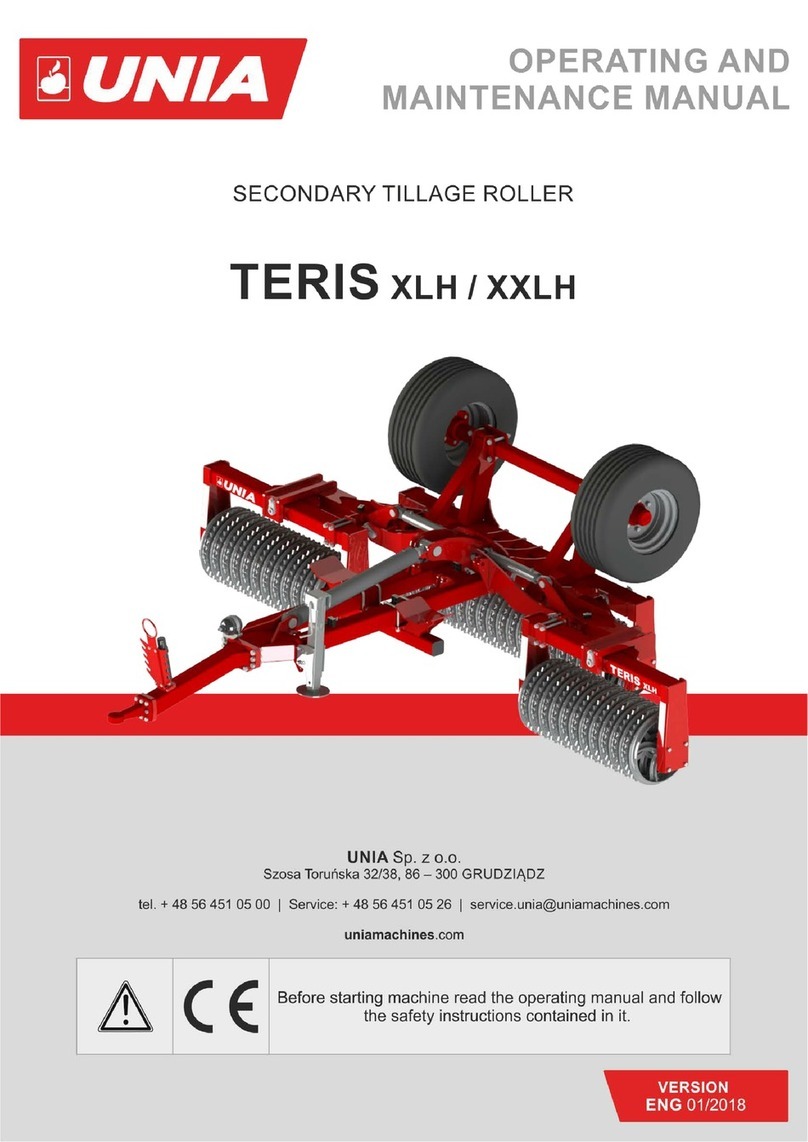
UNIA TERIS XL H Series Operating and maintenance manual
