Micron Micromax User manual

Instruction manual
Bromyard Industrial Estate, Bromyard,
Herefordshire, HR7 4HS, UK
Tel: + 44 ( ) 1885 482397
Fax: + 44 ( ) 1885 483 43
E-mail: enq[email protected].uk
URL: http://www.micron.co.uk


3
CONTENTS
This manual contains all the information required to ensure successful and
safe application of agrochemicals using sprayers fitted with one or more
MICROMAX atomisers. It should be treated as an integral part of the
machine and made easily a ailable to the spray operator for reference, as
required, during the spraying operation.
Full instructions for the efficient, effecti e and safe operation of
MICROMAX atomisers are included in this olume, along with all
necessary information for installation, maintenance and repair. Reference
may also be required to the spray ehicle and/or base sprayer handbooks.
MICROMAX CONTENTS
THE SPECIFICATIONS QUOTED ARE CORRECT AT THE TIME OF GOING TO PRINT.
THE RIGHT IS RESERVED TO VARY SPECIFICATIONS WITHOUT NOTICE.
DUE CARE HAS BEEN TAKEN IN THE PREPARATION OF THIS MANUAL. NO
LIABILITY, ABOVE THAT REQUIRED BY APPLICABLE LAWS, WILL BE ACCEPTED
FOR INJURY, LOSS OR DAMAGE DUE TO OMISSIONS OR MISTAKES.
REPRODUCTION OF THIS MANUAL, IN PART OR IN WHOLE, IS ONLY PERMITTED
WITH PRIOR WRITTEN CONSENT.
© MICRON SPRAYERS LIMITED 2002 – ALL RIGHTS RESERVED
SECTION PAGE
1Description.........................................................................4
2 Specification.......................................................................5
3 Ten key points for users......................................................6
4 Safety and the en ironment ...............................................7
5 Installation..........................................................................8
6 Basics of Controlled Droplet Application (CDA)................24
7 Calibration and adjustment ..............................................34
8 Operation.........................................................................48
9 Maintenance ....................................................................55
10 Trouble shooting ..............................................................59
11 Parts list and diagram.......................................................60
12 Notes on units and useful con ersions ..............................62
13 EC Declaration of Incorporation.......................................63
14 User notes ........................................................................64

4
1 – DESCRIPTION
ROTARY ATOMISER FOR VEHICLE MOUNTED SPRAYING
The ehicle-mounted MICROMAX is a spinning disc rotary atomiser
designed for the Controlled Droplet Application (see section 6 ‘Basics of
Controlled Droplet Application’) of most agrochemicals. By efficiently
producing only the spray droplet sizes appropriate for the particular
application the MICROMAX cuts spray olumes and costs and minimises
any risk of en ironmental contamination.
The unique design of the electrically dri en MICROMAX ensures
controlled spray atomisation o er a wide range of liquid feed rates and
gi es a choice of three disc rotational speeds, and thus spray droplet sizes,
to suit different applications:
200 μm to 500 μm spray droplets for pre-emergent and post-emergent
herbicide applications where drift a oidance is essential.
100 μm to 300 μm spray droplets for most post-emergent herbicides,
defoliants, foliar feeds and fungicides to ensure good co erage of plant
surfaces while minimising any risk of uncontrolled spray drift.
75μm to 150μm spray droplets for insecticides and fungicides.
The MICROMAX is designed primarily for use in agriculture, the materials
used in its construction will withstand all standard products used for
con entional agricultural spraying. The MICROMAX can be used with
both water and oil based sprays, but is not designed for use with liquid
fertilisers or unusually aggressi e, dense, or iscous products.
The low application olumes allowed by the MICROMAX mean greater
areas can be sprayed per tank load (or lighter ehicles used), with
dramatic sa ings in the cost, time and effort of the spraying operation.
This both speeds up the spraying process and allows more spraying days,
thus allowing quick and cost-effecti e pesticide application to be
undertaken when needed.
The MICROMAX is dri en by a 12 DC electric motor, allowing it to be
powered by the ehicle's electrical system. Disc rotational speed, and
therefore droplet size, is selected using the three gear belt and pulley dri e
system. Standard plumbing can be used.
1 – DESCRIPTION MICROMAX

5
2 – SPECIFICATION
Figure 1 – MICROMAX S ray Head
Table A – Ty ical Performance Data
Height 230 mm
(9 inches)
Disc
Diameter
125 mm
(5 inches)
Weight 1 kg
(2.2 pounds)
Power
Su ly 12 DC
Current
Drawn3A max
Power
Used 36W max
MOUNTING
BRACKET
LIQUID
FEED
NOZZLES
MOTOR
BELT AND
PULLEY DRIVE
ATOMISER
DISC
Low Medium High
Feed Rate 0.5 - 3 l/min
1 - 6.5 US pt/min
0.25 - 1 l/min
0.5 - 2 US pt/min
0.125 - 0.5 l/min
0.25 - 1 US pt/min
Disc S eed 2000 rpm 3500 rpm 5000 rpm
A lication
Volume
30 - 200 l/ha
3 - 21 US gpa
20 - 80 l/ha
2 - 8.5 US gpa
10 - 40 l/ha
1 - 4 US gpa
Dro let Size 200 - 500 μm 100 - 300 μm 75 – 150 μm
S eed Setting
MICROMAX 2 – SPECIFICATION

6
3 – TEN KEY POINTS FOR USERS
The following list is intended to be referred to prior to commencing each
spraying operation, to remind users of the key points for the safe and
efficient use of the MICROMAX atomiser.
1SAFETY: Always refer to the product label for specific
recommendations for each product, and to Section 4 ‘Safety and
En ironmental Considerations’ before commencing any spraying
operation.
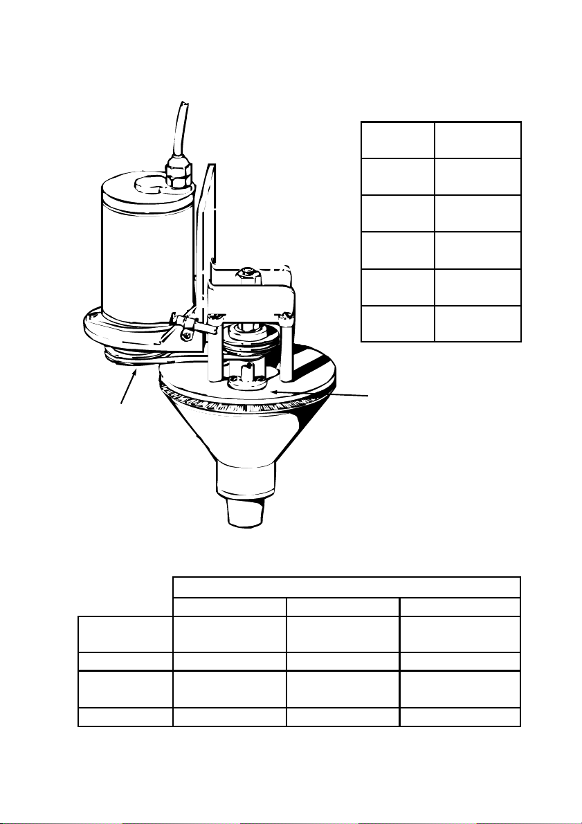
2 Check that all atomisers rotate freely. If binding or roughness is felt,
inspect the motor, belt dri e and disc bearings.
3 Check that the pulleys and belts are clean and free from damage
and that the appropriate gear is selected, see Section 7 ’Calibration
and Adjustment’.
4 Check that the atomiser discs are secure and free from damage or
blockage by dried chemical.
5 Ensure that the atomisers are securely and correctly positioned on
the boom or support structure, and are set to the correct distance
from the crop/target to be sprayed, see Section 5 ‘Installation’.
6 Inspect the entire sprayer for damaged or twisted hoses, leaks in the
chemical system, or damaged wires.
7 Check that the correct nozzles and flow restrictor orifices are fitted,
and that the correct system pressure is set to pro ide the required
liquid feed rate, see Section 7 ‘Calibration and Adjustment’.
8 Turn the atomiser motors on, to ensure they are rotating and at the
correct speed, see Section 7 ‘ Calibration and Adjustment’.
9 Whilst spraying, isually ensure that each atomiser is working, and
erify the accuracy of the calibration of the sprayer by checking the
olume of liquid used against the area being sprayed.
10 After use, always flush out the entire system with clean water or a
suitable sol ent. Never lea e chemical residues in the tank or pipe
work. Wash off outer surfaces of atomisers, booms, etc. to a oid
build up of pesticide residues.
3 – TEN KEY POINTS FOR USERS MICROMAX

7
4 – SAFETY AND THE ENVIRONMENT
Using agrochemicals is a hazardous process. Operators should be
familiar, and comply, with all rele ant legislation and/or regulations.
Keep people and animals out of areas being sprayed. Obser e all
regulations on spraying near inhabited or public areas and waterways.
Never use MICROMAXs in potentially explosi e atmospheres, or spray
flammable liquids, mixtures of incompatible chemicals, suspended
insoluble particles, or anything other than agrochemicals through them.
Always read the product label carefully to disco er:
recommended application rate and dilution
operator protection required
necessary en ironmental protection measures
action required in case of accidental spill,
ingestion, skin or eye contact
Never eat, drink, or smoke when working with agrochemicals.
Always store agrochemicals safely to protect people and animals, and to
safeguard the en ironment. Wash and rinse chemical product containers
well using proper equipment. Make a hole in the bottom of empty
containers to pre ent re-use. Dispose of containers, unused
agrochemicals, and washing residues in accordance with regulations.
4.1 OPERATOR PROTECTION
Always wear the protecti e clothing items listed on the product label for
mixing and filling. After using agrochemicals or handling equipment
always wash your hands and clothes thoroughly.
The minimum protecti e clothing required for spraying with the
MICROMAX from an uncabbed ehicle, or of cleaning contaminated
atomisers and sprayers is:
rubber glo es
boots/shoes & long trousers
eye protection
long slee ed shirt
MICROMAX 4 – SAFETY AND THE ENVIRONMENT

8
5 – INSTALLATION
The design of a sprayer incorporating one or more MICROMAX atomisers
will ary according to the crop or target to be sprayed.
This section gi es general ad ice and design data but is not intended to
pro ide specific instructions for building e ery type of sprayer. Original
Equipment Manufacturers (OEMs) should contact Micron if they require
any further information for a particular application.
Figure 2 – A boom s rayer for field cro s
5.1 MOUNTING THE MICROMAX
5.1.1 Some ty ical configurations
The design of agricultural equipment is best done by a qualified
and com etent engineer. All rele ant legislation and
regulations should be adhered to.
Agricultural equipment should only be worked on by suitably
trained ersonnel. Manufacture and assembly work should
be completed by trained and com etent technicians.
Ensure that all welds are sound, and that all fasteners used are
correctly tightened.
Use the correct tools for the job to a oid injury or damage.
Use safe lifting methods when mo ing hea y components.
IMPORTANT SAFETY RECOMMENDATIONS
!
5 – INSTALLATION MICROMAX

9
Figure 3 – A boom s rayer for orchard floors
Figure 4 – An ATV s rayer for orchard floors, grassland, etc.
5.1.2 Strength and rigidity
Support arms or frameworks should be of strong and rigid construction.
Spray booms should also be rigid, and preferably pro ided with
suspension. If the boom is lightweight in construction, it is ad isable to
reinforce and stabilise it.
Excessi e bouncing will cause une en spray output from the MICROMAX.
Brace bars, nylon support ropes and springs are common methods of
reducing boom bounce.
5.1.3 Folding booms
If mounting MICROMAX atomisers on a folding boom, it is essential to
ensure that the atomisers are positioned such that they do not interfere
with the folding mechanism.
MICROMAX 5 – INSTALLATION

10
If mounting MICROMAXs on a spray boom, one or more extension arms
may be required to pro ide the necessary clearance from the sprayer,
support wheels, or other obstructions. These arms can be constructed
from hea y gauge 40 mm (1.5 inch) or larger angle iron, channel, tube or
box section. They should be constructed and mounted so as to be as rigid
as practicable, to minimise bounce.
5.1.4 S ray attern clearance
The MICROMAX produces a large hollow cone spray pattern, arying in
diameter with different atomiser speeds/droplet sizes. Support arms or
frameworks should be designed to allow a radial clearance of 1.2m (4
feet) to pre ent spray pattern disruption.
Figure 5 – S ray attern clearance
Figure 6 – S rayer clearance
EXTENSION ARMS
MICROMAXSPRAY PATTERN
BOOM
1.2m (4 feet)
CLEARANCE RADIUS
5 – INSTALLATION MICROMAX

11
TYPICAL STEEL BOX
SECTION BOOM
CLAMPS
EXTENSION ARM
Figure 7 – Extension arm
Figure 8 – Distance above target
A height of 0.5m (20 inches)
abo e the top of the crop
canopy or target is
recommended (measured
from the atomiser disc’s
lowermost teeth). This can
be lowered if drift reduction
is a priority.
5.1.5 Distance from cro or target
5.1.6 Boom end su orts
If using a boom sprayer, it is ad isable to fit boom tip wheels or skids to
protect the end MICROMAX atomisers from contact with the ground.
0.5m (20 inches)
DIRECTION
OF TRAVEL
MICROMAX 5 – INSTALLATION

12
5.1.7 S acing of multi le atomisers
The most ideal spacing between MICROMAX atomisers, for multi-purpose
use, is 1m (40 inches).
At the lowest atomiser speed a wider spacing is possible and has been
successfully used. O erlap of spray pattern can be expected up to 2m (80
inches) under calm conditions e.g. for spraying orchard floors.
Figure 9 – S acing between atomisers
Figure 10 –
Mounting angle
5.1.8 Angle of atomisers
The MICROMAX is mounted utilising the
integral ertical ‘bolt plate’ and suitable bolts. A
secondary bracket is a ailable separately gi ing
a 15˚ angle for post-emergent crop spraying.
It is recommended that the MICROMAX is fitted
ertically for applying pre-emergent/pre-plant
herbicides. This is also strongly recommended
for spraying herbicides in orchards (to reduce
the possibility of chemical injury to trees).
An angle of 15˚ is recommended as a good
general purpose position for most post-emergent
herbicide, insecticide, fungicide, defoliant, and
desiccant applications to help impro e canopy
penetration.
PATTERN OVERLAP SPRAY PATTERN
CENTRED ON
ATOMISER
1m (20 inches)1m (20 inches)
VERTICAL
15˚
DIRECTION
OF TRAVEL
5 – INSTALLATION MICROMAX

13
5.2 LIQUID FEED SYSTEM
The design of the liquid feed system will depend on the number of
MICROMAX atomisers to be used, the design of the sprayer, and whether
the sprayer is newly built or a modified older sprayer.
Many of the components for the liquid feed system are a ailable direct
from Micron, otherwise contact your usual sprayer component supplier.
5.2.1 Flow regulation
The flow of spray liquid to each MICROMAX atomiser must be regulated
to gi e the correct total output from the sprayer and consequently the
required olume application rate on the crop or target. See Section 7
‘Calibration and adjustment’ for olume application rate calculations.
The liquid feed rate is regulated by the MICROMAX’s coloured nozzles, or
a combination of nozzles and either a fixed restrictor or a Variable
Restrictor Unit (VRU) in the feed pipe to each atomiser. The most
common configuration is to use the coloured nozzles and a fixed ‘orifice
plate holder’ unit. The restrictor unit should be placed in the spray line
just before the MICROMAX atomiser, after any filters and the Diaphragm
Check Val e (DCV). See Figure 11 ‘Typical spray liquid feed system’ on
page 14.
The appropriate nozzles and VRU setting or orifice plate that gi e a feed
rate, at the nominal system pressure, nearest to that required for the
application are selected. Fine adjustment of feed rate is then achie ed by
arying spray line pressure. See Section 7 ‘Calibration and adjustment’
for details on using system pressure and nozzle and orifice selection to set
the required olume application rate.
Unlike hydraulic nozzles, MICROMAX atomisers do not require pressure
to operate and droplet size is unaffected by the system pressure. The
pressure is therefore only selected to gi e the correct liquid flow.
5.2.2 Dia hragm Check Valves (DCVs)
It is strongly recommended that a suitable Diaphragm Check Val e (DCV)
be fitted in the spray liquid line to each MICROMAX, just before the flow
restrictor (see Figure 11 ‘Typical spray liquid feed system’ on page 14).
This will ensure that spray liquid does not escape from the system once
the spray al e is shut off, minimising the risk of off target spraying.
MICROMAX 5 – INSTALLATION

14
5.2.3 Filtration
A filter must be incorporated in the spray liquid supply. This should ha e
a 0.5 mm (50 mesh/inch) or finer mesh filter.
The filter may be installed either in the suction or pressure line of the
pump, but the filter must always be before any flow restrictors and should
preferably be before the pressure regulator. It is most common to fit the
filter to the suction line of the pump to protect the pump itself (see Figure
11 ‘Typical spray liquid feed system’ on page 14).
Secondary filtration is strongly recommended to catch any smaller
particles missed by the main filter, as well as any particles that may
already be present in the spray lines, or rust particles etc.
Secondary filters (i.e. nozzle filters) should be fitted just before the DCV
and flow restrictor for each MICROMAX atomiser. A finer mesh 0.25 mm
(100 mesh/inch) filter is recommended.
The main purpose of filtration in a MICROMAX system is to protect the
pump and al es, and to pre ent partial or total blockage of the flow
restrictors. The MICROMAX is itself ery difficult to block, due to the
nature of the rotary disc atomiser.
5.2.4 Pum s
If a new sprayer is being designed or an original pump is to be replaced, it
is recommended that a diaphragm or centrifugal type is chosen. This
should be able to pro ide a pressure of about 3 bar (45 psi), and should
be capable of deli ering the maximum flow rate required of the sprayer
plus the flow required for tank agitation (if a mechanical agitator is not
used).
Each MICROMAX atomiser takes a maximum of 3 l/min (6.5 US pt/min).
Consult the specifications of your base sprayer (or tank manufacturer) for
the required flow for tank agitation.
5.2.5 Materials
All liquid feed system components should be rated for the system pressure
to be used, and manufactured from materials that will not be degraded by
weathering or agrochemicals. It is best to source components from Micron
or other specialist agricultural sprayer component suppliers.
5 – INSTALLATION MICROMAX

15
5.2.6 On/Off valve
An on/off al e must be fitted in the main liquid feed to the MICROMAX
atomiser/s (see Figure 11 ‘Typical spray liquid feed system’ on page 14).
This may be mechanically or solenoid operated, but should be positioned
so as to be easily and safely actuated by the sprayer operator whilst
dri ing the sprayer.
Se eral on/off al es plumbed in parallel, or a multi-position al e, can be
used to select different groups of MICROMAX atomisers if required (for
example for multiple boom sections).
5.2.7 Pi e and hose sizes
The bore size of the components and the pipes or hoses required will
depend on the number of MICROMAX atomisers connected to the
system, and therefore the maximum flow required at the operating
pressure. The use of rigid pipe or flexible hose is purely at the designer’s
discretion.
For pump connection, the pump manufacturer’s guidelines should be
followed. Howe er, 20 mm (0.75 inch) bore hose on the suction side and
13 mm (0.5 inch) bore hose on the pressure side are recommended as a
minimum for one atomiser systems. For systems with multiple atomisers,
hose bore sizes up to 40 mm (1.5 inch) on the pump’s suction side and 32
mm (1.25 inch) on the pressure side may be required.
All hoses, pipes, and components upstream of the pump should be the
same bore size as the pump’s suction side hose.
All hoses, pipes, and components downstream of the pump, up to the on/
off al e (or al es), should be the same bore size as the pump’s pressure
side hose (including the bypass return line).
If only one MICROMAX is connected to the on/off al e, it is
recommended that 13 mm (0.5 inch) bore hose or pipe is used to connect
up to the nozzle filter. The bore size should then be reduced to 6mm
(0.25 inch) for the remaining downstream components and connections.
For systems where more than one MICROMAX is connected to the on/off
al e, it is recommended that the pump pressure side hose bore size is
continued up to the split. The bore size should then be reduced to 13 mm
(0.5 inch), and connection continued as for the single atomiser system
described abo e.
MICROMAX 5 – INSTALLATION

16
Figure 11 – Ty ical s ray liquid feed system
0.5 mm (50 MESH/INCH) MESH FILTER
3 WAY LEVER OPERATED ISOLATING / CHANGEOVER VALVE
DIAPHRAGM OR CENTRIFUGAL PUMP
3 BAR (45 PSI) OUTPUT AT REQUIRED FLOW RATE
ADJUSTABLE SINGLE STAGE PRESSURE REDUCING VALVE
12v DC SOLENOID OPERATED TWO POSITION ON/OFF VALVE
POWER SUPPLIED BY SPRAYER’S ELECTRICAL SYSTEM
OPERATED BY SWITCH IN SPRAYER’S CAB OR NEAR TO DRIVER
0.25 mm (100 MESH/INCH) MESH IN-LINE FILTER
LOW PRESSURE DIAPHRAGM CHECK VALVE (DCV)
ORIFICE PLATE HOLDER TYPE FIXED FLOW RESTRICTOR UNIT
6mm (0.25 INCH) BORE HOSE CONNECTION
SPLIT USING 6mm (0.25 INCH) BARB ‘Y’ PIECE
CONNECTED TO 2 FEED NOZZLES ON MICROMAX TOP PLATE
a
b
c
d
e
f
g
h
i
NOTES:
5 – INSTALLATION MICROMAX
SPRAY LIQUID TANK
FLUSH
TANK
AGITATOR
SERVICE
VALVE (b)
REGULATOR
VALVE (d)
MULTIPLE MICROMAXs IN A SECTION
ON/OFF VALVES FOR
MULTIPLE SECTIONS
PUMP (c)
SUCTION
FILTER (a)
(a) -(i)

17
5.2.8 Flow indicators
It may be desirable to fit flow indicators in the feed lines to each
MICROMAX atomiser. The flow indicators should be positioned so as to
be clearly isible to the spray operator whilst dri ing the sprayer, without
the operator needing to take their eyes off the direction of tra el for more
than a few seconds. Larger numbers of MICROMAX atomisers may be
monitored in groups (such as boom sections) in order to reduce the
number of indicators required and the complexity of the plumbing.
5.2.9 Modification of an existing system
Before working on an existing liquid feed system, always flush
out the entire system with clean water or a suitable sol ent and
wash off outer surfaces.
When working on a sprayer that has been used with
agrochemicals, always treat it as contaminated, e en if it has
been thoroughly flushed and cleaned. Refer to Section 4
‘Safety and the en ironment’ for recommended precautions.
Legislation and regulations on the design of sprayers ha e
changed significantly o er the last few decades. Older sprayers
should be upgraded to meet the latest requirements. If this is
not practicable they should be replaced.
IMPORTANT SAFETY RECOMMENDATIONS
!
If an older sprayer is being modified, it is essential that the spray liquid
feed system is thoroughly cleaned and o erhauled. Any rusty or damaged
pipes or hoses should be replaced, al es should be checked for correct
operation, the pump should be ser iced, and the filters cleaned or
replaced.
The original spray pump can normally be retained. If this pump is a high
pressure type or if it has excess capacity, it may be necessary to fit an
adjustable pressure regulator in the liquid supply line to the atomisers. If a
pressure regulator is already fitted but cannot be adjusted to a sufficiently
low pressure, it will be necessary to either fit a second low pressure
regulator to the output of the main regulator, or to replace it.
MICROMAX 5 – INSTALLATION

18
Failure to follow the recommendations in this section, and good
electrical wiring practice, may lead to serious damage to the
MICROMAX’s motor. Unsafe conditions may also arise, such
as; excessi e heating of components, risk of fire, and damage to
the spray ehicle’s safety critical systems.
It is strongly recommended that the electrical system be
designed and installed by a qualified and com etent
electrician with reference to the ehicle manufacturer’s
recommendations.
IMPORTANT SAFETY RECOMMENDATIONS
!
5 – INSTALLATION MICROMAX
When retro-fitting multiple MICROMAX atomisers to a boom sprayer it is
common to utilise most of the existing spray system. MICROMAXs are
generally plumbed to e ery other existing nozzle holder, the holders in
between being blanked off, if nozzles are spaced at 0.5m (10 inches).
The usual arrangement is to fit a suitable DCV unit and nozzle filter into
the nozzle holder. A nozzle cap, usually one for disc and core type hollow
cone nozzles, is then fitted with a 6 mm (0.25 inch) hose barb adapter.
This is fitted to the DCV unit in place of the con entional nozzle and cap,
allowing connection of 6 mm (0.25 inch) bore hose. The MICROMAX
plumbing is then continued as per Figure 11 ‘Typical spray liquid feed
system’ on page 14.
Some DCV units allow an orifice plate to be fitted before the nozzle cap
and hose barb, otherwise a separate orifice plate holder should be fitted in
the line to the atomiser, before the split to feed the two nozzles.
The components required for attaching to most common nozzle holders
can be obtained from Micron, otherwise contact your usual spray
component supplier.
5.3 ELECTRICAL SYSTEM
The design of the electrical system will depend on the number of
MICROMAX atomisers to be used and the a ailable electrical power. This
section pro ides general ad ice and design data for use by a technically
competent person.

19
All components needed to build the electrical system should be a ailable
from your usual specialist electrical component supplier, otherwise contact
Micron for ad ice.
5.3.1 Motor rating
The MICROMAX is dri en by a permanent magnet DC motor.
6000 rpm (achie ed at approximately 14 DC) and 3A are the maximum
recommended speed and current ratings.
5.3.2 Voltage vs. s eed, current vs. flow
The MICROMAX motor’s rotational speed is almost directly proportional
to the oltage applied across it. Correct disc speed is essential to ensure
appropriate spray quality (see section 6 – ‘Basics of Controlled Droplet
Application’). It is essential to ensure, therefore, that the oltage across
the motor is as near to 12 DC as is practicable (max. +/- 1 DC).
The current drawn by the MICROMAX’s motor will increase as the flow
rate of chemical liquid is increased. Higher flow rates than the maximums
quoted in Table A ‘Typical Performance Data’ on Page 3 should not be
used. This risks o erloading and damaging the MICROMAX’s motor, and
will also cause a deterioration in the droplet size spectrum.
5.3.3 Switch Box
A master on/off switch and ‘power on’ indicator should be fitted in order
to be able to turn the MICROMAX atomiser/s on and off as required. The
switch should be large and easily operated with a glo ed hand, yet
difficult to accidentally actuate (i.e. when dri ing the sprayer). The
indicator should be bright enough to be isible in all daylight conditions.
If more than one atomiser is to be controlled high power components
should be used, since each MICROMAX can use up to 36 watts and draw
up to 3A. It is common for multi-atomiser systems, such as boom
sprayers, to use a high power relay to effect switching, with the actual
switch operating the relay actuation circuit.
The switch (and relay if used) and indicator should be mounted in a
suitable weatherproof enclosure, which shall be referred to as the ‘switch
box’ in the following sections.
MICROMAX 5 – INSTALLATION

20
5.3.4 Location of the switch box
The switch box should be securely mounted, and located so as to
minimise the length of the battery leads and the MICROMAX power
cables. Care should be taken to position the switch box so that it causes
no impediment to the safe operation of the sprayer.
It is desirable that the sprayer operator, whilst in the dri ing position,
should be able to comfortably and safely operate the switch. This is not,
howe er, essential if it is impractical. The spray liquid on/off al es are
the primary method of turning the sprayer on and off whilst in operation
(i.e. when turning at the end of rows).
5.3.5 Power su ly
In most instances the MICROMAX’s electrical system will be connected to
the spray ehicle’s system, powered by the alternator. It is recommended
that connection is made directly to the ehicle’s battery terminals (see
Figure 12 ‘Typical electrical system’ on page 21).
It is essential to check the spray ehicle manufacturer’s specifications to
ensure that the alternator has sufficient spare capacity to dri e the
required number of MICROMAXs. If not, a larger alternator or dedicated
electrical supply must be fitted.
A dedicated electrical supply may be preferred or needed, such as a PTO
shaft dri en generator. In this case it is recommended that the dedicated
supply be used to charge a large capacity hea y duty battery. The
MICROMAX electrical system should then be connected to the battery,
which will act as a buffer or accumulator to smooth the supply.
5.3.6 Fuses and circuit rotection
The ehicle’s electrical system should be protected by fitting a master fuse
into the positi e battery lead. This should be located as near as possible
to the battery terminal connection (see Figure 12 ‘Typical electrical
system’ on page 21).
The master fuse should be a ‘slow blow’ automoti e type. Some
experimentation may be required to obtain the best balance between
circuit protection and the a oidance of nuisance blowing. As a guide,
allow 3A per MICROMAX then add 10%. A circuit breaker may be used,
if preferred, instead of a fuse.
5 – INSTALLATION MICROMAX
Table of contents
Popular Farm Equipment manuals by other brands

Flory
Flory 860 Operator's manual

Multiva
Multiva Avaran 500 Operation and maintenance manual

Bush Hog
Bush Hog CBH60 Operator's manual

Checchi & Magli
Checchi & Magli BABY TRIUM Use and maintenance manual

Michel's
Michel's CROP CATCHER 3 instruction manual

EASY COOPS
EASY COOPS Chicken Coop Plan 4x6 Assembly instructions

WIL-RICH
WIL-RICH SoilPro 513 Assembly instructions

Omlet
Omlet Zippi mesh pet run instruction manual

Widu-Mühlenbau
Widu-Mühlenbau Volks Mill Mod. II Operation manual

New Holland
New Holland 330GM Operator's manual

Fullwood
Fullwood Revolution II Stage 3 Installation instruction

EASY COOPS
EASY COOPS 5x6 Chicken Coop Plan Assembly instructions