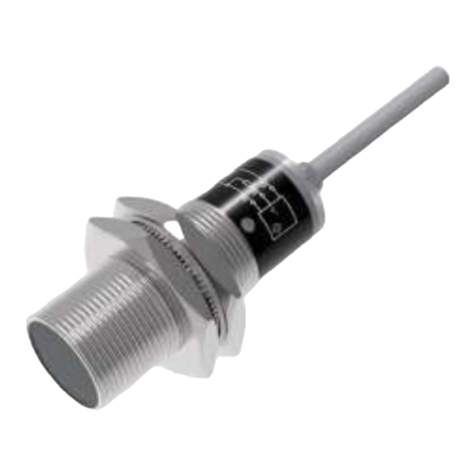
Infinite L-com SRWQ100-pH104-8701 User manual

1
pH SENSOR (WATER QUALITY ANALYSIS)
User Manual for SRWQ100-pH104-8701
Thank you for choosing L-com product. To ensure safe, accurate performance and product
longevity, please take a moment to familiarize yourself with this manual before powering the
device. Please keep it handy for future reference. In case of any questions regarding the
installation or use of product, please call us at 800.341.5266.
Reach out to us at customerservice@l-com.com and visit our website at www.l-com.com
M_SRWQ100-pH104-8701_05/2022_R1.0
Signal Line

2
Technical Data
Instructions Before Use
Electrode bulb is fragile and cannot be repaired after damage.
During measurement process, if there is dirt, adhesive or scale on the electrode bulb, the
measured value will be inaccurate or fluctuate. It should be cleaned and calibrated from
time to time.
If there is bubble in the bulb, the measured value will be inaccurate or fluctuate. User can
gently shake the electrode bulb to remove the bubble.
Electrode Wiring
Please follow the instructions carefully, wrong wiring will damage the product completely.
Examine all the wiring carefully in the system. Make sure wiring is complete before
switching ON the power.
It is strictly forbidden that RS485A line and RS485B line should not touch the power line.
It will permanently damage the communication of the electrode.
pH Range 0 14 pH
Resolution 0.01 pH
Accuracy ±0.01 pH
pH Balance 7.00 ± 0.25
Temperature Range 0 60.0 ˚C
Resolution 0.1 ˚C
Accuracy ±0.3 ˚C
Temperature Compensation Automatic
Slope ≥96%
Output RS485, 4 20 mA
Power Supply 9 30 VDC (Recommend 12V)
Pressure Range 0
Shell Material PPS, ABS
Liquid Junction PTFE
Pipe Thread M 39*1.5
Cable Length 5m or customized
Protection Grade IP68

3
Electrode Activation
The electrode should be activated in 3 M KCL solution.
Dry electrode must be activated before use.
Electrode Calibration
The electrode has been calibrated before shipment, user can directly use it.
It is recommended to use the two-point method for calibration, usually with 6.86pH or
7.00 buffer solution to calibrate the zero point. Then the slope is determined with the
buffer solution of 4.01pH or 9.18.
The electrode should be calibrated in fresh buffer solution. If the solution to be tested is
acidic, the pH of the buffer solution should be less than the solution to be tested. If the
solution to be tested is alkaline, the pH of the buffer solution should be greater than the
solution to be tested.
Users are recommended to calibrate the electrode every 1 to 2 months.
Put the electrode into the buffer solution of pH4.01 and
soak for 10 mins, and then soak in buffer solution of pH
6.86 for 10 mins.
Rinse the electrode with distilled water or deionized
water and dry it with a paper towel.
Electrode Outlet

4
Put the electrode in pH 6.86 or 7.00 buffer solution and
wait until the value is stable, calibrate the first point .
Then take the electrode out of the buffer solution, rinse
and dry it with a paper towel.
Put the electrode in pH 4.01 or 9.18 buffer solution and
wait until the value is stable, calibrate the second
point .Then take the electrode out of the buffer solution
rinse and dry it with a paper towel.
Electrode Installation
It is recommended pH electrode to be installed in the flow cell for more stable and
accurate measurement.
If electrode is installed in the pipe, the right angle should be 15°~165°.
Follow the procedure below:

5
During Immersion Installation
During installation procedure, there will be frequent dirt on electrode, clean it regularly.
Measuring value is not stable.
Different insertion depths affects the measured value.
The position of the electrode must be above the sediment.
Electrode Communication
Default Communication Instructions:
Data starting at 0x represents hexadecimal.
The check code is 16CRC, the low byte is in the front and the high byte is in the back.
Floating point number occupy four bytes.
Communication Description (Factory Default):
Host Computer Transmission Format:
Function Code Description:
This product supports 03,06,16 and other common function codes.
The output register uses 16 function codes when writing double word data or writing
multiple data in batches.
Baud Rate 9600 (Default)
Data Bit 8
Stop Bit 1
Check Bit No
Address 1 (Default)
Data Type Description Remarks
Integer 16-Bit
Integer
The high-low bytes of word
component are not reversed
Ex: O x 0032 to decimal
number is 50
Floating
Point
Number
(CDAB)
3412
The high-low word of the
double-byte component is
reversed, but the high-low
byte of the word is not
reversed.
Example: 72 37 41 DB transfer to
floating point number.
CDAB change order is ABCD.
Eg: 41 DB 72 37 transfer to floating
point is 27.4
03 Read single or multiple registers
06 Write single register
16 Write multiple registers

6
ID
Address
Func-
tion
Code
Register Start
Address
Qty. Of
Registers
CRC16
High
Byte
Low
Byte
High
Byte
Low
Byte
High
Byte
Low
Byte
Eg: Read
Measured
Value
0x01 0x03 0x00 0x01 0x00 0x02 0xCB 0x95
Eg: Read
Temp. Value
0x01 0x03 0x00 0x03 0x00 0x02 0x0B 0x34
ID
Address
Func-
tion
Code
Qty of
Registers
CRC16 Read Register Data in
Hexadecimal Floating Point
Number
CDABHigh
Byte
Low
Byte
Eg:
Measured
Value
Return
0x01 0x03 0x04 0x2C 0x81 0x40 0x91 0xE7 0x52
Eg: Temp.
Value
Return
0x01 0x03 0x04 0x72 0x37 0x41 0xDB 0x8E 0x20
Slave Computer Response Format:
Note: 72 37 41 DB transfer to floating point number, CDAB change order is ABCD,
i.e. 41 DB 72 37 transfer to floating point is 27.4.
Read Integer
Host Computer Transmission Format:
Slave Computer Response Format:
ID
Address
Function
Code
Register Start
Address
Qty. Of
Registers
CRC16
High
Byte
Low Byte High
Byte
Low
Byte
High
Byte
Low
Byte
Eg: Read
Warning
Status
0x01 0x03 0x00 0x07 0x00 0x01 0xCB 0x35
ID
Address
Function
Code
Qty of
Registers
Read Register Data in
Hexadecimal Floating
Point Number
CRC16
ABHigh
Byte
Low
Byte
Eg: Measured
Value Return
0x01 0x03 0x02 0x00 0x00 0x44 0xB8
Read Floating Point Number
Host Computer Transmission Format:

7
ID Func-
tion
Code
Register
Start
Address
Qty. Of
Registers
Qty
Of
Byte
CRC16 Register Data in
Hexadecimal Floating
Point Number
High
Byte
Low
Byte
High
Byte
Low
Byte
CDABHigh
Byte
Low
Byte
Eg:
Write
Value
Offset
0x01 0x10 0x00 0x12 0x00 0x02 0x04 0x
00
0x
00
0x
3F
0x
80
0x2A 0x63
Write Floating Point Number
Host Computer Transmission Format:
Slave Computer Response Format:
Note: The measured value if offset by 1.00, floating point number 1.00 coverts to
hexadecimal 0X3F800000, transpose the high and low positions 0X00003F80 and write
0X0012.
Write Integer
Host Computer Transmission Format:
Slave Computer Response Format:
Note: Change the local computer address 1 to address 2 and write the hexadecimal
number 0X00 02 into register 0X00 19.
ID
Address
Function
Code
Register Start
Address
Qty. Of
Registers
CRC16
High
Byte
Low
Byte
High
Byte
Low
Byte
High
Byte
Low
Byte
Eg: Return
Value Offset
0x01 0x10 0x00 0x12 0x00 0x02 0xCD 0xE1
ID
Ad-
dress
Func-
tion
Code
Register Start
Address
Register Data in
Hexadecimal Integer
CRC16
High
Byte
Low
Byte
ABHigh
Byte
Low
Byte
Eg: Write
Device
Address
0x01 0x06 0x00 0x19 0x00 0x02 0xCC 0xD9
ID
Ad-
dress
Func-
tion
Code
Register Start
Address
Register Data in
Hexadecimal Integer
CRC16
High
Byte
Low
Byte
ABHigh
Byte
Low
Byte
Eg: Device
Return
Address
0x01 0x06 0x00 0x19 0x00 0x02 0xCC 0xD9

8
Name Hosting
Number
Data
Type
Length Read/
Write
Description
Measurements 0x 00 01 Floating
Point 2Read Storage location for measured
value
Temperature
measurement 0x 00 03 Floating
Point 2Read Storage location for measured
temperature
Current output
value 0x 00 05 Floating
Point 2Read Output current based on
PH/ORP measurements
Warning 0x 00 07 Integer 1Read
00: Normal
01: Measurement exceeds the
upper limit
02: Measurement exceeds the
lower limit
03: Temperature exceeds the
upper limit
04: Temperature exceeds the
lower limit
Measure mode 0x 00 08 Integer 1Read/
Write 00: pH ; 01: ORP
Address Description
Calibration Instructions
Before Calibration:
Write the value of zero calibration (i.e., the value of the first point) and the value of
slope calibration (i.e., the value of the second point) to the electrode before calibration.
If the zero calibration value is 6.86pH, write the data 0x01to register 0x36.
Send command: 01 06 00 36 00 01 A8 04.
If the slope calibration value is 4.01pH, write the data 0x01 to register 0x38.
Send command: 01 06 00 38 00 01 C9 C7.
Start Calibration:
First Step:
Clean and dry the electrode. Put the electrode in the solution 6.86 of zero point
calibration. Send command: 01 03 00 66 00 01 64 15.
After the measured ADC value is stable, read the ADC value in the 0x66 register.
Write the instruction to confirm the calibration to the 0x3E register.
Send command: 01 06 00 3E 00 FF A8 46.
Second Step:
Clean and dry the electrode ,put the electrode in the solution 4.01 of slope calibration.
Send command: 01 03 00 66 00 01 64 15.
After the measured ADC value is stable, read the ADC value in the 0x66 register.
Write the instruction to confirm the calibration to the 0x3F register.
Send command: 01 06 00 3F 00 FF F9 86.

9
Name Hosting
Number
Data
Type Length Read/
Write Description
Upper limit of measure-
ment 0X 00 0A Floating
Point 2Read/
Write
Upper limit of measured value
(20mA corresponding value)
Lower limit of
measurement 0X 00 DC Floating
Point 2Read/
Write
Lower limit of measurement value
(4mA corresponding value)
Upper temperature limit 0X 00 OE Floating
Point 2Read/
Write Upper temperature limit
Lower temperature limit 0x 00 10 Floating
Point 2Read/
Write Lower temperature limit
Measured value offset 0x 00 12 Floating
Point 2Read/
Write Adjust measurement
Temperature offset 0x 00 14 Floating
Point 2Read/
Write Adjust temperature value
Damping
coefficient 0x 00 16 Integer 1Read/
Write 0-10
Device address 0x 00 19 Integer 1Read/
Write 1-255
Baud rate 0X 00 1A Integer
1
Read/
Write
0=2400 , 1=4800 , 2=9600
3=19200, 4=38400
Restore factory 0X 00 1B Integer 1Write
ORP calibration value 0x 00 30 Floating
Point 2Read/
Write
Calibrating slope 0x 00 34 Integer 2Read -0.1984
Zero point
calibration solution 0x 00 36 Integer 1Read/
Write 0=7.00, 1=6.86
Slope calibration solu-
tion 0x 00 38 Integer 1Read/
Write
0=1.68 , 1=4.01 , 2=9.18
3=10.1 , 4=12.45
Manual
temperature 0X 00 3A Floating
Point 2Read/
Write 25°c
Zero confirmation 0X 00 3E Integer 1Write
Slope confirmation 0X 00 3F Integer 1Write
Measured ADC 0x 00 66 Integer 1Read

10
Sr.
No. Function Send command Return command Remarks
1
Read
measured
value
01 03 00 01 00 02 95 CB 01 03 04 2C 81 40
91 52 E7
The 2C814091 change
order is 40912C81 and its
floating point is 4.53
2
Read
temperature
measurement
01 03 00 03 00 02 34 0B 01 03 04 72 37 41
DB 20 8E
The 723741DB change
order is 41DB7237and its
floating point is 27.4
3Read current
output value 01 03 00 05 00 02 D4 0A 01 03 04 00 00 41
40 CB 93
The 00004140 change
order is 41400000 and its
floating point is 12.00
4Read warning 01 03 00 07 00 01 35 CB 01 03 02 00 00 B8
44 0000 is the current state
5
Write
measurement
mode
01 06 00 08 00 01 C9 C8 01 06 00 08 00 01
C9 C8 Set to ORP mode
6
Write
upper limit of
measurement
01 10 00 0A 00 02 04 00
00 41 20 42 58
01 10 00 0A 00 02
61 CA
The upper
measurement limit is set to
10.00
7
Write lower
limit of
measurement
01 10 00 0C 00 02 04 00
00 3F 80 E3 AA
01 10 00 0C 00 02
81 CB
The lower
measurement
limit is set to 1.00
8
Write upper
temperature
limit
01 10 00 0E 00 02 04 00
00 42 C8 43 15
01 10 00 0E 00 02
20 0B
The upper
temperature limit is
set to 100.00
9
Write lower
temperature
limit
01 10 00 10 00 02 04 00
00 40 A0 C3 1B
01 10 00 10 00 02
40 0D
The lower temperature
limit is set to 5.00
10
Write
measured
value offset
01 10 00 12 00 02 04 00
00 3F 80 63 2A
01 10 00 12 00 02
E1 CD Set to 1.00
11
Write
temperature
offset
01 10 00 14 00 02 04 00
00 3F 80 E3 00
01 10 00 14 00 02
01 CC Set to 1.00
12 Write damping
coefficient 01 06 00 16 00 01 A9 CE 01 06 00 16 00 01
A9 CE Set to 1
13 Write device
address 01 06 00 19 00 02 D9 CC 01 06 00 19 00 02
D9 CC Set to 2
14 Write baud
rate 01 06 00 1A 00 00 A8 0D 01 06 00 1A 00 00
A8 0D Set to 2400
15 Write restore
default 01 06 00 1B 00 FF B9 8D 01 06 00 1B 00 FF
B9 8D
Factory default values are
restored after sent
Common Instruction Examples

11
Sr.
No. Function Send command Return command Remarks
16
Write ORP
calibration
value
01 10 00 30 00 02 04 00
00 42 AC C0 66
01 10 00 30 00 02 41
C7
Write ORP standard liquid
value 86mV
17
Read
calibration
slope
01 03 00 34 00 02 85 C5 01 03 04 CC CD 3E
4C 45 09
The CCCD3E4C change
order to 3E4CCCD and its
floating point is 0.2
18
Write zero
point
compensation
solution
01 06 00 36 00 01 A8 04 01 06 00 36 00 01 A8
04 Set to 6.86
19
Write slope
calibration
solution
01 06 00 38 00 02 89 C6 01 06 00 38 00 02 89
C6 Set to 9.18
20 Write manual
temperature
0110 00 3A 00 02 04 00
00 41 A0 40 EC
01 10 00 3A 00 02 61
C5 Set to 20.0
21 Write zero
calibration 01 06 00 3E 00 FF A8 46 01 06 00 3E 00 FF A8
46 Confirm to calibration zero
22 Write slope
calibration 01 06 00 3F 00 FF F9 86 01 06 00 3F 00 FF F9
86
Confirm to calibration
slope
23 Read
measuring AD 01 03 00 66 00 01 64 15 01 03 02 2E E0 A4
6C
2EE0 turns to integer
12000
Maintenance And Storage
After washing the electrode, only use soft paper towel to absorb the water. Do not rub
the sensitive membrane.
While storing the electrode, the protective cover must be put on.
The protective cover must contain the immersion fluid to keep the moisture of the
electrode bulb.
The white potassium chloride salty substance crystal on the electrode will affect the
operation. To remove the crystal, rinse the electrode with distilled water and then dry it.
Cable connector must be kept clean and free of moisture or water.
The electrode should not be placed in the air for long periods of time. Put on the
protective cover when it is not in use.

12
Troubleshooting
If the measurement is not accurate, its mostly because the pH electrode has changed.
So it is necessary to check whether the pH electrode is in good condition or not. If the
bubble is damaged, replace the bubble.
If the value of the instrument is too large, too small or no change, check whether the
electrolyte is dry, missing or contaminated. If the above conditions occur, change / add
the electrolyte.
MODBUS Troubleshooting
Problem Possible reason Solution
Modbus no
response
The baud rate, or stop bit does not match
the Modbus master settings
Verify that the settings match the
Modbus master device settings,
and verify that the Modbus mas-
ter device parity check is set to
None.
Rs232 or RS485 cable is faulty Replace / repair cables
No network offsets and terminations, or
network offsets and terminations are not
suitable.
Check the termination or
offset settings for all
network devices. Only the end-
points of the network should be
turned on and terminated, and
there should be only a point on
the network to provide an offset.
The slave address is incorrect, or the slave
address is the same as the address of
another bus device
Verify that all addresses are
unique and are between 1 and
247.
Modbus
abnormal
response
Register not supported Verify that the register is
supported.
Incorrect data type
Verify that the requested
register data type matches the
Modbus master device request.
For example, user cannot access
a floating point data using 2-byte
integer data. When a floating
point data
(2 registers / 4 bytes) is request-
ed, two registers must be re-
quested at the same time.
Table of contents
Other Infinite Accessories manuals
Infinite
Infinite L-com SRCN-C413-3 User manual

Infinite
Infinite L-com SRCN-C420-3 User manual

Infinite
Infinite L-com SRCN-C415-2 User manual

Infinite
Infinite L-com SRAQ-G005 User manual

Infinite
Infinite L-com SRCN-C267-2 User manual

Infinite
Infinite L-com SRCN-C710-1 User manual
Infinite
Infinite L-com SRCN-C711-1 User manual

Infinite
Infinite L-Com SRTH600-901-2401 User manual

Infinite
Infinite AERINOS User manual
Infinite
Infinite L-com PXCAPCKN Series User manual