manuals.online logo
Brands
  1. Home
  2. •
  3. Brands
  4. •
  5. Infinite
  6. •
  7. Accessories
  8. •
  9. Infinite L-Com SRTH600-901-2401 User manual

Infinite L-Com SRTH600-901-2401 User manual

1
DIGITAL TEMPERATURE SENSOR
User Manual for SRTH600-901-2401 & 2402
Thank you for choosing L-com product. To ensure safe, accurate performance and product
longevity, please take a moment to familiarize yourself with this manual before powering the
device. Please keep it handy for future reference. In case of any questions regarding the
installation or use of product, please call us at 800.341.5266.
Reach out to us at customerservice@l-com.com and visit our website at www.l-com.com
M_SRTH600-901-2401&2402_05/2022_R1.0
Product Description
The digital temperature sensors converts physical quantity of temperature into digital quantity
(RS485). The data can be read by data acquisition equipment such as computers, PLCs, and
smart meters through the corresponding circuit.
The digital temperature transmitter consists of a temperature measuring probe, a temperature
conversion component, and a protective shell. The products are widely used in temperature
measurement process control in petrochemical, electric power, metallurgy, medicine, food and
other industrial fields, and cooperate with meters or PLC to form a computer distributed
measurement and control system.
Features
 Efficient lightning protection, anti-radio frequency and electromagnetic interference
protection
 Fast response and high accuracy
 Gas-liquid dual purpose, any medium compatible with 304
 Digital signal RS485 output
2
Technical Index
Temperature Measurement Range -20 ~ 100 ºC
Installation Method Insertion type, depth 50mm
Signal Output RS485
Protocol MODBUS
Supply Voltage 9 ~ 28 VDC
Precision ±1.5% FS
Working Temperature (Host) -20 ~ 60 ºC
Working Temperature (Probe) -20 ~ 100 ºC
Protection Level IP65
Direct Out RS485
Red +Vcc
Green RS485_A
Black GND
White RS485_B
Shield Shield
Electrical Connection Method
Notes
 The temperature sensor probe is directly inserted into the measuring in any position
(vertical, horizontal, inclined) and the connecting cable with the cable is inserted into
the host.
 After opening the product packaging, please check the appearance of the product is
intact. Verify the relevant content of the product manual is consistent with the product
 Strictly obey the wiring diagram of the product and work under the excitation voltage of
the product, do not supply over voltage to the product.
 Do not hit / knock the product to avoid damage to the appearance and internal structure
of the ring.
 The product has no self-repair parts for customers, please contact the company in case
of any failure on 800.341.5266.
MODBUS Communication Protocol
The basic settings of the communication protocol:
 Transmission mode: MODBUS-RTU mode.
 Communication parameters: Default baud rate is 9600bps (optional 1200bps, 2400bps,
4800bps, 9600bps, 14400bps, 19200bps, 28800bps, 38400bps, 57600bps, 115200bps,
can be configured according to user requirements). 1 start bit, 8 data bits, none check,
1 stop bit.
 Slave address: The factory default is 123 and can be configured according to user
requirements. The universal slave address is 200 (Note: If a multi-machine
communication network is formed, other slave addresses cannot be set to 200)
3
Parameter MODBUS Hold Register Address (16-bit)
Real-time Temperature Value 0000H,float standard: A, B, C, D
Slave Address (Address) 002FH,unsigned integer representation, Default:123
Baud Rate 0030H, the default slave address is 9600, it is saved as 96
when saving, and so on (all to be divided by 100)
Keep the register list
Notes
 Access to other addresses is not allowed.
 Temperature, float representation IEEE754, single format, 32 bit
s e[8] f[23]
s e7 e6 e5 e4 e3 e2 e1 e0 f22 f21 f20 f19 f18 f17 f16 f15 f14 f12 f11 f10 f9 f8 f7 f6 f5 f4 f3 f2
f1 f0
Splitting into 4 bytes for Modbus encoding
A: [ s e7 e6 e5 e4 e3 e2 e1]
B: [e0 f22 f21 f20 f19 f18 f17 f16]
C: [f15 f14 f12 f11 f10 f9 f8]
D: [f7 f6 f5 f4 f3 f2 f1 f0]
Most masters do use the A, B, C, D representation.
MODBUS RTU Instruction
Supported MODBUS function codes: 0x03, 0x06
Example of 03H function code: Read the temperature measurement data of the sensor with slave
address 123.
Host Query Command
Slave Address 7BH Slave Address
Function 03H Function code
Byte Count 04H 4 bytes in length
Data Hi 42H The temperature at this time is: 92.5589 °C
Data Lo B9H The temperature at this time is: 92.5589 °C
Data Hi 1EH The temperature at this time is: 92.5589 °C
Data Lo 33H The temperature at this time is: 92.5589 °C
CRC Check Lo ADH CRC check code is 8 bits low
CRC Check Hi DCH CRC check code is 8 bits high
Slave Address 7BH Slave Address
Function 03H Function code
Starting Address Hi 00H Start register address is 8 bits high
Starting Address Lo 00H Start register address is 8 bits low
No. of Registers Hi 00H The upper 8 bits of the number of registers
No. of Registers Lo 02H The lower 8 bits of the number of registers
CRC Check Lo CFH CRC check code low 8 bits
CRC Check Hi 91H CRC check code high 8 bits
Response
Example of 06H function code: Modify the baud rate (this example is modified to 57600bps).
4
Host Query Command
Slave Address 7BH Slave Address
Function 06H Function code
Starting Address Hi 00H Address of the holding register is 000BH
Starting Address Lo 30H Address of the holding register is 000BH
Data Hi 02H When baudrate is 57600bps, value of register is 0240H
Data Lo 40H When baudrate is 57600bps, value of register is 0240H
CRC Check Lo 82H CRC check code low 8 bits
CRC Check Hi CFH CRC check code high 8 bits
Response
Example of 06H function code: Modify the baud rate (this example is modified to 71).
Host Query Command
Response
Slave Address 7BH Slave Address
Function 06H Function code
Starting Address Hi 00H Start register address is 8 bits high
Starting Address Lo 2FH Start register address is 8 bits low
Data Hi 00H When slave address is 71, value of register is 0047H
Data Lo 47H When slave address is 71, value of register is 0047H
CRC Check Lo F3H CRC check code low 8 bits
CRC Check Hi ABH CRC check code high 8 bits

This manual suits for next models

1

Other Infinite Accessories manuals

Infinite AERINOS User manual

Infinite

Infinite AERINOS User manual
Infinite L-com PXCAPCKN Series User manual
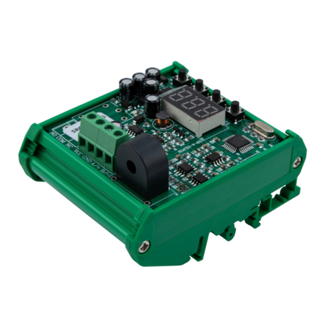
Infinite

Infinite L-com PXCAPCKN Series User manual

Infinite L-com SRCN-C711-1 User manual
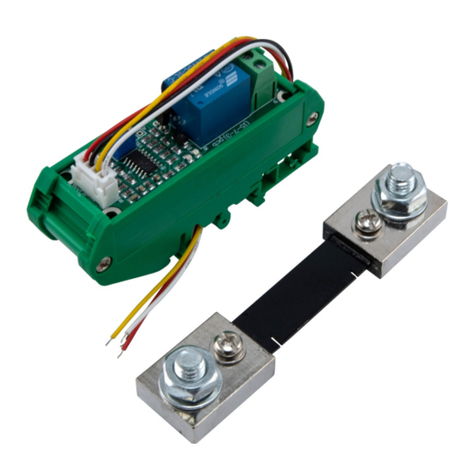
Infinite

Infinite L-com SRCN-C711-1 User manual

Infinite L-com SRCN-C413-3 User manual
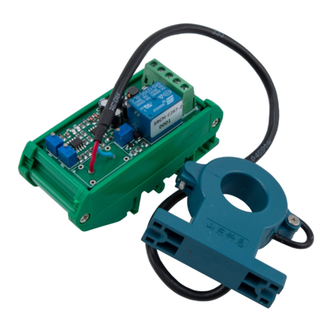
Infinite

Infinite L-com SRCN-C413-3 User manual

Infinite L-com SRCN-C267-2 User manual
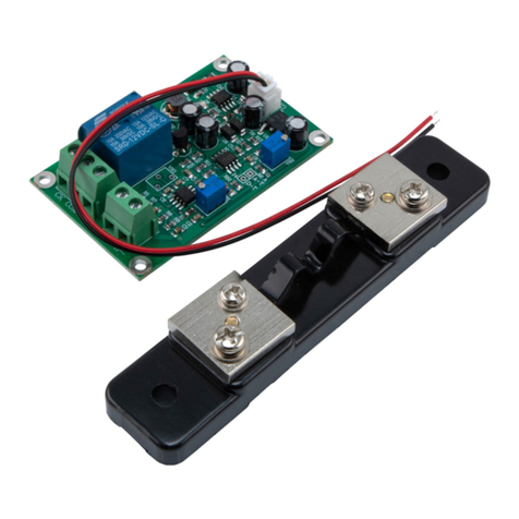
Infinite

Infinite L-com SRCN-C267-2 User manual

Infinite L-com SRCN-C420-3 User manual
Infinite

Infinite L-com SRCN-C420-3 User manual

Infinite AERINOS ADS-260 User manual

Infinite

Infinite AERINOS ADS-260 User manual
Infinite L-com SRAQ-G005 User manual

Infinite

Infinite L-com SRAQ-G005 User manual
Infinite L-com SRCN-C415-2 User manual
Infinite

Infinite L-com SRCN-C415-2 User manual

Infinite L-com SRWQ100-pH104-8701 User manual

Infinite

Infinite L-com SRWQ100-pH104-8701 User manual

Infinite L-com SRCN-C710-1 User manual

Infinite

Infinite L-com SRCN-C710-1 User manual

Infinite L-COM PM18 Series User manual

Infinite

Infinite L-COM PM18 Series User manual

Popular Accessories manuals by other brands

Veeder-Root TLS installation instructions
Veeder-Root

Veeder-Root TLS installation instructions

WBOX Technologies 0E-PIRCM Installation
WBOX Technologies

WBOX Technologies 0E-PIRCM Installation

koban KDP-8MW manual

koban

koban KDP-8MW manual

Pogo Bounce House Tropical Marble 35' Dual Lane Slip N Slide manual
Pogo Bounce House

Pogo Bounce House Tropical Marble 35' Dual Lane Slip N Slide manual

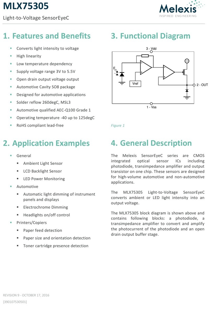
Melexis SensorEyeC Series General description
Melexis

Melexis SensorEyeC Series General description

Panasonic KX-HNS104FX installation guide
Panasonic

Panasonic KX-HNS104FX installation guide

Rice Lake IQ 700IS installation manual

Rice Lake

Rice Lake IQ 700IS installation manual

Aeotec Water Sensor 7 Pro user guide

Aeotec

Aeotec Water Sensor 7 Pro user guide

Domino 1100 RC Fitting and operating instructions

Domino

Domino 1100 RC Fitting and operating instructions

Asus Xtion 2 quick start guide

Asus

Asus Xtion 2 quick start guide

Campbell NR01 instruction manual

Campbell

Campbell NR01 instruction manual

Clearaudio Clarify user manual

Clearaudio

Clearaudio Clarify user manual

Datalogic IO-Link S100 Series instruction manual
Datalogic

Datalogic IO-Link S100 Series instruction manual

Geca CTP21 user manual

Geca

Geca CTP21 user manual

DURAVANT QC Conveyors AS40 Installation operation & maintenance
DURAVANT

DURAVANT QC Conveyors AS40 Installation operation & maintenance

Axis 0736-001 installation instructions
Axis

Axis 0736-001 installation instructions

Atlantic Ultraviolet Sanidyne PREMIUM user guide
Atlantic Ultraviolet

Atlantic Ultraviolet Sanidyne PREMIUM user guide

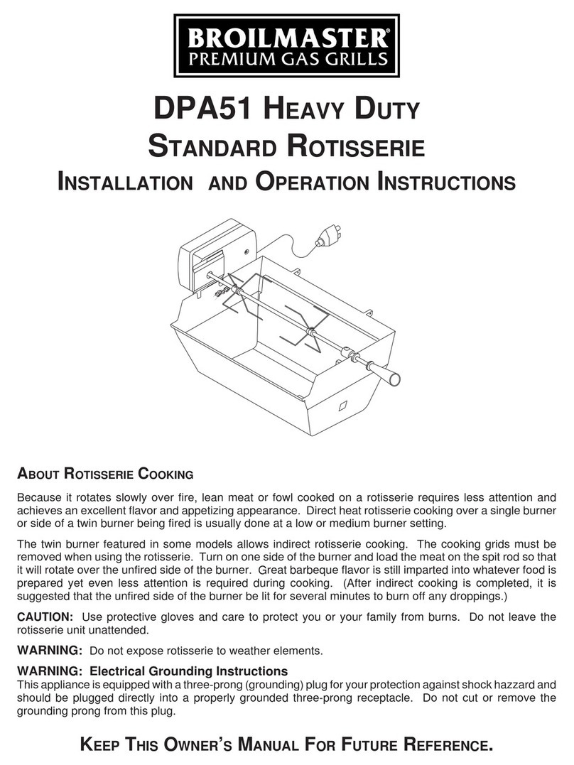
Broil King DPA51 Installation and operation instructions

Broil King

Broil King DPA51 Installation and operation instructions

manuals.online logo
manuals.online logoBrands
  • About & Mission
  • Contact us
  • Privacy Policy
  • Terms and Conditions

Copyright 2025 Manuals.Online. All Rights Reserved.