manuals.online logo
Brands
  1. Home
  2. •
  3. Brands
  4. •
  5. Infinite
  6. •
  7. Security Sensor
  8. •
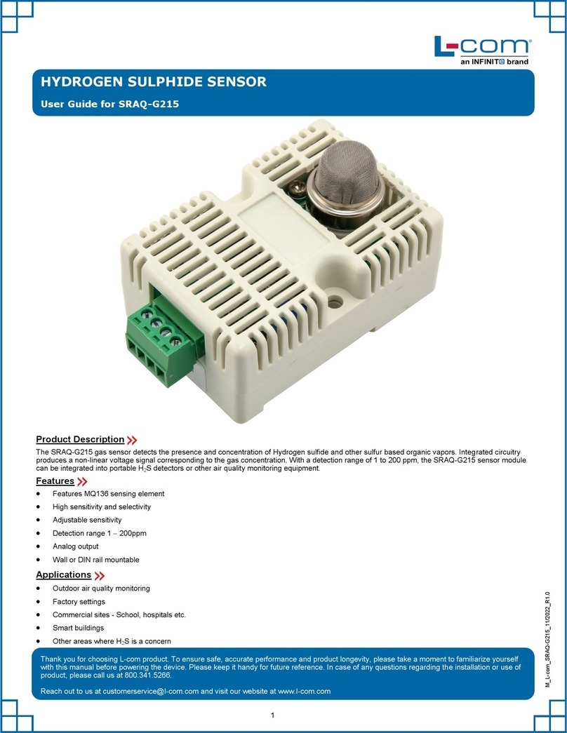
  9. Infinite L-com SRCN-C267-1 User manual

Infinite L-com SRCN-C267-1 User manual

LINEAR AC SENSOR & OVER-CURRENT PROTECTOR
User Guide for SRCN-C267-1
Thank you for choosing L-com product. To ensure safe, accurate performance and product longevity, please take a moment to familiarize yourself
with this manual before powering the device. Please keep it handy for future reference. In case of any questions regarding the installation or use of
product, please call us at 800.341.5266.
Reach out to us at customerservice@l-com.com and visit our website at www.l-com.com
M_L-com_SRCN-C267-1_08/2022_R1.0
1
Product Description
This module is used to measure and monitor current consumption by utilizing electromagnetic current transformer technology. A voltage output is
produced in direct proportion to the measured current. If the current exceeds a preset value, the relay on the module is activated. Uses include
building automation and facility management systems, where acquiring information on energy usage can lead to increased efficiency. They can also
detect equipment issues and help prevent damage by detecting over-current and/or short-circuit conditions.
Features
 Split-core coil
 Measuring range 0  100 A
 CT technology
 High accuracy, ±1% of full scale range
 Analog and relay output with adjustable linear output (0  5 V)
 35 mm DIN rail or board mount
Applications
 Building and facilities management
 HVAC
 Electric fans
 Electric pumps
 Devices requiring over-current & short-circuit protection
Working voltage 24 VDC ± 0.5 VDC
Working current
Before protection ≤ 25 mA
After protection ≤ 90 mA
Working temperature 0  70 °C
Working humidity 10  90% (No condensation)
Detection range 0  100 A
Output mode
Relay output
Analog output
Red LED ON Overcurrent
Alarm mode LED judgement
Red LED OFF Normal
Installation mode
Pedestal Mounting on 35mm DIN rail
Module Mounting with screws
2
Technical Parameters
Output Correlation Table
The corresponding relation table is of the output voltage and the detection current (0  5 V corresponds to 0  100 A).
Electrical Diagram
Vout AVout AVout AVout AVout A
120 240 360 480 5100
Mounting Diagram
35mm DIN rail mounting: Mount the sensor module onto the DIN rail (dark black) as shown in the figure.
Board Mount
Mount the PCB to the enclosure with screws. Mounting hole diameter is 3mm.
3
Notes
1. The module can only be powered by 24 VDC. The module has reverse voltage protection function and power indicator lights (N: green light,
L: yellow light) to help with power connection.
2. Set the current threshold to 2 A. According to corresponding relationship between current and voltage, the corresponding voltage threshold value
is 2 V. Set it at 1.97 V because of circuit characteristics.
3. The modules are tested with pure resistance loads when they leave the factory. If user uses inductive or capacitive loads, the detected current will
be offset. See correction method to set this.
4. For users who have frequent current changes and need to use the relay terminal on the module to control, it is recommended to connect an AC
contactor to the relay output terminal. It will prevent the relay from being frequently activated, which can cause damage.
Correction Method
The VR2 and VR3 potentiometers are factory set, the user cannot adjust them. Only when the module has a large error, recalibrate the two
potentiometers. Following is the correction method:
1. When the module is powered ON, in the case of no current detection, measure the ground voltage at point B of the module, and adjust the
voltage at this point to 0 V through the VR2 potentiometer.
2. Then add a known current such as 2 A, measure the ground voltage of point B, and adjust the voltage at this point to 2 V through the VR3
potentiometer. Calibration is completed.
Other Infinite Security Sensor manuals

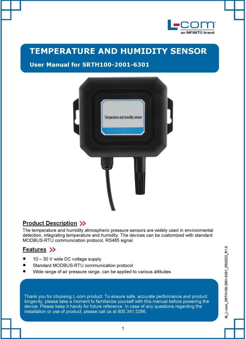
Infinite L-com SRCN-C710-2 User manual

Infinite

Infinite L-com SRCN-C710-2 User manual

Infinite L-com SRCN-C420-1 User manual

Infinite

Infinite L-com SRCN-C420-1 User manual

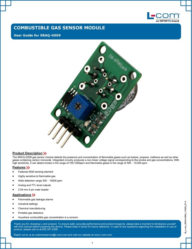
Infinite L-COM SRAQ-G009 User manual

Infinite

Infinite L-COM SRAQ-G009 User manual

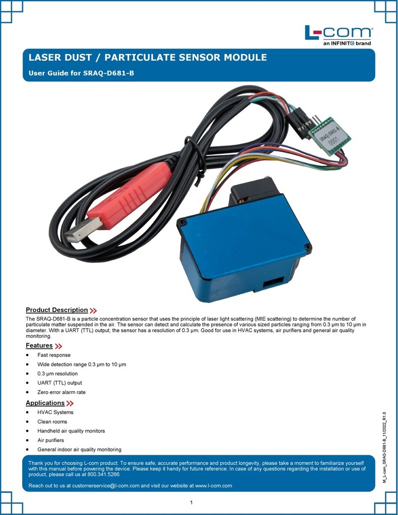
Infinite L-com SRAQ-D681-B User manual

Infinite

Infinite L-com SRAQ-D681-B User manual

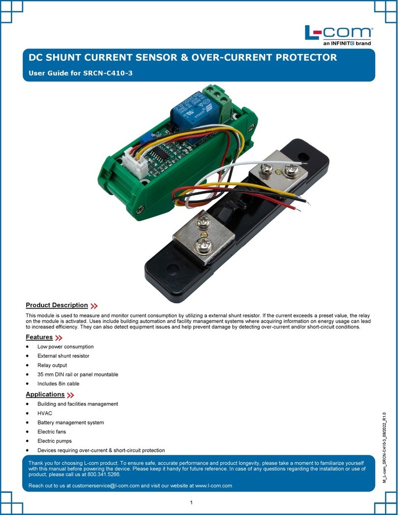
Infinite L-com SRCN-C410-3 User manual

Infinite

Infinite L-com SRCN-C410-3 User manual

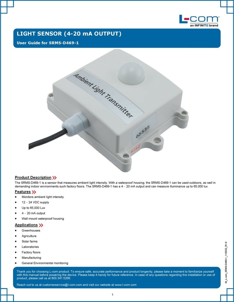
Infinite L-COM SRMS-D469-1 User manual

Infinite

Infinite L-COM SRMS-D469-1 User manual

Infinite L-com LTSUB7002-3202 User manual

Infinite

Infinite L-com LTSUB7002-3202 User manual

Infinite L-com SRCN-C413-2 User manual

Infinite

Infinite L-com SRCN-C413-2 User manual

Infinite L-com SRCN-C423-1 User manual

Infinite

Infinite L-com SRCN-C423-1 User manual

Infinite L-com SRCN-C425-3 User manual

Infinite

Infinite L-com SRCN-C425-3 User manual

Infinite L-com SRAQ-G215 User manual

Infinite

Infinite L-com SRAQ-G215 User manual

Infinite L-com SRTH100-2001-6301 User manual

Infinite

Infinite L-com SRTH100-2001-6301 User manual

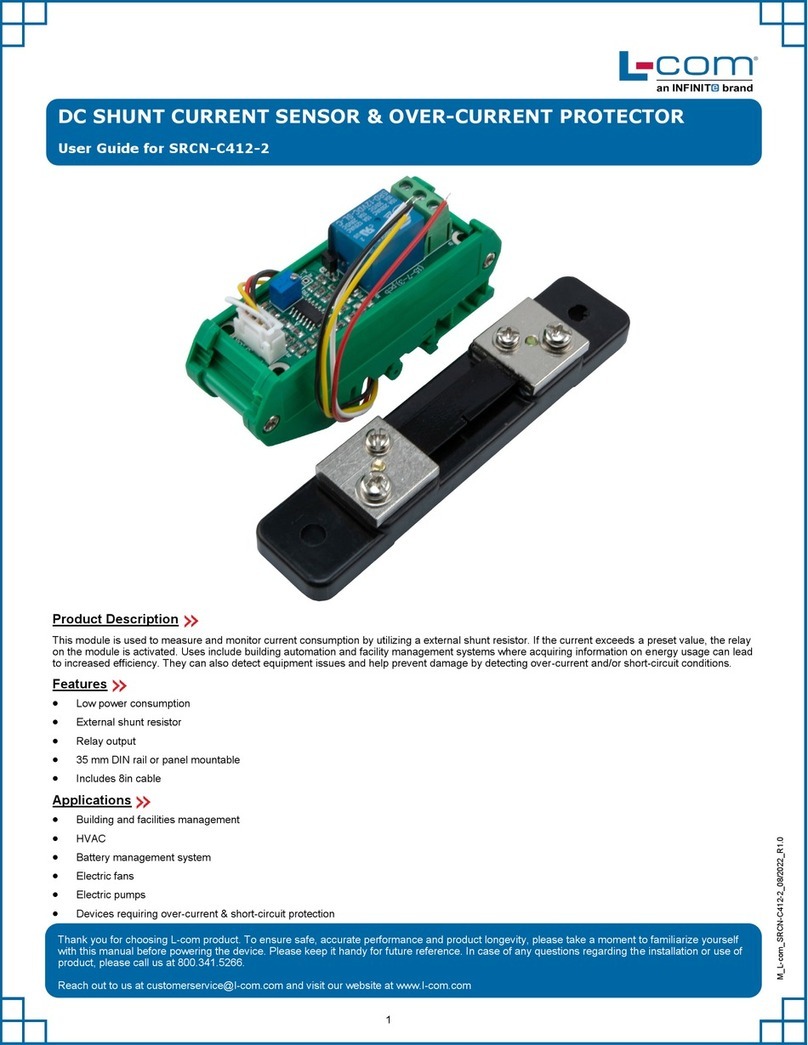
Infinite L-COM SRCN-C412-2 User manual

Infinite

Infinite L-COM SRCN-C412-2 User manual

Popular Security Sensor manuals by other brands

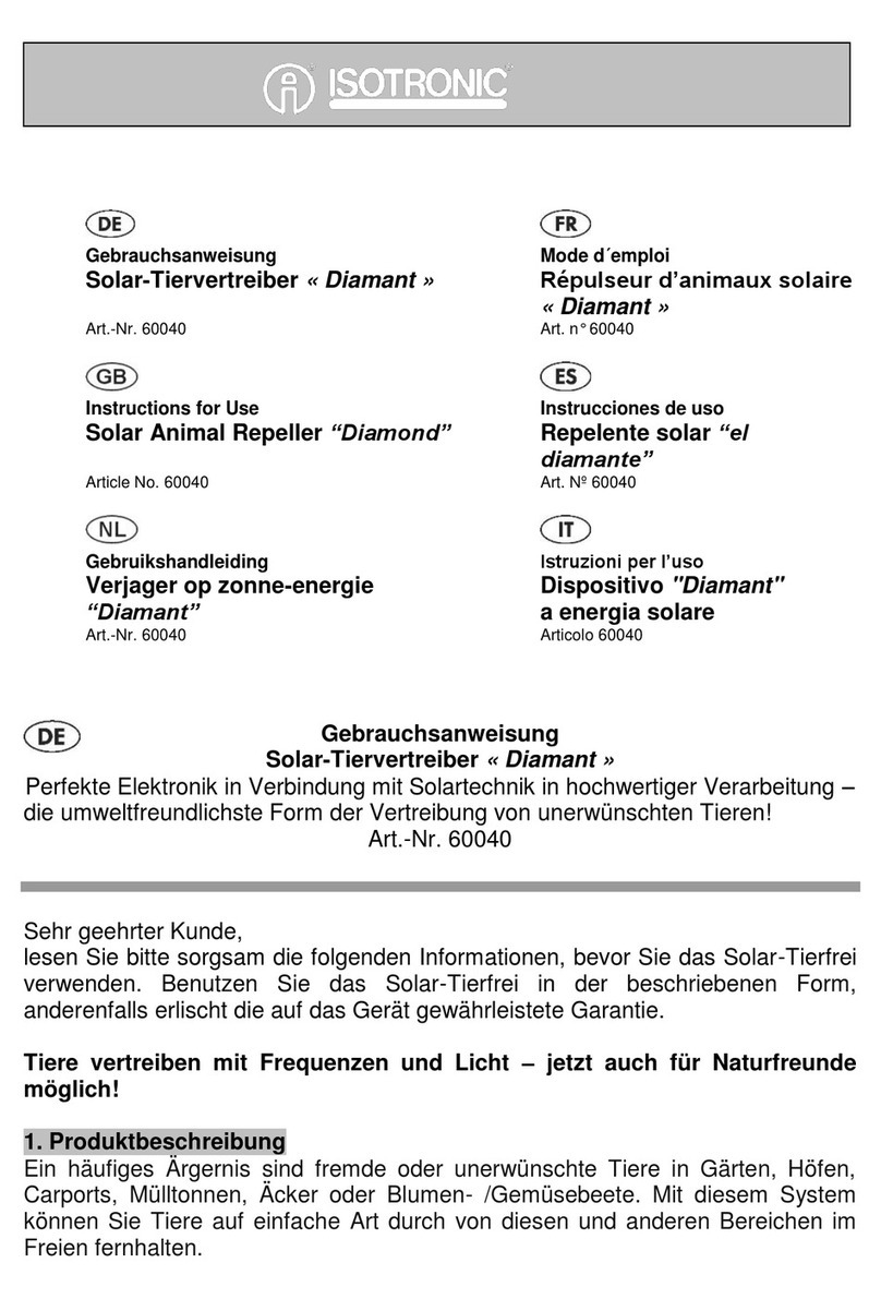
Isotronic 60040 Instructions for use

Isotronic

Isotronic 60040 Instructions for use

yellow jacket 69373 Series Installation and operation manual

yellow jacket

yellow jacket 69373 Series Installation and operation manual

Risco Industrial LuNAR RK200DTG3 installation guide

Risco

Risco Industrial LuNAR RK200DTG3 installation guide

Niko 25421 quick start guide

Niko

Niko 25421 quick start guide

Simplex 2098-9201 Cleaning instructions

Simplex

Simplex 2098-9201 Cleaning instructions

Leica DIGICAT 500i quick start

Leica

Leica DIGICAT 500i quick start

SWARCO MVAS Setup guide

SWARCO

SWARCO MVAS Setup guide

systemax Poolnanny installation guide

systemax

systemax Poolnanny installation guide

SEBSON IR_WAL_B user manual

SEBSON

SEBSON IR_WAL_B user manual

Reed Instruments R5110 instruction manual

Reed Instruments

Reed Instruments R5110 instruction manual

System Sensor B112LP Installation and maintenance instructions

System Sensor

System Sensor B112LP Installation and maintenance instructions

Veeder-Root TLS-3 Series installation guide

Veeder-Root

Veeder-Root TLS-3 Series installation guide

Elko inels RFWD-100 quick start guide

Elko

Elko inels RFWD-100 quick start guide

Sonel TUD-1 user manual

Sonel

Sonel TUD-1 user manual

SKF Lincoln 254-15165-9 Service manual

SKF

SKF Lincoln 254-15165-9 Service manual

TECHNO-AC SUCCESS-438.15N Technical Description, Operating Instructions

TECHNO-AC

TECHNO-AC SUCCESS-438.15N Technical Description, Operating Instructions

Abus FUGB60000 quick guide

Abus

Abus FUGB60000 quick guide

Optex AP-20NB(C) installation instructions

Optex

Optex AP-20NB(C) installation instructions

manuals.online logo
manuals.online logoBrands
  • About & Mission
  • Contact us
  • Privacy Policy
  • Terms and Conditions

Copyright 2025 Manuals.Online. All Rights Reserved.