Infinite L-com SRCN-C710-2 User manual

AC CURRENT SENSOR & OVER-CURRENT PROTECTOR
User Guide for SRCN-C710-2
Thank you for choosing L-com product. To ensure safe, accurate performance and product longevity, please take a moment to familiarize yourself
with this manual before powering the device. Please keep it handy for future reference. In case of any questions regarding the installation or use of
product, please call us at 800.341.5266.
Reach out to us at customerservice@l-com.com and visit our website at www.l-com.com
M_L-com_SRCN-C710-2_08/2022_R1.0
1
Product Description
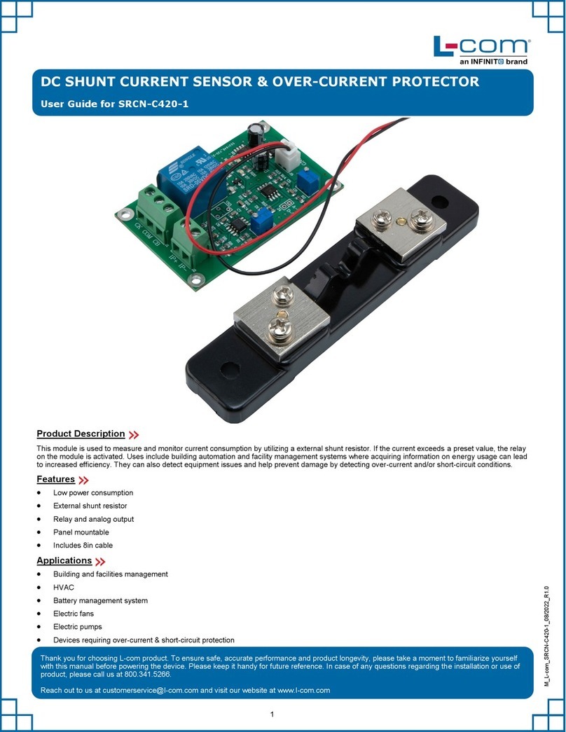
This module is used to measure and monitor current consumption by utilizing current transformer technology. Uses include building automation and
facility management systems where acquiring information on energy usage can lead to increased efficiency. They can also detect equipment issues
and help prevent damage by detecting over-current and/or short-circuit conditions.
Features
Multi-function menu
Digital display
CT technology
Analog output
Low power consumption
35mm DIN rail or panel mountable
Applications
Building and facilities management
HVAC
Electric fans
Electric pumps
Devices requiring over-current & short-circuit protection

Working voltage 10 28 VDC
Power consumption < 0.8 W
Working temperature 0 70 °C
Working humidity 10% 90% (No condensation)
Detection range 0 5 A
Function menu Select required functions via keys on module
Output mode Analog output 0 5 V
Pedestal Mounting on 35mm DIN rail
Installation mode
Module Mounting with screws
2
Technical Parameters
Electrical Diagram
Terminal
Terminal Description
Analog output
VCC 10 ~ 28 VDC
GND Power ground wire
A/+ Analog signal output
B/- Analog signal ground
NO Relays normally open
COM Relay common end
NC Relays normally closed
Output Correlation Table
The corresponding relation table is of the output voltage and the detection current (0 5 V corresponds to 0 5 A).
Vout AVout AVout AVout AVout A
1122334455

Board Mount
Mount the PCB to the enclosure with screws. Mounting hole diameter is 3mm.
3
Mounting Diagram
35mm DIN rail mounting: Mount the sensor module onto the DIN rail (dark black) as shown in the figure.
Notes
1. The module has the function of anti-reverse connection. But it is still necessary to pay attention to the voltage polarity when the power is turned
ON to avoid damage to the module.
2. The modules are tested with pure resistance loads when they leave the factory. If user uses inductive or capacitive loads, there can be deviation
in the reading. Kindly contact the customer support team for assistant.
3. When the module is connected to the computer for debugging, please use the USB to 485 modules for debugging.

4
Function Menu Description
Press and hold the SET button for 3 seconds and release it to enter the function menu interface (F01-F09). Press the + and - buttons to switch in
between menus. Select the menu and click the SET button to enter the setting state. The display starts flashing. Set the data with + and - keys, long
press the SET key to automatically save the data and exit. It will return to the original current interface. If the selected function is wrong, user can click
the ESC key to return to the function menu selection interface to re-select.
For details of the function menu interface, see the following table:
Note: If user do not want to use a particular function, kindly set the parameter to 000 to close the particular function.
Function Menu
Number Menu Feature Description
F01 Current upper limit setting: (Range: lower limit ~ range): When the lower limit function is closed, the range is: > 0 ~ range.
After setting the parameter, if the detected current exceeds the parameter, the relay on the module will act (pull in).
F02 Current lower limit setting: (Range: > 0 ~ upper limit): When the upper limit function is closed, the range is: > 0 ~ range.
After setting the parameter, if the detected current is lower than the parameter, the relay on the module will act (pull in).
F03
Power-on delay time setting: (Range: 0.01S ~ 99.9S)
Power-on delay means, after the module is powered ON, the module does not do any checks within the delay time. It is mainly used
to avoid the instantaneous flow of current of the device when the module and the device under test are powered ON at the same
time, causing the relay to act (pull-in).
F04
Delay protection time setting: (Range: 0.01S ~ 99.9S)
Delay protection means that after the current detected by the module exceeds the set current value and the duration exceeds the
set time, the module relay will act (pull in).
F05
Delay recovery time setting: (Range: 0.01S ~ 99.9S)
Delay recovery means that the current detected by the module exceeds the set current value. After the relay acts (closes) and the
current returns to normal, the relay does not releases immediately, but continues to attract until the set time and then the relay
releases.
An extended function is added to this function: When this time is set to OFF, after the relay acts, it will not recover by itself, and it
needs to be recovered manually.
OFF setting method: After entering the setting interface of this function menu, click the SET button to move the blinking cursor to the
highest position, and keep pressing the + button until OFF is displayed. Press and hold the SET button to save and exit.
When the relay on the module operates, regardless of the current, the relay does not releases automatically. The relay state can
only be restored manually.
OFF closing method: After entering the function menu setting interface, directly press the - key to display 99.9, and then use the
SET key to change positions and +/- keys to set the required time.
Manually restore the setting: When the detection current returns to normal, press and hold the ESC key. The relay can return to its
initial state.
F06
Transformer winding turns setting: Default: 001
In the actual use process, if the current line is passed through the transformer for 2 turns, the current of 1 A will be displayed as 2 A.
At this time, when the parameter is set to 2, the display shows the actual current of 1 A.
Note: This parameter can only be used when the transformer is threaded, the number of the parameter should be set the
same with the number of the turns threaded.
F07 Range display: Used to display the maximum current range of the module.
Note: This parameter cannot be changed by the user at will. Otherwise, it will cause test errors.
F08 Relay action record: This item saves the current value of the last action of the relay on the module. It is only for viewing and cannot
be set.
F09 ID display: This function is only used when the module has RS485 output. User can check the module ID through this function or
user can directly set the ID through the + and - keys on the function interface. No need to connect to a computer.
Key Function Description
SET key
Press and hold 3S to enter the function menu interface. After selecting, click this key to enter the setting interface. After entering
the setting interface, click this key to perform the cursor transposition operation. After the setting is completed, press and hold for
3S to automatically save the data and exit.
+ Key Used after entering the function menu or function setting interface.
- Key Used after entering the function menu or function setting interface.
ESC key After performing the wrong operation, click this key to return to the previous menu immediately, and the data will not be saved.
In the relay manual recovery mode: after the current returns to normal, long press this key to restore the initial state of the relay.
RS485 Modbus - RTU Protocol
The protocol adopts the standard Modbus-RTU protocol, only open 03 and 06 function codes, all commands and replies are in Hex (hexadecimal)
format. Factory ID default: 01
The CRC check is calculated in reverse order of A001 or 8005, and the calculation code is shown in the attachment.
The communication setting format is as follows:
Baud rate Data bits Check bits Stop bits
9600 (default) 8 bits None 1 bit

5
Register Description
Note: For detailed functions of the below registers, please refer to the function menu description.
Register Illustrate R/W
0x00 Current data register, resolution: 1mA R
0x01 Relay status register, display the status of relay operation R/W
0x64 ID registers, range: 1 ~ 247 R/W
0x65
Baud rate
R/W
00 01 02 03 04 05 06 07 08 09
1200 2400 4800 9600 19200 38400 76800 115200 128000 256000
0x66 Current upper limit, range: lower limit ~ range, set to 0, turn off the upper limit alarm output function R/W
0x67 Lower current limit, range: 0 ~ upper limit, set to 0, turn off the lower limit alarm output function R/W
0x68 Power-on delay, range: 0 ~ 999, resolution: 0.1S R/W
0x69 Delay protection time, range: 0 ~ 999, resolution: 0.1S R/W
0x6A Delay recovery time, range: 0 to 999, resolution: 0.1S
When the value is written to ≥ 1000, it means that the relay is in manual recovery state. For details, see function menu F05. R/W
0x6B Transformer threading turns R
0x6C Module maximum range R
Data Read Format
ID Function Code Register Address The Number of Registers CRC Check
1 byte 1 byte 2 bytes 2 bytes 2 bytes
1-247 (Decimal) 03 — 0x0001 Low in front
Example: Current Data Read
ID Function Code Register Address The Number of Registers CRC Check
1 byte 1 byte 2 bytes 2 bytes 2 bytes
1-247 (Decimal) 03 0x0000 0x0001 Low in front
1-247 (Decimal) 03 00 00 00 01 84 0A
The module response data format is as follows:
ID Function Code Data Length Current Data CRC Check
1 byte 1 byte 1 byte 2 bytes 2 bytes
1-247 (Decimal) 03 2The data is high The data is low Low in front
The calculation method is: (Data high order * 256 + Data low order) * 0.001 Unit: A
Relay Status Read
ID Function Code Register Address The Number of Registers CRC Check
1 byte 1 byte 2 bytes 2 bytes 2 bytes
1-247 (Decimal) 03 0x0001 0x0001 Low in front
1-247 (Decimal) 03 00 01 00 01 CRC low CRC high
Module response data format: overcurrent means the relay is closed.
ID Function Code Data Length Current Data CRC Check
1byte 1 byte 1 byte 2 byte 2 byte
1-247 (Decimal) 03 02
0x0000 Non-overcurrent
Low in front
0x00FF Over current

6
Data Write Format
ID Function Code Register Address Write Data CRC Check
1 byte 1 byte 2 bytes 2 bytes 2 bytes
1-247 (Decimal) 06 ——Low in front
When the data returned by the module is consistent with the data sent, the relay is unlocked.
Tips: The ID range in the command is in decimal format, please convert it to Hex (hexadecimal) format when using it.
When user do not know the module ID, user can view or modify the ID directly through the function menu F09. User can also check the ID through the
following commands:
ID Function Code Register Address Write Data CRC Check
1 byte 1 byte 2 byte 2 byte 2 byte
FA 03 0x0064 0x0001 D0 5E
This command can only be used in stand alone state.
The returned data is as follows:
ID Function Code Data Length ID CRC Check
1 byte 1 byte 1 byte 2 byte 2 byte
xx 03 200 xx Low in front
“xx” is the ID of the module here.
Attachment: CRC check code
Function: CRC check function, generate CRC
Parameter description: arr_buff: array set to be verified
len: the length of the data to be checked
Return parameter: CRC is unsigned int type, High-order byte is high-order first, low-order last.
unsigned int CRC_Compute (unsigned char *arr_buff, unsigned char len)
{
unsigned int crc=0xFFFF; unsigned char i, j;
for ( j=0; j <len;j++)
{
crc=crc ^*arr_buff++; for ( i=0; i<8; i++)
{
if( ( crc&0x0001) >0)
{
crc=crc>>1; crc=crc^ 0xa001;
}
else
crc=crc>>1;
}
}
return ( crc);
Table of contents
Other Infinite Security Sensor manuals
Infinite
Infinite L-com SRCN-C425-3 User manual
Infinite
Infinite L-com SRTH100-2001-6301 User manual
Infinite
Infinite L-COM SRMS-D469-1 User manual
Infinite
Infinite L-com SRCN-C410-3 User manual
Infinite
Infinite L-com SRCN-C267-1 User manual
Infinite
Infinite L-COM SRCN-C412-2 User manual
Infinite
Infinite L-com LTSUB7002-3202 User manual
Infinite
Infinite L-com SRCN-C423-1 User manual
Infinite
Infinite L-com SRAQ-D681-B User manual
Infinite
Infinite L-com SRCN-C413-2 User manual
