Infoscan FV5X User manual

infoscan FV5X
Operating Manual
NANJING BILIN INTELLIGENT IDENTIFICATION TECHNOLOGY CO., LTD
www.infoscan.com.cn
Tel:400-700-6288
Ver:20220426

2
Catalogue
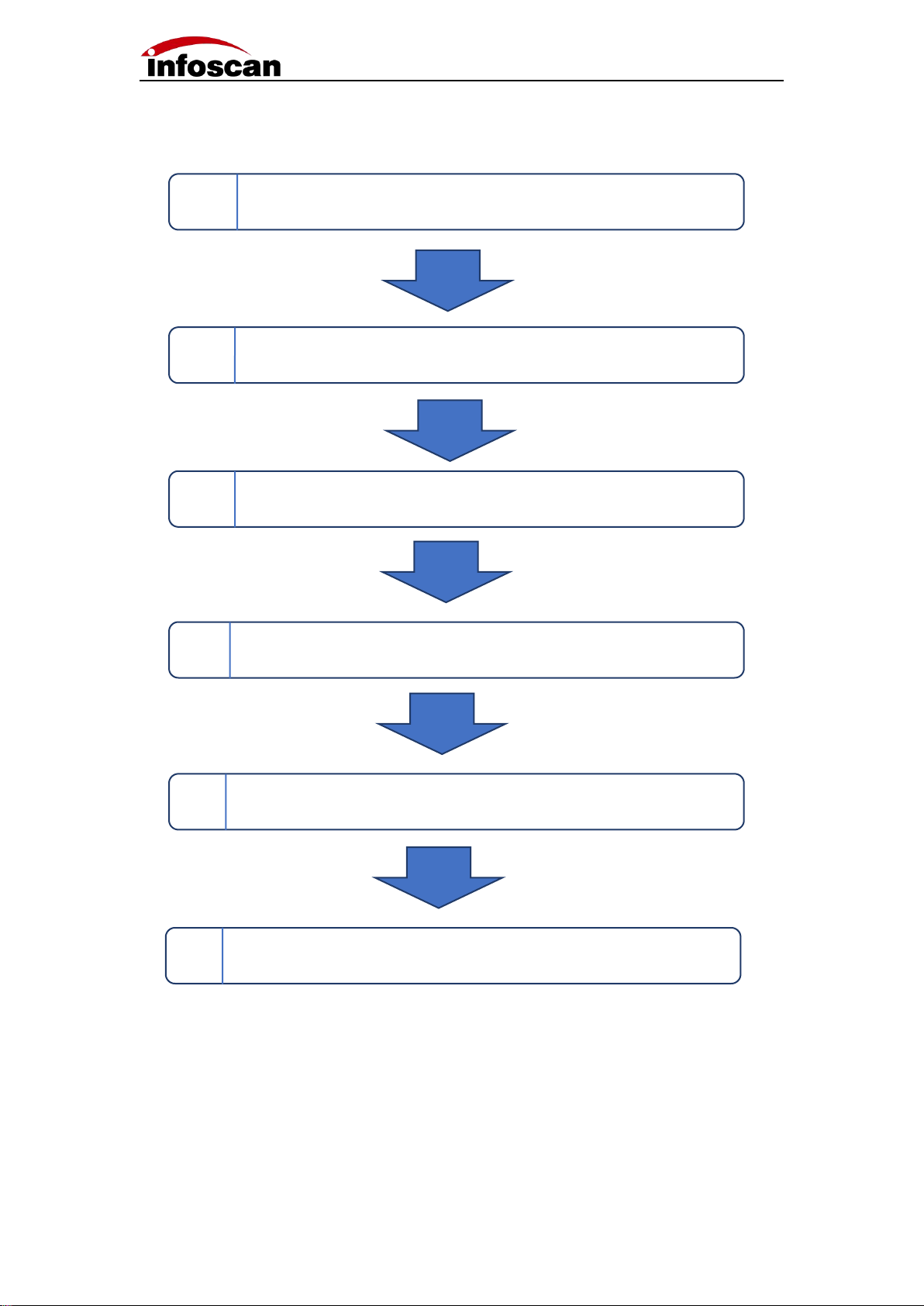
Setup Process .......................................................................................................................4
1 Unwrapping the Package .................................................................................................. 5
1-1 Scanner and its belonging ...................................................................................... 5
1-2 Cables and Power Adapter ..................................................................................... 6
1-3 Scanner Photographs:..........................................................................................7
1-4 Scanner Configuration:.........................................................................................8
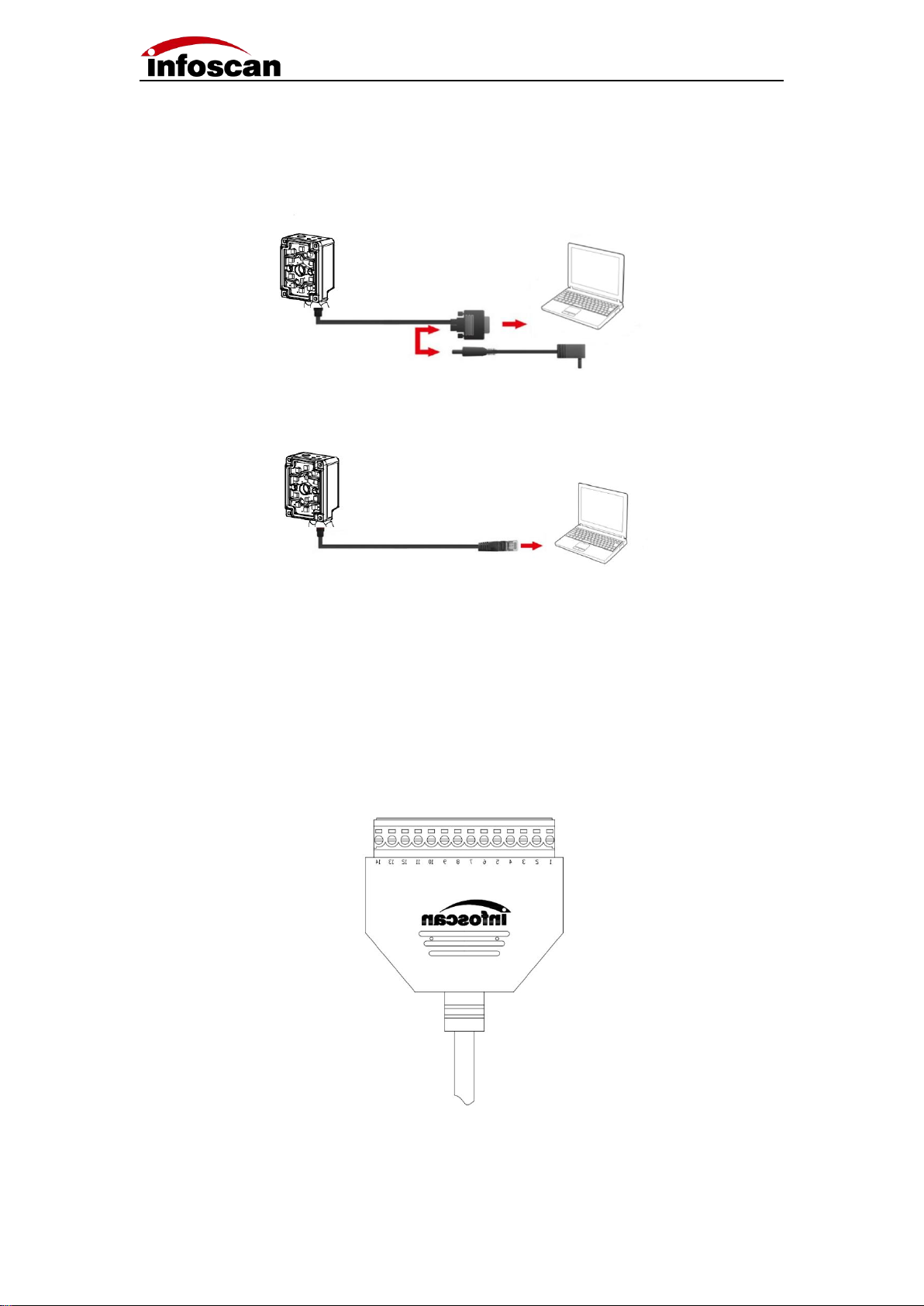
2 Connecting Diagram .......................................................................................................... 9
2-1 Cable connection Diagram ......................................................................................9
2-2 Connecting to Computer ....................................................................................... 10
2-3 I/O connection diagram .........................................................................................10
2-4 Input Wiring Diagram ............................................................................................ 12
2-5 Output Wiring Diagram ......................................................................................... 13
2-6 Power Input Diagram ............................................................................................ 14
3 Installation and Adjustment ..............................................................................................15
3-1 Before Installation ................................................................................................. 15
3-2 Installation Diagram .............................................................................................. 15
3-3 Angle Adjustment .................................................................................................. 16
3-4 Product Dimensions .............................................................................................. 16
3-5 Reading Performance Chart ................................................................................. 17
4 Connecting FV53 to infostepper ......................................................................................18
4-1 Introduction to infostepper .................................................................................... 18
4-2 Connecting FV5X to infostepper ...........................................................................19
4-2-1 RS-232 Connection .................................................................................... 19
4-2-2 Ethernet(TCP/IP)Connection ................................................................ 20
4-2-3 USB Connection ......................................................................................... 21
5 How to quickly Setup FV5X without infostepper ............................................................. 22
6 How to Set up FV5X with infostepper ............................................................................. 23
6-1 Focusing-on adjustment ........................................................................................23
6-2 Getting a Clear Image ...........................................................................................24
6-3 Image Parameters Setting .................................................................................... 25
6-4 RS232 Parameters Setting ................................................................................... 26
6-5 Ethernet Parameters Setting ................................................................................ 28
6-6 Setting the Output Signal Level, Duration Pulse Width ....................................... 29
6-7 Setting the Minimum Valid Trigger Time ............................................................... 30
6-8 Setting the Buzzer and Laser Aiming Function while Good or Failure Reading . 30
6-9 Trigger Command Generating and Cancelling .....................................................31
6-10 Generating the Failure Feedback Command ..................................................... 32
6-11 Rereading the Same Barcode .............................................................................33
6-12 Setting the Barcode Filter Parameters ............................................................... 34
6-13 Auto-induced Reading Mode .............................................................................. 35
6-14 Continuous Trigger Mode ....................................................................................36
6-15 Auto-tuning Function ........................................................................................... 37

3
6-16 Selecting the Readable Symbologies .................................................................38
6-17 How to Get the Pictures of A Barcode ................................................................ 39
6-18 How to Generate Setting Codes for the Selected Parameters for Cloning Other
Scanners ......................................................................................................................40
6-19 How to Save and Operate the Configuration File .............................................. 41
7 Settings for special applications ......................................................................................42
7-1 How to read multiple barcode in the same time ................................................... 42
7-2 How to position and sort the barcodes ................................................................. 43
7-3 Defining the Prefix or Suffix .................................................................................. 45
7-4 the Logic Diagram of IO Output ............................................................................ 47
7-5 How to read a color-reversed barcode ................................................................. 48
7-6 How to Read Dot-matrix Barcode .........................................................................49
7-7 How to Read Small-sized or Defaced DM Barcode ............................................. 50
7-8 How to use the polling algorithm for complicated reading ................................... 52
8 Other settings ...................................................................................................................53
8-1 To View Decoded Data after Settings ...................................................................53
8-2 How to Trigger the Scanner by Computer Command ..........................................54
8-3 How to simulate keyboard input ............................................................................55
8-4 How to Check the Reader Firmware Version Information ....................................56
8-5 How to Reset the Scanner to Factory-default Settings ........................................57
8-6 How to convert characters to Hex code ............................................................... 58

4
Setup Process
1 Check packaging materials
2 Wiring and installation
3 Connecting the power adapter
4 Connecting FV5X to computer and running the infostepper
5 Briefly setting up FV53
6 Detailed setting and running

5
1 Unwrapping the Package
1-1 Scanner and its belonging
Model
Name
Package content
Quantity
Picture
FV53
Industrial
scanner
Scanner
1
Quick Use Guide
1
Installation plate
1
Insulating gasket
1
Screws
1

6
1-2 Cables and Power Adapter
(Please refer to the customer's actual order for product accessories)
Name
Package content
Model
Quantity
Picture
Cable
Serial
communication
cable
H12S-0.85M-USBD9P
F14-V1
1
Ethernet
communication
cable
H8S-2M-RJ-V1
1
Power
Power adapter
WT48-2402000-T
1

7
1-3 Scanner Photographs:
1
Camera lens
2
Laser aimer
3
Reading failure indicator(red)
4
Reading success indicator(bule)
5
Non polarization
6
Polarization
7
12 PIN Aviation jack(Serial communication、power supply、I/O)
8
8 PIN Aviation jack(Ethernet)
9
Trigger button
10
CIR2(Custom)
11
G/F(Reading success indication blue/Reading failure indication red)
12
CIR1(Custom)
13
PWR (Power indication)
14
M3 mounting hole

8
1-4 Scanner Configuration:
Setting up configurations:
Data communication`:
Ethernet
USB
RS322
Ethernet
I/O
USB

9
2 Connecting Diagram
2-1 Cable connection Diagram
1. Connect the aviation plug (male) of the cable to the aviation plug (female) of the code
reader. Fv5x provides two interface terminals, 12 cores and 8 cores. Be sure to
connect accurately。
2. Rotate the aviation plug (male) screw clockwise to fix it。
3. After the aviation cable plug (male) is firmly connected with FV5X, then the serial
communication cable DB9 (female) is connected to the PC serial port, and the
Ethernet communication cable RJ45 is connected to the PC Ethernet port (see
computer wiring for details)。

10
2-2 Connecting to Computer
Connecting computer via serial port (DB9):
Connecting computer via Ethernet (RJ45):
2-3 I/O connection diagram
The I / O terminal is located on the serial communication cable. If the equipment is
connected to external signals or to drive external equipment, it is necessary to use this
terminal to connect with external equipment. The drawing of the terminal is shown as
below, and the serial number and definition of the terminal are shown in the table。

11
Note①: It depends on the voltage of the power supply connected to the serial port cable.
Note②: The effective level value can be set, and the default is 24VDC.
Serial
number
Terminal
name
Describe
Remarks
1
24V
Power input / output
Power output: it can supply power to external
equipment (note ①) power input: it can be connected
to 20-30v for power supply
2
GND
GND
GND
3
IN1
Input signal 1
Logic level ( The default low level takes effect )
4
IN2
Input signal 2
Logic level ( The default low level takes effect )
5
GND
GND
GND
6
COM-IN
Voltage output (+)
It forms voltage feedback with out1-out2,
5V \ 24V \ external voltage (no more than 36VDC)
7
OUT1
Transistor output 1
Optional internal pull-up and effective level (note ②)
8
OUT2
Transistor output 2
Optional internal pull-up and effective level (note ②)
9
NC
10
NC
11
NC
12
GND
GND
GND
13
GND
GND
GND
14
24V
Power input / output
Power output: it can supply power to external
equipment (note ①) power input: it can be connected
to 20-30v for power supply

12
2-4 Input Wiring Diagram
1.NPN photoelectric sensor wiring;
The equipment defaults to the initial logic. The photoelectric sensor shall be NPN type,
and the photoelectric sensor shall be connected to signal terminals 1, 2 and 3. The
corresponding line sequence is shown in the table:
Photoelectric sensor
Terminal
+(L+)
1(DC24V)
-(M)
2(GND)
¬Q
3(IN1)
Note: The high level voltage of input terminal is ranged from 5v to 24v。
2.Switch connection;
The switch connection defaults to the initial logic. Connecting the switch to signal
terminals 2 and 3, and when the switch is pressed, the trigger takes effect. The line
sequence is shown in the table below:
3.Relay trigger wiring;
The equipment defaults to the initial logic and the relay is connected to signal terminals 2
and 3. When the rated voltage is applied, the trigger takes effect. The corresponding line
sequence is shown in the table below:
Push button switch
Terminal
SW1
2(GND)
SW2
3(IN1)
Relay
Terminal
Open node 1
2(GND)
Open node 2
3(IN1)

13
2-5 Output Wiring Diagram
1.Alarm lamp wiring;
The device defaults to the initial logic and connecting pin 14 (24V) of the 14pin terminal to
the com-in terminal. Meanwhile, the positive pole of the load (taking the NPN alarm lamp
as an example) is connected to the com-in terminal and the negative pole is connected to
the out1 or out2 in output terminal. When reading is successful, the green light is on, and
when reading fails, the red light is on and the alarm sounds. The corresponding table of
line sequence is as follows:
Note: The standard working current of output load is 350mA, and the maximum
working current is 400mA.
2.External load relay feedback wiring;
The device defaults to the initial logic and connecting the pin 14 (24V) of the 14pin
terminal to the com-in terminal. At the same time, the relay coil end 1 is connected to the
com-in terminal and the coil end 2 is connected to the out 2 of the terminal. When reading
fails, the relay is actuated.
Relay
Terminal
Coil end 1
6(COM-IN)
Coil end 2
8(OUT2)
Alarm lamp
Terminal
+(Power input line)
6(COM-IN)
-(Green light)
7(OUT1)
-(Red light/Buzzer)
8(OUT2)

14
2-6 Power Input Diagram
1.Adapter power supply wiring;
The power supply interface is located on the serial communication cable DB9 (female),
connecting the adapter output end to the power supply interface of cable DB9.
2.Terminal power supply wiring;
Power supply can be wired in via serial port communication cable 14pin terminal strip. In
the terminal, No. 1 and 2 or No. 14 and 13 can be used as power supply interface. See 2-3
IO terminal diagram for pin No. and definition.

15
3 Installation and Adjustment
3-1 Before Installation
Before installation, please pay attention to the following items and check the installation
conditions:
1. No influence of ambient light;
Please avoid sunlight, other lighting, photoelectric sensors and other ambient light from
entering the FV5X light receiving window, otherwise it may cause reading instability or
reading error.
2. Check whether the light source of the code reader is blocked;
If the light source is blocked, the barcode may not be detected. If there are other devices
emitting strong light (direct light and reflected light) on site, please set up a shading plate
to avoid that such strong light may damage the code reader or cause code reading failure.
3-2 Installation Diagram
Use the mounting bracket to obtain the most appropriate reading position. The figure
shows the most common installation configuration. The installation position of L-type
metal fixing plate can be adjusted according to the actual needs.

16
3-3 Angle Adjustment
As shown in the figure, adjusting the angle of the equipment to the appropriate angle
position, and fixing the L-shape firmly with screws.
3-4 Product Dimensions
Unit:mm

17
3-5 Reading Performance Chart
FV5X
unit:mm
Bar code specification
FV51N
FV51L
FV53
Nearest
reading
distance
Maximum
reading
distance
Nearest
reading
distance
Maximum
reading
distance
Nearest
reading
distance
Maximum
reading
distance
3.34mil Code 128 10bit
45
122
80
155
38
130
5mil Code 128 10bit
40
170
75
180
35
190
6.67mil Code 128 10bit
28
220
60
200
35
250
10mil Code 128 10bit
28
260
45
235
35
330
15mil Code 128 10bit
35
339
50
270
60
400
20mil Code 128 10bit
45
430
60
310
80
500
5mil DataMatrix 10bit
57
85
88
120
35
70
6.67mil DataMatrix 10bit
40
115
80
150
35
95
10mil DataMatrix 10bit
32
188
60
175
35
170
15mil DataMatrix 15bit
30
230
55
200
30
270
Installation distance
FV51N
FV51L
FV53
X-axis
Y-axis
X-axis
Y-axis
X-axis
Y-axis
35
25
19
/
/
26
30
45
33
24
25
28
30
23
50
33
27
27
21
35
27
100
67
53
52
41
70
55
150
103
80
76
61
105
82
200
136
108
104
81
140
110

18
4 Connecting FV53 to infostepper
4-1 Introduction to infostepper
Serial number
Instruction
1
Common Toolbar
2
Connection mode and information display
3
Online feedback information display
4
Once online, set the class
1
2
3
4

19
4-2 Connecting FV5X to infostepper
4-2-1 RS-232 Connection
After the device is directly connected to the computer serial port, check "Device
Manager→""Port", confirm the port number and click "Connect" .When successfully
connecting to the software, then the "Connect to device" window will pop up, selecting
"Serial Port Settings", then click "Port Number" Select the corresponding COM number
below. If the COM number is not displayed, you can click the "Refresh" button to search;
the baud rate, data bit, stop bit, etc. are consistent with the device; as shown in the figure:
Click "Connect to device" after the connection is successful, the device will have a buzzer
prompt, as shown in the figure:
Note:The image can only be viewed under the Ethernet connection

20
4-2-2 Ethernet(TCP/IP)Connection
After the device is directly connected to the computer, go to "Control Panel" → "Network
and Internet" → "Network Connections" → "Ethernet Properties" → "TCPIPv4 Properties"
→ "Use the following IP address" to modify the computer's IP address parameters, so that
the IP of the computer and the device (default 192.168.0.100) are in the same network
segment.
Click "Connect" to pop up "Connect to device", select "Ethernet Settings", select the
computer network card, and click "Search Device", as shown in the figure:
Click "Connect to device" after the connection is successful, the device will have a buzzer
prompt, as shown in the figure:
Note: Display online device model and version information and connection method,
device IP address and port number information; the feedback information part
displays the date and time of the connection and other related information; after the
connection is successful, the interaction is successful, you can click "Image" or
"Setting" ”Make relevant detailed settings for the barcode reader.
Table of contents
Other Infoscan Scanner manuals