Infotel M60 User manual

1
The Packs Infotel
GSM Converter V2
Installation Manual V7

2
Index
Connecting the M60 to the GSM Converter 3
1. GSM Converter description 4
2. Equipment installation 4
3. Led functions. 5
4. GSM Converter start up. 5
5. Telephone line functioning. 5
5.1. Telephone line input. 5
5.2. Telephone line output. 6
5.3. Telephone line monitoring. 6
5.3.1. Line voltage verification. 6
5.3.2. Tone voltage verification. 6
5.4. Incoming Calls 6
6. Working without a telephone line 7
6.1. Telephone line outputs. 7
6.2. GSM converter line characteristics 7
6.3. Outgoing GSM telephone operation. 7
6.4. Restoring of PSTN line. 7
7. Function programming 8
8. Specification 9
3
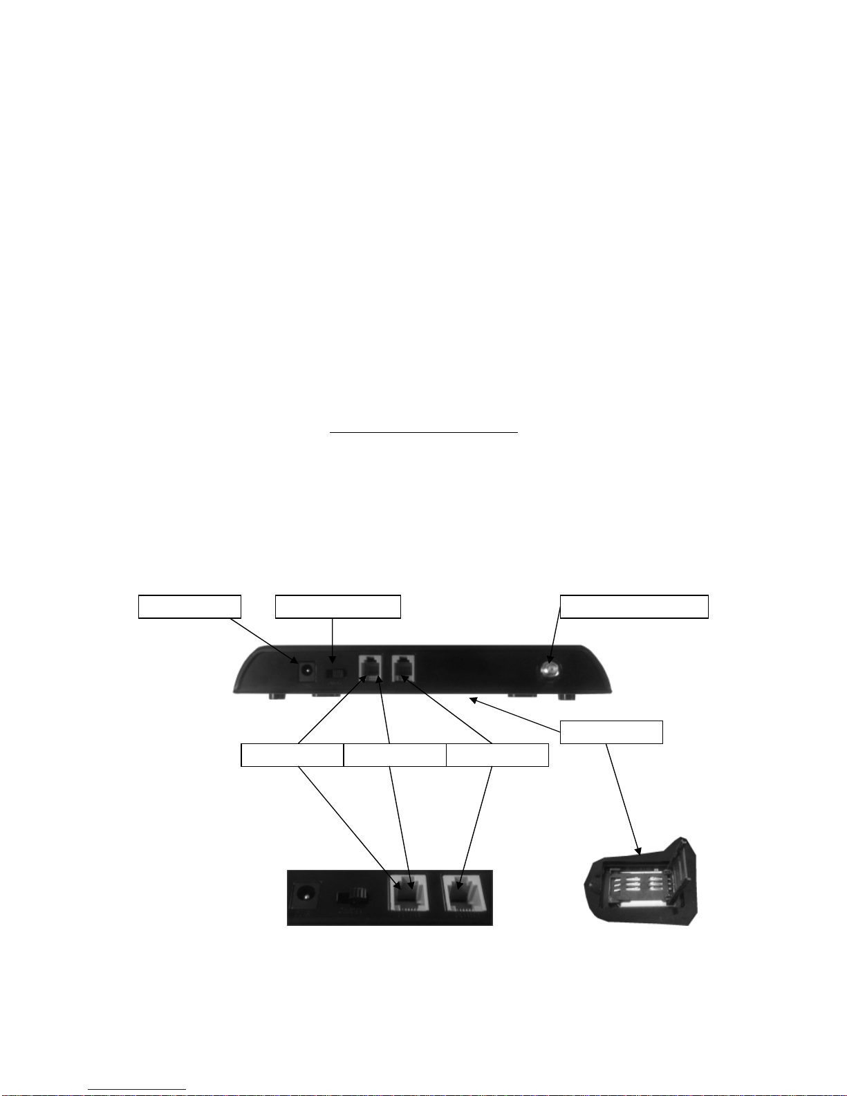
Connecting the M60 to GSM converter
Aerial Connection:
Screw either a fixed ‘flex’ aerial or an external aerial onto the aerial connection on
top of the GSM converter. (Note: if the unit is to be installed inside a metal enclosure then the aerial must
be placed outside the enclosure).
Incoming Land Line (if applicable):
Connect your PSTN telephone line to the lead marked PSTN
or the RG11 Socket marked <POST2>.
M60 Connection:
The M60 Autodialer uses the GSM network full time.
•Connect the M60’s telephone A & B terminals to the Lead marked M60 or the
RG11 Socket marked <POST1>.
Automatically switch to GSM network in the case of a land line failure
•Connect the M60’s telephone A & B terminals to the Lead marked M60 or the
RG11 Socket marked <POST1>.
240 VAC Power Connection:
The GSM Converter comes with its own 240 VAC to 12VDC plug in
power supply and internal battery back up facility. Plug the transformer into your wall socket and the
output plug into the rear of the unit.
Other Power options are available.
12 VDC Power Connection:
If you do not wish to use the supplied 240vac power supply then you
need to connect a supply of 12 VDC to the power socket on the rear of the unit. Polarity: Positive = internal
pin - Negative = external shield.
SIM Card:
Fit either a contract or ‘pay as you go’ SIM into the SIM card holder on the rear of the unit
as indicated on the diagram below.
Notes:
•The GSM converter accepts SIMs from any network.
•Before fitting the SIM make sure any pin’s are disabled and the voice mail service is
turned off.
•We recommend a contract SIM as this eliminates the possibility of running out of credit.
PSTN Line
M60
Auto
M60
Fulltime
+ 12VDC
SIM Card
Aerial Connection
On /O
ff

4
1. GSM Converter Description.
The GSM converter provides a noiseless 48v telephone line, similar to a
conventional line (PSTN), in case there are any problems or it has been
sabotaged.
In case the PSTN telephone line does not exist, any device connected to
the GSM converter will be able to establish a connection using the
generated GSM phone line.
2. Equipment Installation.
Note: The power supply must never be connected and switched on before
the SIM card is inserted and you have connected the Ariel.
GSM converter inputs and outputs
•Input PSTN <POST2>: Connect your main incoming PSTN line
here – do not connect any equipment to this connection.
•M60 Connection <POST1>: Connect equipment here - the
equipment will use the PSTN line as the default connection and
swap to the GSM network in the case of a failure.
•+ 12v Connection: 12vdc at 1AMP
•Internal Backup Battery:Already fitted should be changed every
3 Years.
•240VAC: Please use the supplied transformer or ask us for other
options.

5
3. LED Functions.
The GSM converter indicates its status through seven LEDS; all the LEDs
are mounted on the front of the unit.
•PWR: It indicates the power supply status. It switches on with a
correct status, and it switches off when it is below 10.5v.
•USE:
Flashing: Incoming call.
Solid: Phone call being used.
•Talk:
Solid: Incoming GSM Call in progress.
•BATT:
Flashing: Charging / in use.
Solid: Fully Charged.
•Signal Strength 1: Poor signal strength.
•Signal Strength 2: Medium signal strength.
•Signal Strength 3: Max signal strength.
4. GSM Converter Start up
.
The correct sequence for setting up the GSM converter is as follows:
1. Disable the pin code in the SIM card before inserting it into the
SIM card slot on the rear of the unit.
2. Connect your aerial.
3. Connect your PSTN line to the provided cable or the RG11 socket
Post 2 (If applicable).
4. Connect your M60 to the provided cable or the RG11 socket Post
1.
5. Connect the 12vdc supply and switch the on/off switch to on.
On initial start-up a general equipment reset will be made.
If the connections were correctly made and there are not any telephone line
problems, variations in the system should not be noticed (except for signal
strength).
5. Telephone Line Functioning.
5.1. Telephone line input PSTN.
If the GSM converter is going to work with a conventional PSTN
telephone line, this must be connected to the socket ‘POST 2’.
No device should be connected to this socket. Any device that uses the
telephone line (M60, MD20 etc) must be connected to the output
terminals. All calls should be made via DTMF tones.
If you do connect equipment to this terminal and the equipment tries to use
the line, the GSM converter will detect this as a fault on the line.
Note: This must be a outside PSTN line e.g. BT and not an internal
exchange line as the low voltage provided will be detected as a fault.
Other manuals for M60
1
Table of contents
Popular Media Converter manuals by other brands


H&B
H&B TX-100 Installation and instruction manual

Bolin Technology
Bolin Technology D Series user manual

IFM Electronic
IFM Electronic Efector 400 RN30 Series Device manual

GRASS VALLEY
GRASS VALLEY KUDOSPRO ULC2000 user manual

Linear Technology
Linear Technology DC1523A Demo Manual

Lika
Lika ROTAPULS I28 Series quick start guide

Weidmuller
Weidmuller IE-MC-VL Series Hardware installation guide

Optical Systems Design
Optical Systems Design OSD2139 Series Operator's manual

Tema Telecomunicazioni
Tema Telecomunicazioni AD615/S product manual

KTI Networks
KTI Networks KGC-352 Series installation guide

Gira
Gira 0588 Series operating instructions

Lika
Lika SFA-5000-FD user guide