Infrapower PPS-03-S User manual
www.austin-hughes.comUM-PPS-03-S-Q320V1
PPS-03-S, IP dongle GUI & SNMP
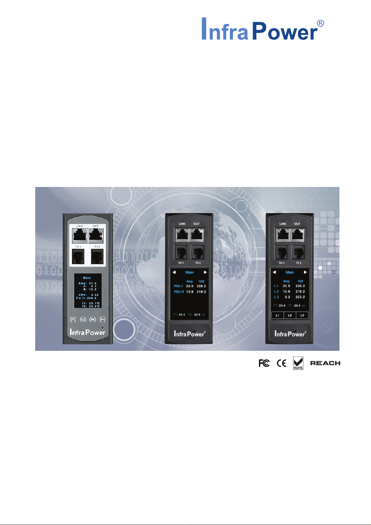
InfraPower Intelligent PDU
Inspired by Your Data Center
User Manual
Designed and manufactured by Austin Hughes
1-Phase 1-Phase
Dual Feed 3-Phase

www.austin-hughes.comUM-PPS-03-S-Q320V1
Legal Information
First English printing, September 2020
Information in this document has been carefully checked for accuracy; however, no guarantee is given to the correctness
of the contents. The information in this document is subject to change without notice. We are not liable for any injury or
loss that results from the use of this equipment.
Safety Instructions
Please read all of these instructions carefully before you use the device. Save this manual for
future reference.
■Unplug equipment before cleaning. Don’t use liquid or spray detergent; use a moist cloth.
■Keep equipment away from excessive humidity and heat. Preferably, keep it in an air-conditioned environment with
temperatures not exceeding 40º Celsius (104º Fahrenheit).
■When installing, place the equipment on a sturdy, level surface to prevent it from accidentally falling and causing dam
age to other equipment or injury to persons nearby.
■When the equipment is in an open position, do not cover, block or in any way obstruct the gap between it and the
power supply. Proper air convection is necessary to keep it from overheating.
■Arrange the equipment’s power cord in such a way that others won’t trip or fall over it.
■If you are using a power cord that didn’t ship with the equipment, ensure that it is rated for the voltage and current
labelled on the equipment’s electrical ratings label. The voltage rating on the cord should be higher than the one listed
on the equipment’s ratings label.
■Observe all precautions and warnings attached to the equipment.
■If you don’t intend on using the equipment for a long time, disconnect it from the power outlet to prevent being dam
aged by transient over-voltage.
■Keep all liquids away from the equipment to minimize the risk of accidental spillage. Liquid spilled on to the power
supply or on other hardware may cause damage, fire or electrical shock.
■Only qualified service personnel should open the chassis. Opening it yourself could damage the equipment and invali
date its warranty.
■If any part of the equipment becomes damaged or stops functioning, have it checked by qualified service personnel.
What the warranty does not cover
■Any product, on which the serial number has been defaced, modified or removed.
■Damage, deterioration or malfunction resulting from:
□Accident, misuse, neglect, fire, water, lightning, or other acts of nature, unauthorized product modification, or
failure to follow instructions supplied with the product.
□Repair or attempted repair by anyone not authorized by us.
□Any damage of the product due to shipment.
□Removal or installation of the product.
□Causes external to the product, such as electric power fluctuation or failure.
□Use of supplies or parts not meeting our specifications.
□Normal wear and tear.
□Any other causes which does not relate to a product defect.
■Removal, installation, and set-up service charges.
Regulatory Notices Federal Communications Commission (FCC)
This equipment has been tested and found to comply with the limits for a Class B digital device, pursuant to Part 15 of the
FCC rules. These limits are designed to provide reasonable protection against harmful interference in a residential instal-
lation.
Any changes or modifications made to this equipment may void the user’s authority to operate this equipment. This
equipment generates, uses, and can radiate radio frequency energy and, if not installed and used in accordance with the
instructions, may cause harmful interference to radio communications.
However, there is no guarantee that interference will not occur in a particular installation. If this equipment does cause
harmful interference to radio or television reception, which can be determined by turning the equipment offand on, the
user is encouraged to try to correct the interference by one or more of the following measures:
■Re-position or relocate the receiving antenna.
■Increase the separation between the equipment and receiver.
■Connect the equipment into an outlet on a circuit different from that to which the receiver is connected.

www.austin-hughes.comUM-PPS-03-S-Q320V1
Contents
< 1.1 > IP Dongle Specification P.1
< 1.2 > IP Dongle Installation & Meter ( PDU ) Cascade P.3
< 1.3 > Meter ( PDU ) Level Setting P.4
< 1.4 > IP Dongle Configuration P.5
< 1.5 > Remote PDU Level & ID Setting P.6
< 1.6 > PPS-03-S IP Dongle GUI P.10
< 1.7 > System P.15
< 1.8 > Network P.16
< 1.9 > Login P.17
< 1.10 > SNMP Setup P.21
< 1.11 > Notification P.26
< 1.12 > Syslog P.27
< 1.13 > IP Dongle Firmware Upgrade P.28
< 1.14 > DHCP Setting P.30
< 1.15 > Command Line Interface Access P.33
www.austin-hughes.comUM-PPS-03-S-Q320V1 P. 1
** Data refresh speed subject to number of cascaded PDU.
< 1.1 > IP Dongle Specification
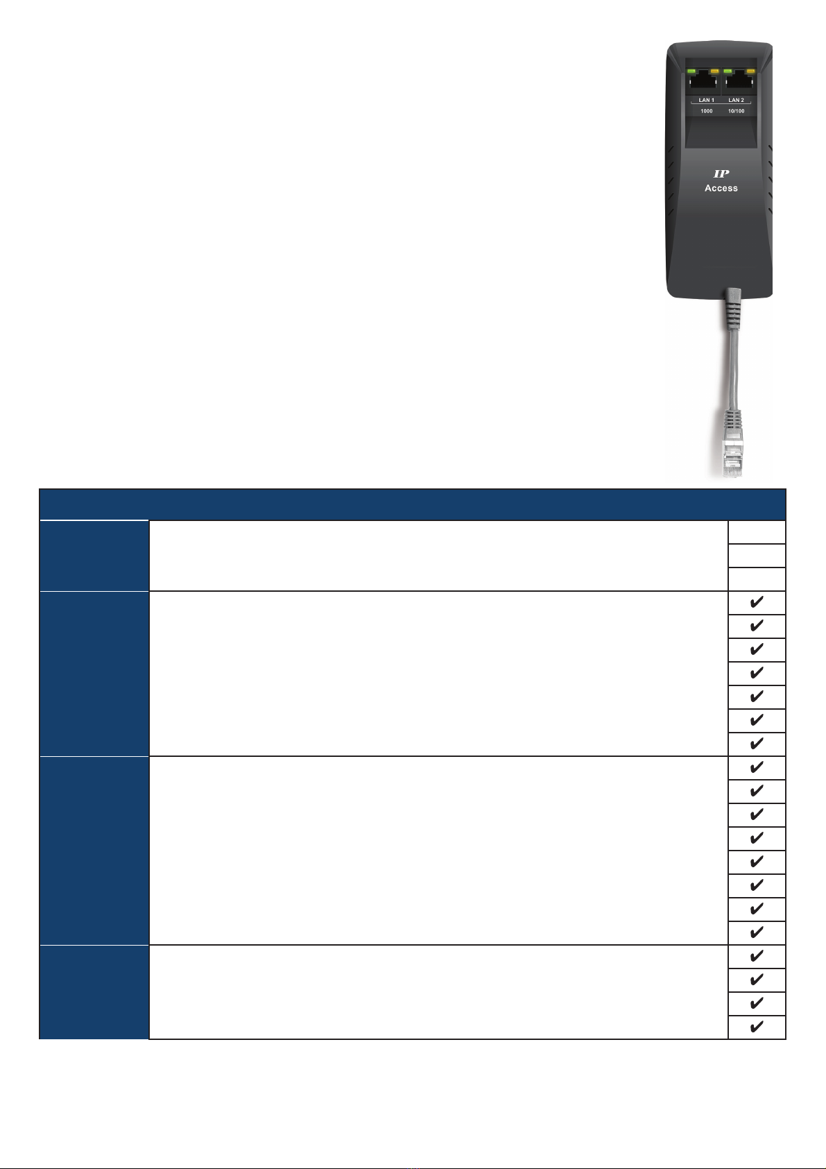
InfraPower PPS-03-S
Features
Capacity IP Dongle Group ( Just 1 for 32 PDU levels ) 1
Max PDU number per IP dongle ( IPD-03-S )** 32
Concurrent Users 1
Enhanced
Features
Outlet Level kWh & Amp Measurement
Outlet Scheduling
Energy Consumption ( kWh ) Monitoring
Apparent Power ( kVA ) Monitoring
Power Factor Measurement
Circuit Breaker ( MCB ) Monitoring
Remote level & ID setting for cascaded iPDU
Basic
Features
Aggregate Current ( Amp ) Monitoring
Individual Outlet Switch ON/OFF
Temp-Humid Monitoring
Alarm Threshold Setting
Rising Alert Threshold Setting
Door & Smoke Sensor Monitoring
Remote Access via Web
Graphic User Interface
PDU
Series
Support
All Single & Three Phase iPDU
All Single & Three Phase Dual Feed iPDU
All Single & Three Phase inline meter
All Single & Three Phase Dual Feed inline meter
IP Dongle Access to 32 PDU Levels
Patented IP Dongle provides IP remote access to the PDUs by a true
network IP address chain. Only 1 x IP dongle allows access to max. 32
PDUs in daisy chain - which is a highly efficient application for saving not
only the IP remote accessories cost, but also the true IP addresses required
on the PDU management.
Hot-Pluggable design facilitates the IP dongle installation. Simply integrate
the IP Dongle to the 1st PDU, then the entire daisy chain group can be
remote over IP. Hence, administrator can remotely access all PDUs in the
daisy chain group by one single IP via the IP Dongle.
Part no.
IPD-03-S
www.austin-hughes.comUM-PPS-03-S-Q320V1 P. 2
Dual LAN Network Failover
> Auto failover to a 2nd Ethernet-connection in the event of network interruption
> Ensuring 100% iPDU uptime reporting
Connectivity
> Access your iPDU on two independent networks or VLANs
> Auto-negotiable 10/100 BaseT Ethernet & 1000 BaseT Gigabit Ethernet ports
> Redundant network access to the connected iPDUs via IP
Enterprise Level IP Authentication
> Active Directory (AD), Lightweight Directory Access Protocol (LDAPv3 / LDAPS),
Remote Access Dial-In User Service (RADIUS) protocol, or local credential database.
> Strong passwords and granular user/user group permissions.
Remote Management
> Significantly reduce the number of Ethernet ports used in deployment by
cascading a single network connection across multiple iPDUs (up to 32)
> Simultaneous access via free management software IPM-04, web GUI & SNMP V2 / V3
> Remote level & ID setting for cascaded iPDU’s
Alerts / Alarms
> Receive alerts via SNMP, email (SMTP), and syslog when predefined thresholds are
exceeded
for both iPDU and environmental sensor events.
> Common SNMP MIBs (Management Information Base) across all iPDU families
USB WifiPort
> Optionally connect via a Wifikit (IPD-WIFI) complying with 802.11 g/n/ac
Remote Management Protocols
> HTTP(S); SSH Command Line Interface; Telnet; SMTP; IPv6/IPv4
< 1.1 > IP Dongle Specification

www.austin-hughes.comUM-PPS-03-S-Q320V1 P. 3
< 1.2 > IP Dongle Installation & Meter ( PDU ) Cascade
Wired Dual Lan
Wireless
32 x PDU for 16 x Rack
• Detachable design
• Daisy chain by Cat 5e / 6 cable
• Max. cable length 300M (984 ft)
• One IP dongle connect Max. 32 x 1-Phase & 3-Phase InfraPower PDU
IP dongle installation steps :
- slide the IP dongle on the plate above the meter
- plug the RJ-45 connector of IP dongle into the LINK port of the 1st level PDU meter
- use the CAT. 5e / 6 cable to connect IP dongle to network device
To LINK port
of 1st PDU
1st level
PDU meter
3rd level
PDU meter
2nd level
PDU meter
Cat 5e / 6 cable
Up to 20M
Cat 5e / 6 cable
Up to 20M
To LINK port
of next PDU
( Up to 32 levels )
LINK OUT
TH 1 TH 2
www.austin-hughes.comUM-PPS-03-S-Q320V1 P. 4
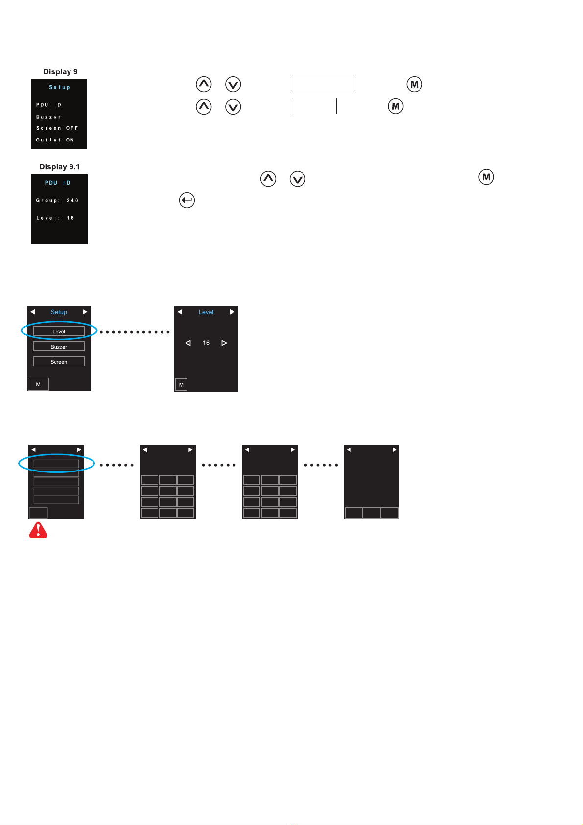
Step 3 - In display 9.1, Press the & button to select PDU level no. & press to confirm
Step 4 - Press to exit
< 1.3 > Meter ( PDU ) Level Setting
Step 1 - Press the & button to display no.9 and press to confirm
Step 2 - Press the & button to PDU ID and press to confirm
( II ) For 2.8″LCD Meter ( With touchscreen function )
( I) For 1.8″LCD Meter ( No touchscreen function )
( III ) For 2.8″LCD Meter ( With touchscreen function )
Level
16
0Cancel Enter
87 9
54 6
21 3
Level
29
0Cancel Enter
87 9
54 6
213
PDU Level
050
29
Group :
Level :
AMB
Setup
Level
Buzzer
Sensor
Screen
Outlet ON
MI
For PDU with firmware version V37 or above

www.austin-hughes.comUM-PPS-03-S-Q320V1 P. 5
< 1.4 > IP Dongle Configuration
Step 1. Prepare a notebook computer to download the IP setup utilities from the link :
http://www.austin-hughes.com/support/utilities/infrapower/IPdongleSetup.msi
Step 2. Double Click the IPDongleSetup.msi and follow the instruction to complete the installation
Step 3. Go to each first level PDU with the notebook computer & a piece of CAT. 5e / 6 cable to configure the LAN 1 Port
of the IP dongle by IP setup utilities as below. Please take the procedure for all IP dongles ONE BY ONE
After the completion of IP dongle connection, please take the following steps to configure the IP dongle :
IP dongle on 1st level PDU
To IP dongle
LAN 1 port
To notebook computer
LAN port
CAT. 5e / 6 cable
Step 4. Click “ Scan ” to search the connected IP dongle
Step 5. Enter device name in “ Name ” ( min. 4 char. / max. 16 char. ). Default is “ Name ”
Step 6. Enter device location in “ Location ” ( min. 4 char. / max. 16 char. ). Default is “ Rack_001 ”
Step 7. Enter password in “ Password ” for authentication ( min. 8 char. / max. 16 char. ) Default is “ 00000000 ”
Step 8. Enter new password in “ New password ” ( min. 8 char. / max. 16 char. )
Step 9. Re-enter new password in “ Confirm new password ”
Step 10. Change the desired “ IP address ” / “ Subnet mask ” / “ Gateway ”, then Click “ Save ” to confirm the changes
Step 11. Repeat Step 4 & Step 10 for Lan 2 Port of IP dongle
Lan 1. The default IP setting is as below:
IP address : 192.168.11.1
Subnet mask : 255.255.255.0
Gateway : 192.168.11.254
Lan 2. The default IP setting is as below:
IP address : 192.168.0.1
Subnet mask : 255.255.255.0
Gateway : 192.168.0.254
Reconnect the IP dongle with the network device
( router or hub ), after finish IP dongle configuration.
Ensure the PDU in
power ON status
The following steps show the static IP setting only. For DHCP setting, please refer to < 1.14 > DHCP Setting

www.austin-hughes.comUM-PPS-03-S-Q320V1 P. 6
InfraPower Manager PPS-03-S provides a convenient way to set the PDU level. You can set the PDU level remotely via
the IP Dongle WEBUI. Please follow the steps below to complete the Remote PDU level setting.
ONLY PDU with 2.8” LCD meter ( firmware version V37 or above ) supports this functions
You MUST have the PDU serial number onhand and know which rack the PDU is installed.
Step 1. Open Internet Explorer ( I.E. ) version 11
Step 2. Enter the configured IP Dongle address into the I.E. address bar.
Default IP address of LAN 1 is “ 192.168.11.1 “
Default IP address of LAN 2 is “ 192.168.0.1 “
Step 3. Enter the “ Login name “ and “ Password “ & Click “ Login “
Step 4. In < Status >, Click “ Search “ to start the PDU searching
< 1.5 > Remote PDU Level & ID Setting
www.austin-hughes.comUM-PPS-03-S-Q320V1 P. 7
Step 5. After the searching is completed, the following screen will display
< 1.5 > Remote PDU Level & ID Setting

www.austin-hughes.comUM-PPS-03-S-Q320V1 P. 8
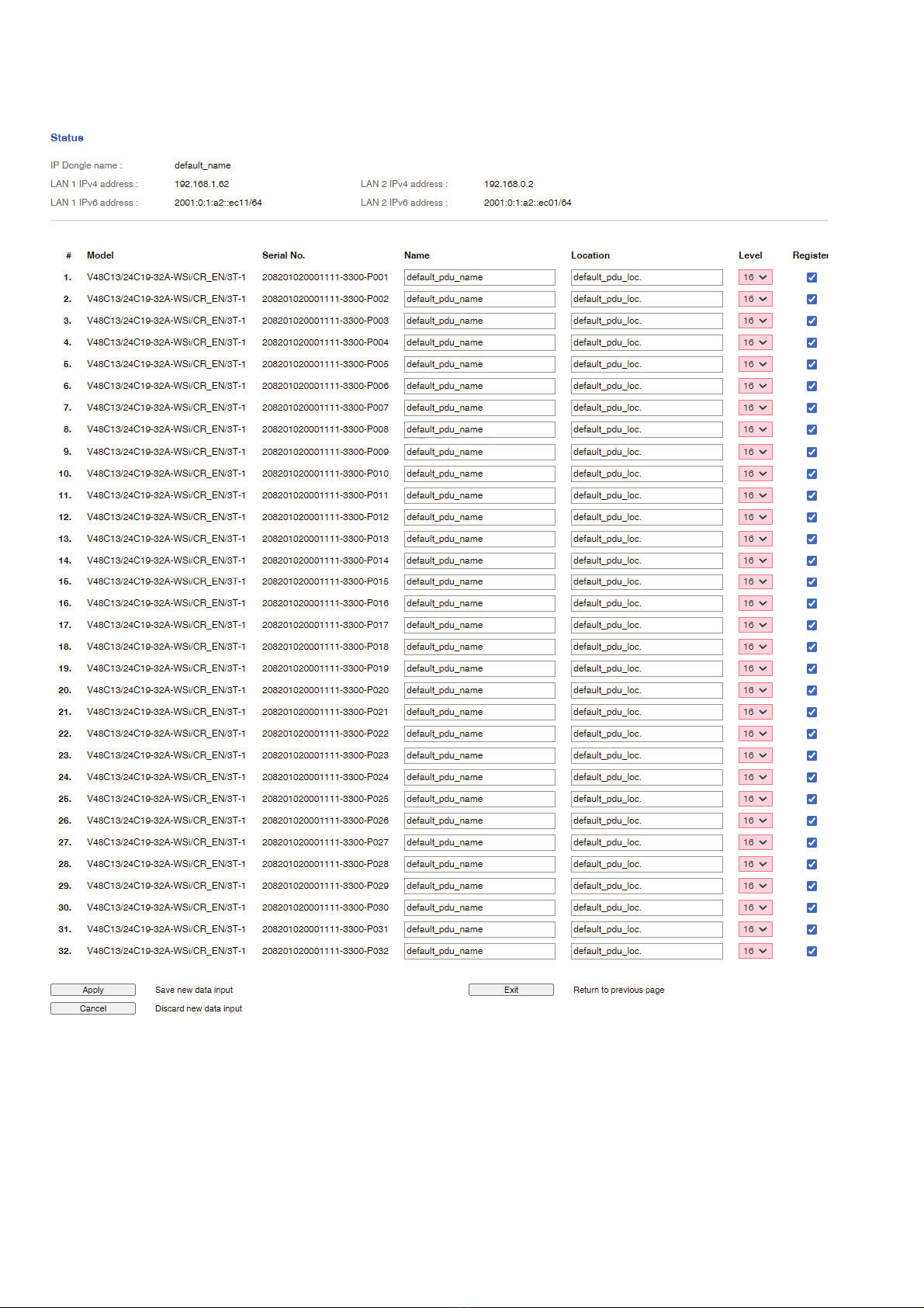
Step 6. Assign a unique “ Level “ , “ Name “ and “ Location “ to each PDU and ensure to check the register box.
Then Click “ Apply “.
< 1.5 > Remote PDU Level & ID Setting
www.austin-hughes.comUM-PPS-03-S-Q320V1 P. 9
Step 7. After the PDU level setting is complete, “ Status “ page will display the PDU with proper level.
< 1.5 > Remote PDU Level & ID Setting

www.austin-hughes.comUM-PPS-03-S-Q320V1 P.10
< 1.6 > PPS-03-S IP Dongle GUI
Each IP dongle ( IPD-03-S ) provides a FREE built-in GUI , PPS-03-S, which allows user, via a web browser, to see
PDU’s data and remotely manage the PDU over a TCP / IP Ethernet network.
Each web browser window supports only one IP dongle ( IPD-03-S ). If user installs more IP dongles,
multi windows will be required
PPS-03-S is a management software with very limited features. User can use more advanced software,
InfraPower Manager IPM-04
Step 1. Open Internet Explorer ( I.E. ), version 11.0
Step 2. Enter the configured IP dongle address into the I.E. address bar ( Please refer to < 1.4 > IP dongle configuration )
Default IP address of LAN 1 is “ 192.168.11.1 “
Default IP address of LAN 2 is “ 192.168.0.1 “
Step 3. Enter “ Login name ” , “ Password ” & Click “ Login ” ( Please refer to < 1.4 > IP dongle configuration )
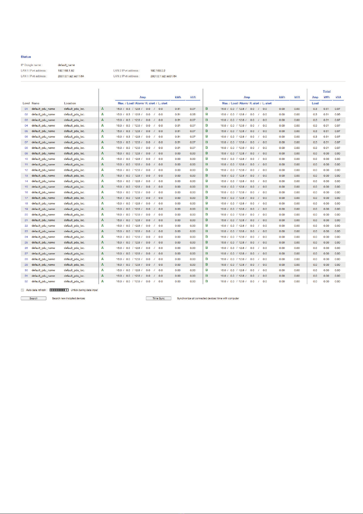
In < Status >,
- Click “ Search ” to search all new installed PDUs
- View all installed PDUs’ status
- View latest loading on each PDU’s circuits
- View aggregate current & energy consumption on each PDU
- View status & latest reading of Temp. & Humid sensors connected to each PDU
- View status of Door / Smoke sensors connected to each PDU
- Click “ Time Sync ” update all connected PDU’s real time clock from the computer logged in the IP Dongle
www.austin-hughes.comUM-PPS-03-S-Q320V1 P. 11
< 1.6 > PPS-03-S IP Dongle GUI
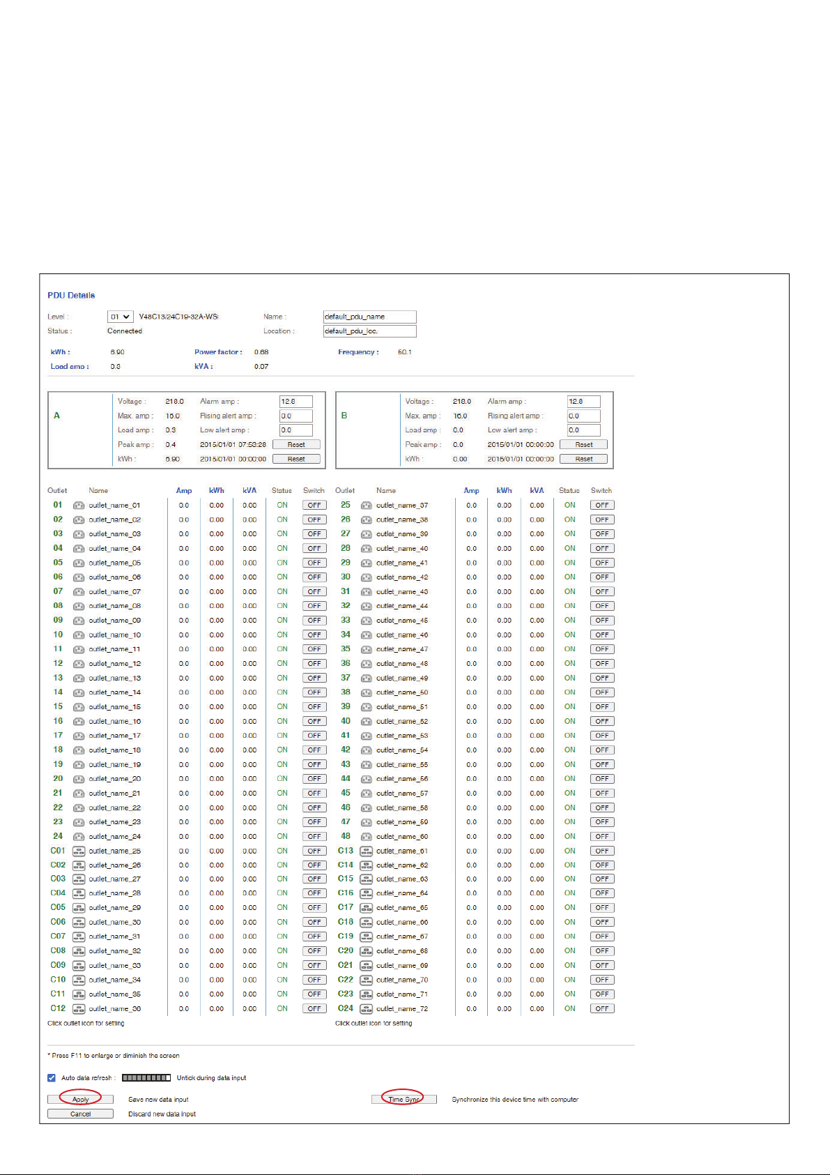
In < Details >,
- Change “ Name ” and “ Location ” of PDU & Click “ Apply ”
- Change “ Alarm amp. ” & “ Low alert amp. ” of PDU’s circuits & Click “ Apply ”
- Click “ Reset ” to reset peak amp. or kWh of PDU’s circuits
- Click “ ON / OFF ” to swich ON / OFF outlet ( Switched PDU only )
- View On / Offstatus of each PDU’s outlet
- View aggregated current on the PDU
- View latest loading & energy consumption of each PDU’s outlet
( Outlet Measurement PDU only )
- Click “ Time Sync ” update PDU’s real time clock from the computer logged in the IP Dongle
www.austin-hughes.comUM-PPS-03-S-Q320V1 P.12
< 1.6 > PPS-03-S IP Dongle GUI
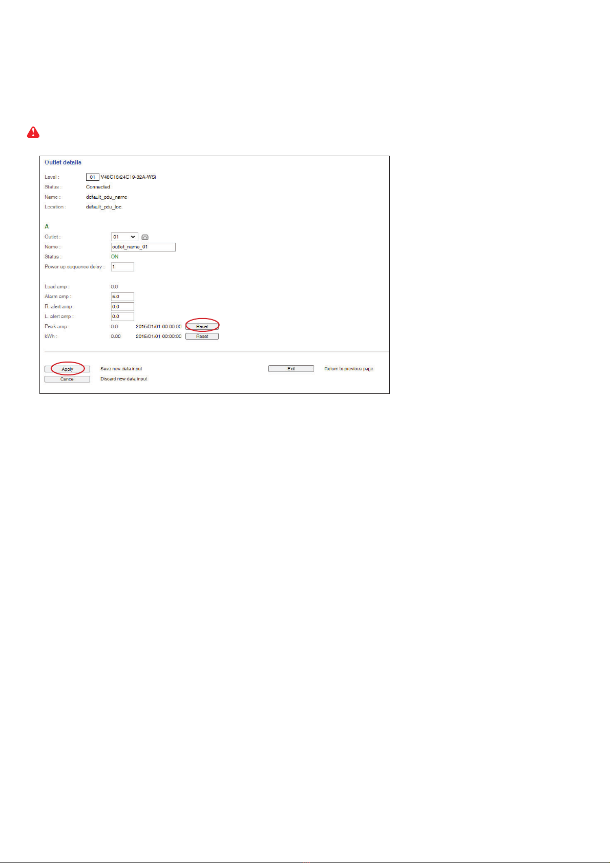
In < Outlet setting >,
- Change PDU’s outlet name
- Change “ Power up sequence delay ” of PDU’s outlet ( Switched PDU only )
- Change “ Alarm amp. ”, “ Rising Alert amp.” & “ Low alert amp. ” of PDU’s outlet
( Outlet Measurement PDU only )
Click “ Apply ” to finish the above settings
- Click “ Reset ” to reset peak amp. or kWh of PDU’s outlet ( Outlet Measurement PDU only )
www.austin-hughes.comUM-PPS-03-S-Q320V1 P.13
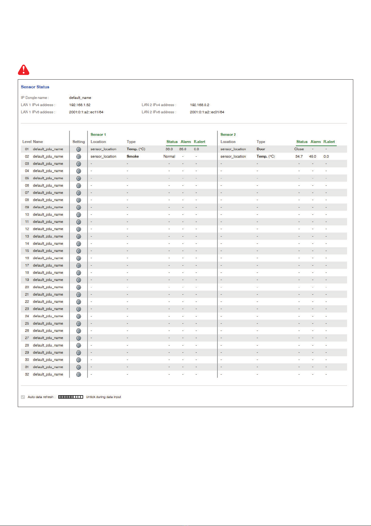
In < Sensor Status >,
- View status, location, latest reading & alarm setting of Temp. & Humid sensors.
- View status & location of Door sensor & Smoke sensor
The GUI will not show the status / reading if sensors are NOT installed & activated.
< 1.6 > PPS-03-S IP Dongle GUI
www.austin-hughes.comUM-PPS-03-S-Q320V1 P.14
< 1.6 > PPS-03-S IP Dongle GUI
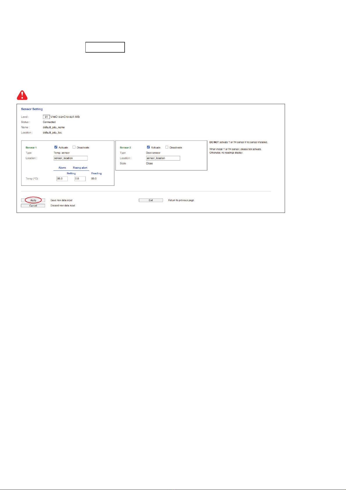
In < Sensor Setting >,
- Default Sensor setting : Deactivate
- “ Activate ” sensors ONLY when they are connected
- Change “ Location ” , “ Rising alert Setting “ & “Alarm Setting ” of Temp. & Humid sensors
- Change “ Location ” of Door sensor & Smoke sensor
If no any sensor connected, NEVER activate.
www.austin-hughes.comUM-PPS-03-S-Q320V1 P.15
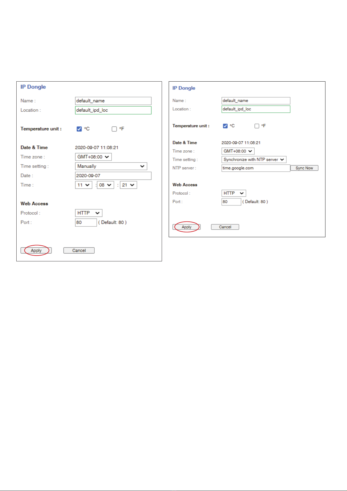
In < System >,
- Change IP dongle name & location
- Change temperature unit displayed in UI
- Set the “ Date & Time “ of the IP dongle ( by “ Manually “ or “ NTP server “ ). Default is “ Manually “
- Tick “ Force HTTPS ” to provide data transmission security. Default Web Access is “ HTTP “
- Click “ Apply ” to finish the above settings
< 1.7 > System
www.austin-hughes.comUM-PPS-03-S-Q320V1 P.16
< 1.8 > Network
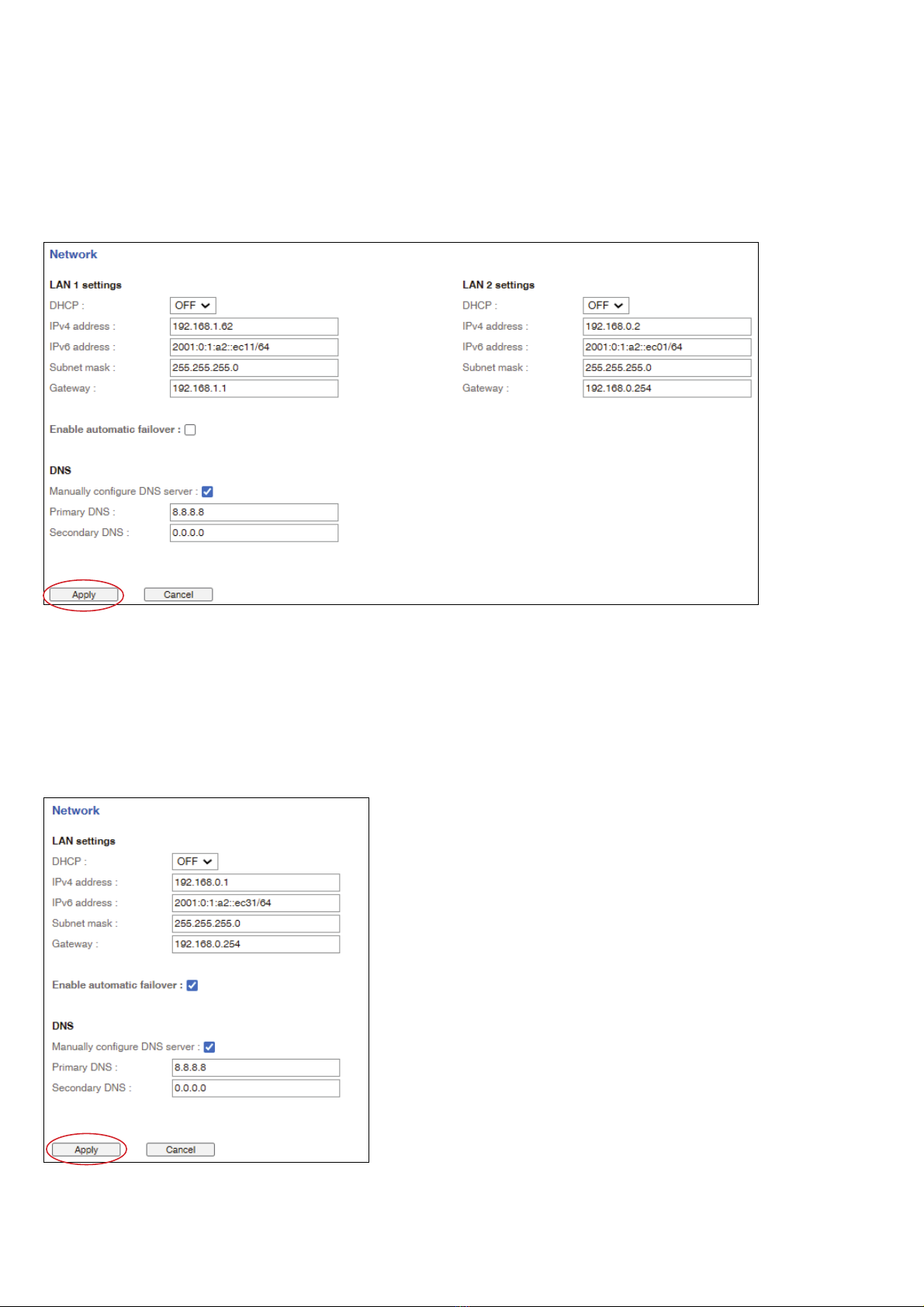
In < Network >, IP dongle can be configured to operate as Dual Lan or failover mode. Default is “ Dual Lan mode ”
Dual Lan mode :
- Enter LAN 1 “ IPv4 address ”, “ IPv6 address ”, “ Subnet mask ”, “ Gateway ”. ( For static IP setting only)
- Enter LAN 2 “ IPv4 address ”, “ IPv6 address ”, “ Subnet mask ”, “ Gateway ”. ( For static IP setting only)
- Enter the IP address of “ Primary DNS ”. Default is “ 8.8.8.8 ”
- Enter the IP address of “ Secondary DNS ”. Default is “ “0.0.0.0 ”
- Click “ Apply ” to finish the above settings
Failover mode :
- Tick “ Enable automatic failover ” to operate the failover mode
- Enter “ IPv4 address ”, “ IPv6 address ”, “ Subnet mask ”, “ Gateway ”. ( For static IP setting only)
- Enter the IP address of “ Primary DNS ”. Default is “ 8.8.8.8 ”
- Enter the IP address of “ Secondary DNS ”. Default is “ “0.0.0.0 ”
- Click “ Apply ” to finish the above settings

www.austin-hughes.comUM-PPS-03-S-Q320V1 P.17
< 1.9 > Login
In < Login >, you can login the IP dongle WEBUI by “ Local User ” or “ Domain/LDAP ” login.
( Default login : “ Local User ” )
Local User :
- Change “ Login name ” OR “ Password ”
- Re-enter password in “ Confirm password ”
- Click “ Apply ” and “ OK “ on the pop up window to make changes effective
Domain/LDAP :
- Default Join Domain is “ Disable “
- Enable “ Join Domain ” only when you want to login the IP dongle WEBUI by AD server
- Enter “ AD Server ”,“ Account Login ” & “ Password ”
- Click “ Apply ” and “ OK “ on the pop up window to make changes effective
- You can now go to “ Domain Users ” to assign access right to the “ Domain Users ” or the “ Domain Group ”
Table of contents


