TelcoBridges Tmedia TMG3200 User guide

Tmedia
System Installation Guide for
TMG3200
9010-00179-1A, Issue 2.2

The information in this document is subject to change without notice. No part of this document may be reproduced or
transmitted in any form or by any means, electronic or mechanical, for any purpose, without the express written
permission of TelcoBridges. TelcoBridges may have patents or pending patent applications, trademarks, copyrights, or
other intellectual property rights covering subject matter in this document. The furnishing of this document does not give
you license to these patents, trademarks, copyrights, or other intellectual property except as expressly provided in any
written license agreement from TelcoBridges.
The information provided in this document is intended as a guide only. For the latest detailed engineering specifications,
please contact TelcoBridges Customer Support. TelcoBridges is committed to continually improving product designs; as
a result, product specifications may be subject to change without notification.
© 2003-2009 TelcoBridges. All rights reserved.
TelcoBridges, Tmedia, TMP6400, TMG3200, TMP800, TMG800, TMS1600 Switch, Toolpack API, On a Blade, System-Blade, TB-
1+1 Solution, TB-16-E1/T1/J1, TB640-DS3, TB640-E1/T1/J1, TB640-OC3/STM-1, TB-8-E1/T1/J1, TB-IVR Mezzanine, TB-
Multi-Blade, TB-Multi-Blade Mezzanine, TB-N+1-15 Solution, TB-N+1-3 Solution, TB-StreamServer, TB-Video, TB-VoIP
Mezzanine, TM-1000 Network Probe are trademarks of Te l c o B ridges Inc. All rights reserved 2009. All other trademarks are property
of their owners. This information is subject to change without notice.
HEAD OFFICE
91 rue de la Barre, Suite 01
Boucherville, Quebec
J4B 2X6, Canada
T +1 450 655 8993
F +1 450 655 9511
Document Title: Tmedia System Installation Guide for TMG3200
Document Number: 9010-00179-1A, Issue 2.2, 2010-10-17//01:50

iii
About this Guide
This guide describes the installation and setup of the Tmedia TMG3200 telecom
platform and its connections to voice, and IP networks.
Conventions
Contact Us
If you have comments about this guide or any other TelcoBridges technical
Terminology Description
Tmedia Management
Interface
This is the interface used to configure and manage the TMG3200.
Preface

iv
Tmedia System Installation Guide for TMG3200

Table of Contents
v
Table of Contents
Chapter 1 Introduction ...................................................................................................................... 1
1.1 Installation Overview ........................................................................................................... 2
1.2 Installation Prerequisites ..................................................................................................... 3
1.3 Preventing Electrostatic Discharge Damage....................................................................... 3
1.4 Recommended Reading ..................................................................................................... 4
Chapter 2 Equipment Connections ................................................................................................... 5
2.1 Package Contents............................................................................................................... 6
2.1.1 TMG3200 Package Contents..............................................................................................6
2.2 Rack mounting the TMG3200 ............................................................................................. 7
2.2.1 Prerequisites ....................................................................................................................... 7
2.2.2 Vertical Placement of TMG3200 .........................................................................................7
2.2.3 Mounting the TMG3200 ...................................................................................................... 8
2.3 Connecting to the Tmedia Management Interface .............................................................. 9
2.3.1 Prerequisites ....................................................................................................................... 9
2.3.2 Interconnections .................................................................................................................. 9
2.4 Connecting to the VoIP Network ....................................................................................... 10
2.4.1 Prerequisites ..................................................................................................................... 10
2.4.2 Interconnections ................................................................................................................ 11
2.5 Connecting to the PSTN ................................................................................................... 12
2.5.1 Prerequisites ..................................................................................................................... 12
2.5.2 RJ48 Type Interface (T1/E1/J1) ........................................................................................13
2.5.3 SCSI Interface (T1/E1/J1) .................................................................................................15
2.5.4 Dual BNC Interface (DS3)................................................................................................. 17
2.5.5 Optical Interface (OC3/STM-1).......................................................................................... 18
2.6 Powering Up...................................................................................................................... 19
2.6.1 Prerequisites ..................................................................................................................... 19
2.6.2 Connecting to AC Power...................................................................................................19
2.6.3 Connecting to DC Power................................................................................................... 21
2.6.4 Verifying the LED Status Indications.................................................................................23
2.7 Powering Down ................................................................................................................. 24
Chapter 3 Initial System Configuration ........................................................................................... 25
3.1 Configuring the TMG3200.................................................................................................26
3.2 Setting the Time Zone....................................................................................................... 27
3.3 Configuring the Toolpack System Using the Web Portal .................................................. 27
3.4 Changing the TMG3200 Host IP ...................................................................................... 28
3.5 Changing VoIP Interface Addresses ................................................................................. 28
3.6 Changing Passwords ........................................................................................................ 28
Chapter 4 System Upgrades........................................................................................................... 29
4.1 Installing a New License ................................................................................................... 29

vi
Tmedia System Installation Guide for TMG3200
Chapter 5 Troubleshooting Tools.................................................................................................... 31
5.1 Connecting to the Serial Port of the TMG3200 ................................................................. 32
5.2 Configuring the Terminal Emulator Application................................................................. 34
5.3 Reporting a Problem .........................................................................................................35
5.4 Setup Information .............................................................................................................. 35
5.5 Tbdebug Dump Files (Mandatory).....................................................................................35
5.6 Application Logs................................................................................................................ 35
5.7 Backdoor Tools ................................................................................................................. 36
5.7.1 tbx_cli_tools_remote ......................................................................................................... 36
5.7.2 Line/Trunk Status (Tbshowls)............................................................................................ 37
5.7.3 VoIP Traffic Capture.......................................................................................................... 37
5.7.4 Wireshark (formerly called Ethereal) ................................................................................. 37
5.7.5 Tbstreamlisten................................................................................................................... 38
5.7.6 Stream Server Audio Packets to Wave File ...................................................................... 38
5.7.7 tbsigtrace Signaling Traces...............................................................................................38

1
Chapter 1 Introduction
This chapter provides an introduction to the installation and setup of a Tmedia system
using the TMG3200.
The following topics are covered:
• Installation overview
• Installation prerequisites
• Other recommended reading
2
Tmedia System Installation Guide for TMG3200
1.1 Installation Overview
The installation and setup of a TMG3200 unit, as shown in figure 1.1 on page 2, is described by a series
of chapters dealing with installation tasks in the following order:
• Rack mounting the TMG3200
• Connecting to the Tmedia Management Interface
• Connecting to the VoIP network
• Connecting to the PSTN
• Powering Up
• Initial System Configuration
• System Upgrades
• Troubleshooting
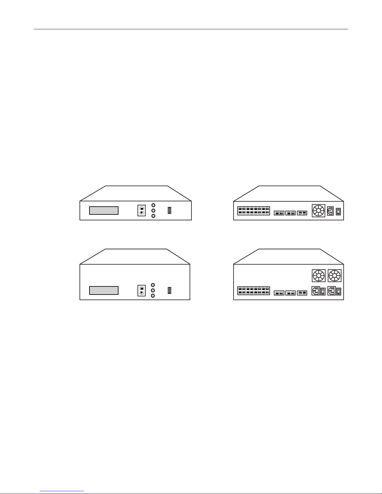
Figure 1.1 TMG3201, TMG3202, seen from front and rear.
Front Rear
Front Rear
TMG3201
TMG3202
1
9
8
16151413121110
765432
ETH VoIP TMS
12 1122
ETH VoIP TMS
12 1122
Ethernet
Console
Pwr
Reset
Function
USB
Ethernet
Console
Pwr
Reset
Function
USB
18
765432
18
765432
916151413121110

Introduction
3
1.2 Installation Prerequisites
For the TMG3200 system installation to proceed without interruption, it is important that you verify that
you have on hand all of the necessary materials. Prior to beginning the installation, you should have
prepared for the following:
• Adequate space for the installation of your TMG3200. Consider that you will need to mount the
TMG3200 on a 19” customer-provided equipment rack.
• Adequate power supply and power connections. To guarantee an uninterrupted supply, the
TMG3200 must be powered by a dedicated power source. Consider that the TMG3200 will require
one to two power connections. TMG3200s (other than 2U DC-powered units) are not shipped with
power cords; therefore, you will need to plan for your power cable requirements.
• To run your telecom applications on the TMG3200, you will need to have purchased an adequate
number of licenses for the features that you will use.
1.3 Preventing Electrostatic Discharge Damage
Electrostatic discharge (ESD) can damage equipment and impair electrical circuitry. It may occur if
electronic printed circuit cards are improperly handled and may cause complete or intermittent failure.
Attention Always follow ESD prevention procedures when removing and replacing modules:
• Ensure that the TelcoBridges TMG3200 is electrically connected to earth ground.
• Wear an ESD-preventive wrist strap and ensure that it makes good contact with your
skin. Connect the wrist strap clip to an unpainted surface of the TMG3200 or the
grounded equipment rack in order to channel away all ESD voltage safely to ground.
To guard against ESD damage and shocks, the wrist strap and cord must be in proper
working condition.
• If no wrist strap is available, and you must work with the TMG3200, ground yourself by
touching a metal part of the chassis.

4
Tmedia System Installation Guide for TMG3200
1.4 Recommended Reading
This document assumes that you are well versed in the installation of the TelcoBridges TMG3200 and
have been trained to work with the equipment. If you have any technical questions, please contact
Other documents exploring various aspects of the Tmedia system are available on the TelcoBridges TB
Wiki at: http://docs.telcobridges.com/mediawiki/index.php/Main_Page

5
Chapter 2 Equipment Connections
This chapter provides the connection procedures for the TMG3200 as follows:
• Rack mounting the TMG3200
• Connecting to the Tmedia management interface
• Connecting to a PSTN Network
• Connecting to an IP network
• Connecting Power
• Verifying LED Status

6
Tmedia System Installation Guide for TMG3200
2.1 Package Contents
You will have received one TMG3200. The TMG3200 is the telecom platform on which you will run your
telecom applications.
2.1.1 TMG3200 Package Contents
In the TMG3200 box, you will find:
• One TMG3200
• One set of mounting brackets with screws. These are used for the mounting of a TMG3200 on a
19” rack.
• One DB-9 to RJ-45 adapter. Allows you to interface the serial port of your computer with the RJ-45
console port of the TMG3200.
• SCSI cables and patch panels. This is optional and only provided if the PSTN interface on your
TMG3200 features SCSI connectors.
• Three CAT5 Ethernet straight cables (male-male), three meters in length.
• One warranty sheet
• One packing slip
• One TMG3200 Quick Installation guide (a 1-page sheet that provides a pictorial view of equipment
setup).
• For 2U DC units, two DC power cables are provided.
Not included with the TMG3200:
• No power cords are supplied for the AC units. Only in the case of the 2U DC unit with redundant DC
supplies, are two power cables supplied.
• A 19” equipment rack. You will use a standard 19” wide equipment rack to install the TMG3200.
Equipment Connections
7
2.2 Rack mounting the TMG3200
The TMG3200 is mounted on a customer provided equipment rack using the mounting hardware
packaged in the box.
2.2.1 Prerequisites
To rack mount the TMG3200, you will need:
• One 19” customer provided equipment racks. The rack must be solidly anchored to the floor with
appropriate support at the top of the racks.
• Climate controlled room: 0 to +50 Celsius, 0 to 95% non-condensing humidity.
2.2.2 Vertical Placement of TMG3200
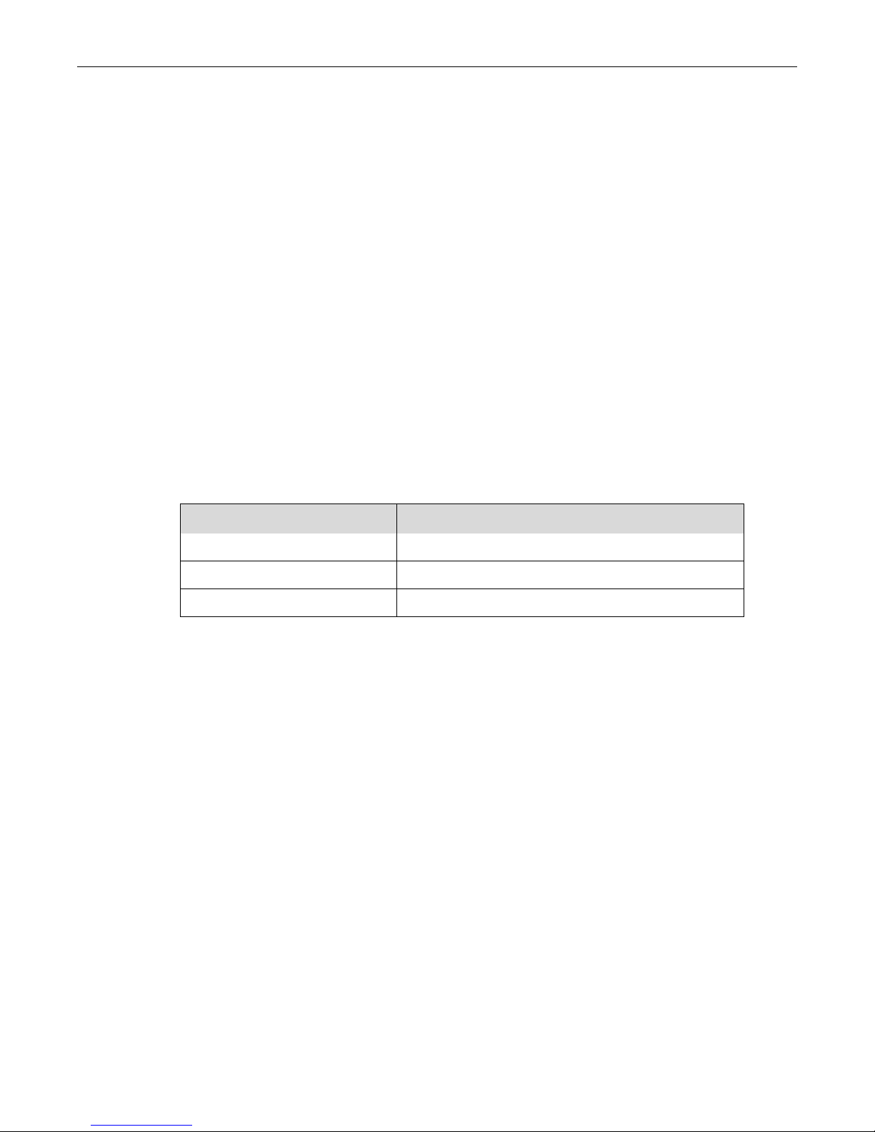
The TMG3200s are housed in either a 1U or 2 U chassis, as tabulated in table 2.1 on page 7. It is
important that you provide for enough room on the equipment rack to allow for the installation of the
TMG3200. Consider the available space on your equipment rack and the height of the TMG3200. Due
to the rear-exhaust heat vents and the efficient heat dissipation design, there is no need to leave any
physical vertical space above or below the placement of the TMG3200 on the equipment rack.
Table 2.1 TMG3200 Physical Height
Tmedia Model Number Vertical Height
TMG3201 1U
TMG3202 2U
Patch Panelsa
a. TMG3200s configured with a 32 to 64 T1/E1 TDM module require one patch panel for each 32 E1/T1 line grouping.
1U
8
Tmedia System Installation Guide for TMG3200
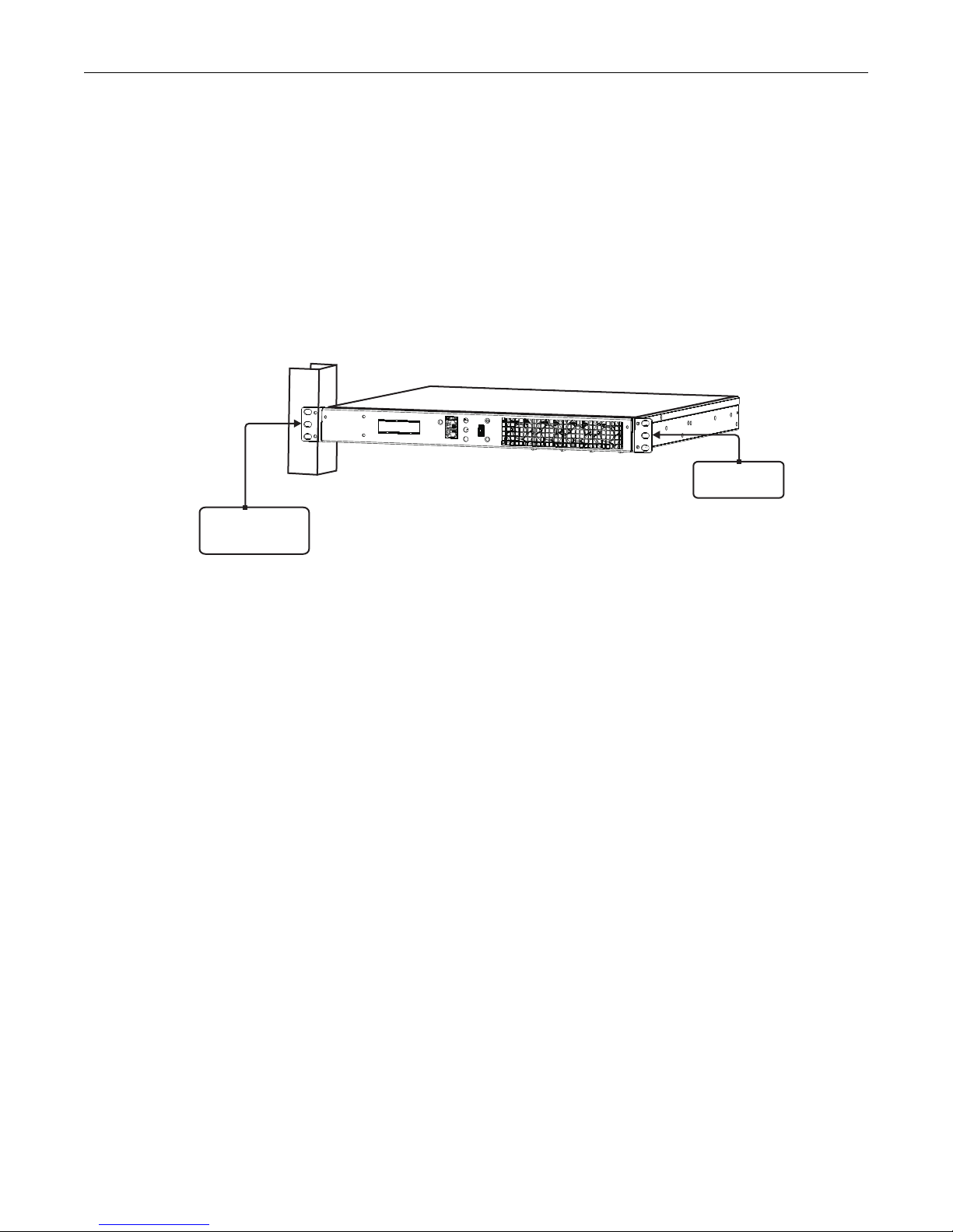
2.2.3 Mounting the TMG3200
The TMG3200 is mounted on the 19” equipment rack using the angle brackets and screws provided in
the box. To mount the hardware, proceed as follows:
To mount the TMG3200 proceed as follows:
1. Using two metal screws, attach one angle bracket to the front, left-hand side of the TMG3200 when
viewed from the front, as shown in figure 2.1 on page 8. Repeat the same for the angle bracket on
the right-hand side.
2. Start mounting equipment at the top-most position of the rack, keeping in mind the space required
on the equipment rack as described in Section 2.2.2 “Vertical Placement of TMG3200” on page 7.
Figure 2.1 Mounting the TMG3200
Attach Bracket
to Tmedia Unit
Attach Tmedia
Unit to Equipment
Rack
Equipment Connections
9
2.3 Connecting to the Tmedia Management Interface
The Tmedia Management Interface enables administrators to perform management tasks on the
TMG3200.
2.3.1 Prerequisites
To communicate with the Tmedia Management Interface for a TMG3200, the following is needed:
• One CAT5 Ethernet cable with RJ45 male-male terminations.
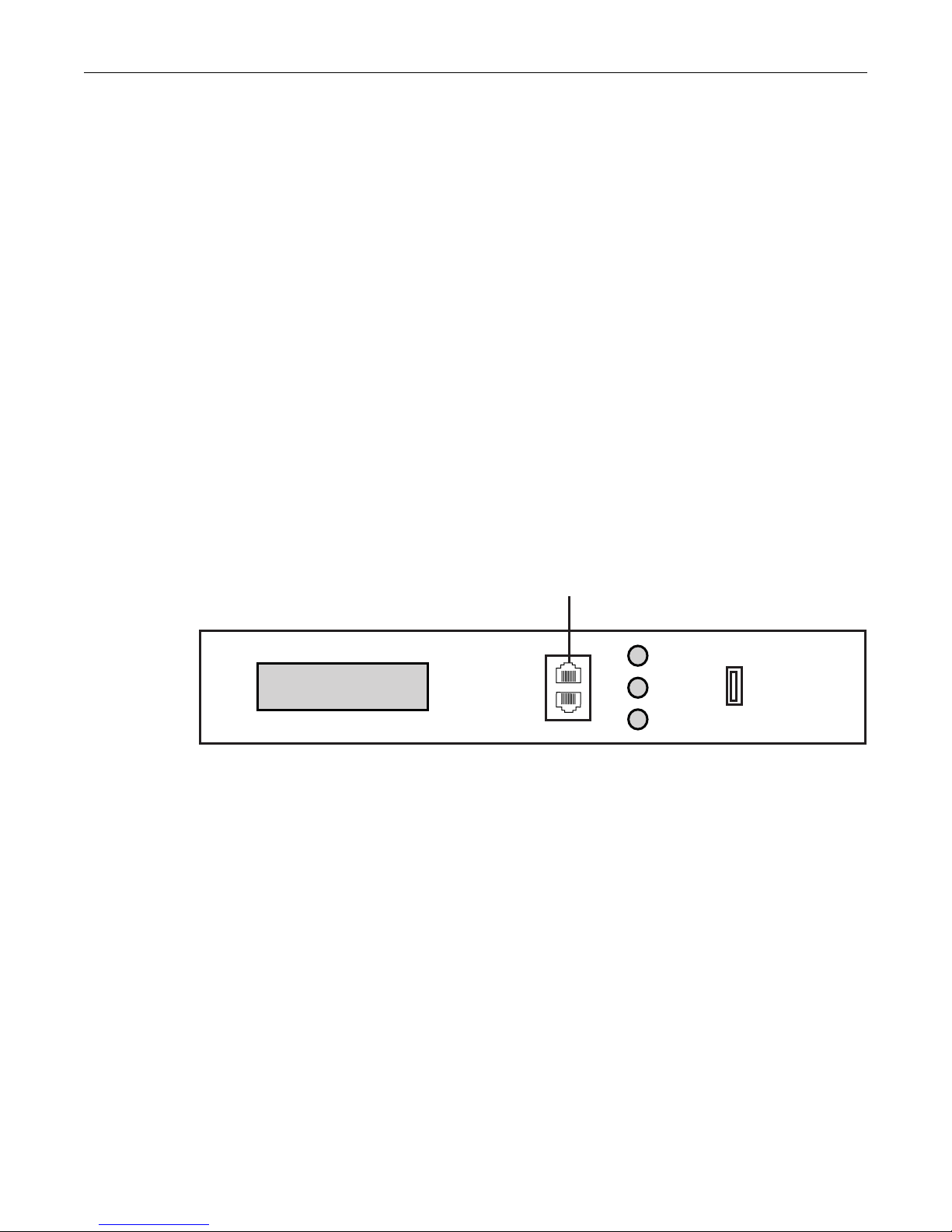
2.3.2 Interconnections
The TMG3200 provides a Tmedia Management Interface, using one Gigabit Ethernet network link, as
shown in figure 2.2 on page 9.
To communicate with the Tmedia Management Interface:
1. Connect the supplied CAT5 Ethernet cable to the port labelled “Ethernet” at the front of the
TMG3200.
Figure 2.2 Tmedia Management Interface
Ethernet
Console
Pwr
Reset
Function
USB
Management Interface
TMG3200 (front)

10
Tmedia System Installation Guide for TMG3200
2.4 Connecting to the VoIP Network
The TMG3200 features dual 100 Mbps/1000 Mbps ports for connection to different VoIP networks.
Should one of the IP networks fail, the TMG3200 will continue to handle VoIP traffic using the alternate
network.
Note: Certain configurations of the TMG3200 will exceed 100 Mbps, therefore
1000 Mbps is recommended.
2.4.1 Prerequisites
To connect the TMG3200 to the VoIP network, you will need:
• Gigabit Ethernet switch. A second one is required to support redundancy of the VoIP interface.
• One CAT5 Ethernet cable with RJ45 male-male terminations for each TMG3200.
• If your system has access to a second VoIP network, you can connect it to a second VoIP interface
of the TMG3200 with an RJ45 (male-male) CAT5 Ethernet cable.
Equipment Connections
11
2.4.2 Interconnections
The TMG3200 is connected to the VoIP network by one or optionally two Ethernet GigE network links,
as shown in figure 2.3 on page 11.
To connect the TMG3200 to the VoIP network:
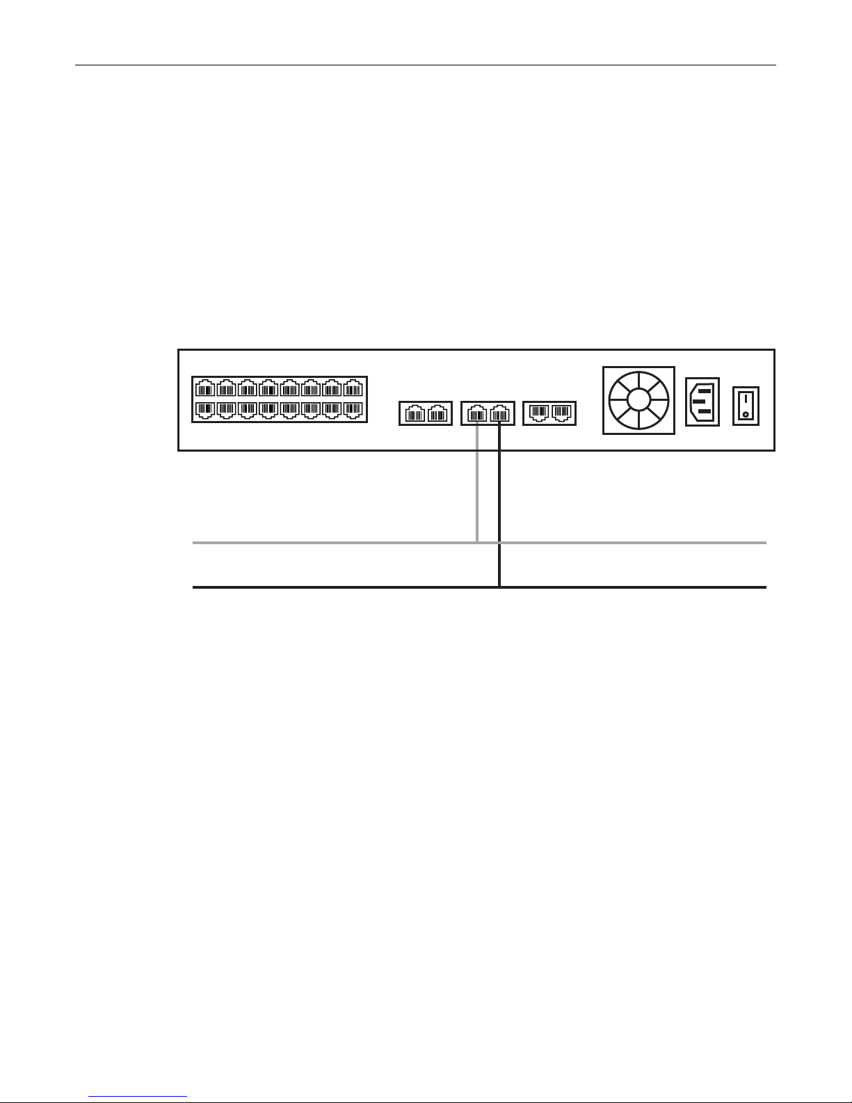
1. Connect a CAT5 Ethernet cable to VoIP1 at the rear of the TMG3200. Connect the other end of the
same CAT5 cable to the Gigabit Ethernet switch.
2. If your system employs a second Gigabit Ethernet switch for redundancy, connect a second CAT5
Ethernet cable to VoIP2 at the rear of the TMG3200. Connect the other end of the same CAT5
cable to the second Gigabit Ethernet switch.
Figure 2.3 Connecting to the VoIP Network
TMG3200
VoIP Network 1
VoIP Network 2
ETH VoIP TMS
1211 2
2
1
9
8
16151413121110
765432

12
Tmedia System Installation Guide for TMG3200
2.5 Connecting to the PSTN
The TMG3200 features a variety of interfaces to the PSTN network. Each TMG3200 that makes
connection with the PSTN will feature a PSTN interface.
2.5.1 Prerequisites
To connect the TMG3200 to the PSTN network, you must comply with one of the following:
• Your TMG3200 features 16 modular 8-conductor RJ48 type jacks for connection to T1/E1/J1 lines.
You will need one cable for each (T1/E1/J1) interface on the TMG3200. If you are making your own
cables, refer to figure 2.5 on page 14 for crossover or straight cable wiring connections.
• Your TMG3200 features SCSI connectors for connection to T1/E1/J1 lines. You will require one
patch panel for each 32 line grouping of T1/E1/J1 line interfaces on the TMG3200.
• Your TMG3200 features BNC connectors for connection to DS3 lines. You will require two coaxial
cables for each DS3 interface.
• Your TMG3200 features electrical or optical STM 1connectors. You will require two fibre optic
cables for the STM 1 interface of the TMG3200.
Equipment Connections
13
2.5.2 RJ48 Type Interface (T1/E1/J1)
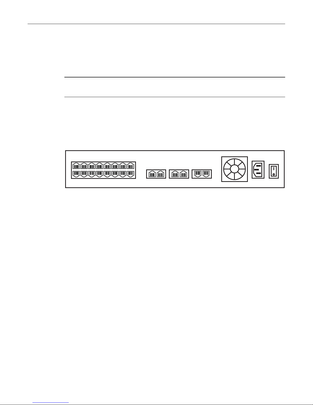
A TMG3200 with 16 RJ48 type ports enables the connection to T1/E1/J1 lines. The termination
impedance is set at 100 ohms for T1 lines and 120 ohms for E1 lines. It is possible to connect an
external balun in order to convert to 75 ohms. See figure 2.4 on page 13. If you are making your own
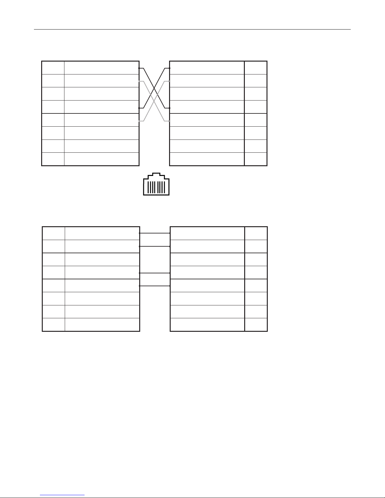
cables, refer to figure 2.5 on page 14 for crossover or straight cable wiring connections.
Note All ports may not be active. T1/E1/J1 ports are activated by software license; the number
of active ports depends on the licenses purchased.
To connect the TMG3200 (RJ48 type) to the PSTN:
1. Start with port 1 located at the top and left-most position. Connect one cable between this port and
the T1/E1/J1 line (figure 2.4 on page 13).
2. Repeat step 1, using the next available port.
Figure 2.4 16-Port Interface to the PSTN
ETH VoIP TMS
1211 22
1
9
8
16151413121110
765432
14
Tmedia System Installation Guide for TMG3200
Figure 2.5 RJ48 Wiring Schematic
1
RX/Ring/-
2
RX/Tip/+
3
Not Connected
4
TX/Ring/-
5
TX/Tip/+
6
Not Connected
7
Not Connected
8
Not Connected
RJ 48 (T1/E1/J1) Wiring Schematic: Crossover Cable
18
RX/Ring/-
1
RX/Tip/+
2
Not Connected
3
TX/Ring/-
4
TX/Tip/+
5
Not Connected
6
Not Connected
7
Not Connected
8
1
RX/Ring/-
2
RX/Tip/+
3
Not Connected
4
TX/Ring/-
5
TX/Tip/+
6
Not Connected
7
Not Connected
8
Not Connected
RJ 48 (T1/E1/J1) Wiring Schematic: Straight Cable
RX/Ring/-
1
RX/Tip/+
2
Not Connected
3
TX/Ring/-
4
TX/Tip/+
5
Not Connected
6
Not Connected
7
Not Connected
8
Other manuals for Tmedia TMG3200
2
Table of contents


