UMX-MC6 Switching card with 2 input channels
and 6 output zones
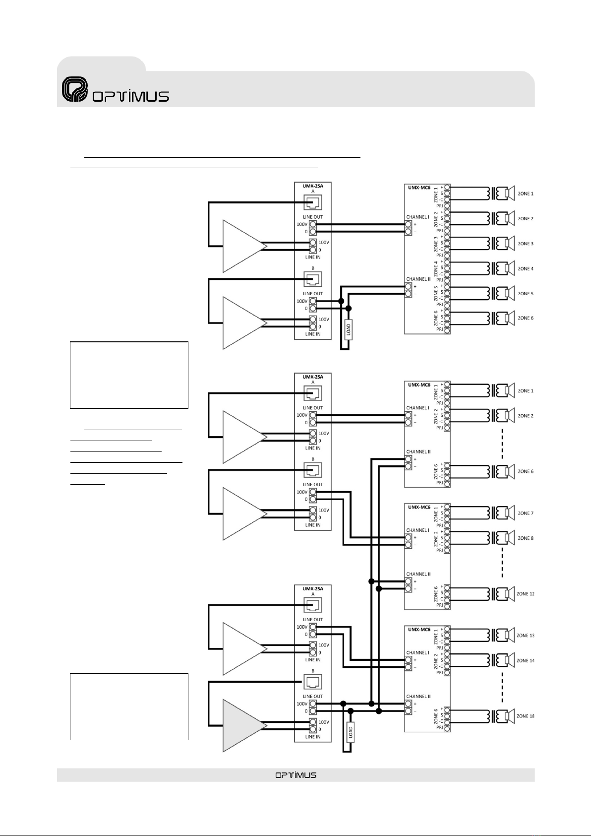
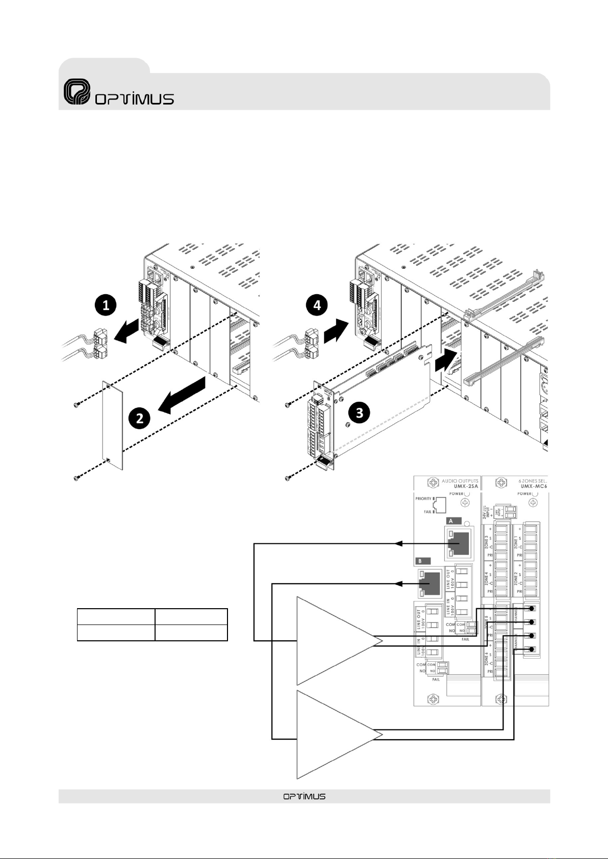
4.2. Connection of channels I and II; installation with surveillance
In the case that the surveillance is enabled, the system will
report the failures on each zone of loudspeaker lines and
also of each amplifier. Automatically the back-up function
is activated.
While both amplifiers are working without error, the A
amplifier is used for music purposes and B amplifier is used
for paging purposes.
When a message is sent to a zone, the music stops in that
zone and the message sounds. In the rest of the zones, the
music remains.
When the amplifier B (paging) fails, the amplifier A
(music/backup) also performs the paging amplifier
functions. In this case, when a message is sent, the music
stops in all zones and the message sounds in the selected
zone. Once the message finishes, the music returns for all
zones.
* An external load of value
between 1K8 and 2K2 and
power rate greater than 7W
should be connected in order
to monitor the amplifier B.
A
B
In the case that the surveillance is enabled, the system will
report the failures on each zone of loudspeaker lines and
also of each amplifier. Automatically the back-up function
is activated.
While both amplifiers are working without error, the A
amplifier is used for music and paging purposes.
When a message is sent to a zone, the music stops for all
zones and the message sounds only in the selected zone.
Once the message finishes, the music returns for all zones.
If an amplifier fails, the back-up amplifier takes its place, so
both the music and the announcements will remain
operative in zones corresponding to the failed amplifier
This option allows to assign a single backup amplifier to
multiple amplifiers using various UMX-MC6 cards.