Infrasonic QUARTET User manual
www.infra-sonic.com

2
INDEX
1. Introduction ..........................................................................................................3
1.1. The cutting edge technology ...............................................................................3
1.2. What’s in the box ..............................................................................................4
1.3. Key features .....................................................................................................5
2. Description of QUARTET ........................................................................................6
2.1. PCI Card ..........................................................................................................6
2.2. External I/O cable .............................................................................................7
3. Hardware Installation ...........................................................................................8
3.1. Minimum system requirement.............................................................................8
3.2. Preparation for Hardware Installation...................................................................8
3.3. PCI Card Installation..........................................................................................8
4. Driver software installation .................................................................................10
5. The control panel.................................................................................................11
5.1. Control Mixer .................................................................................................. 12
5.2. Configuration section ....................................................................................... 14
6. FREE Mixer ..........................................................................................................15
6.1. Matrix Window ................................................................................................ 16
6.2. How to use FREE Mixer .................................................................................... 16
6.3. Examples of usage .......................................................................................... 17
6.4. Practical examples........................................................................................... 17
6.5. Balanced link and FREE Mixer ........................................................................... 20
7. Application setups ...............................................................................................21
7.1. Cubase and Nuendo......................................................................................... 21
7.2. Samplitude Device Setup ................................................................................. 21
7.3. SONAR........................................................................................................... 22
7.4. TRAKTOR 3 LE ................................................................................................ 23
7.5. Samplitude SE No. 9........................................................................................ 23
8. Block Diagram .....................................................................................................25
9. Hardware Specifications ......................................................................................26
END USER WARRANTY .............................................................................................27
IQM110822001
* All specifications are subject to change without prior notice

3
1. Introduction
INFRASONIC QUARTET is a multi-purpose pro audio interface card using stable PCI bus
technology. PCI interface cards run faster and are more stable than Hot-plug systems such
as USB and FireWire. QUARTET is suitable for providing high quality, multi-function, sound
editing for your home studio and at a good price.
QUARTET has better performing analog I/Os than other cards in its class. It supports 192
kHz ADC sample-rate with Full 24-bit recording. The high-quality AD/DA converter has
115dB S/N ratio and the high-end components in the analog circuit improve dynamic range
by 10dB.
Other features include MIC preamp, direct instrument input, MIDI I/O, coaxial I/O, word
clock I/O and dual headphone amplifiers. QUARTET will satisfy a user as professional gear in
feature, performance and convenience.
1.1. The cutting edge technology
US-PSB class I (Ultra Stable Power Supply Block)
The QUARTET is equipped with ‘US-PSB class I’ OP-AMP based discrete circuits instead of
a general regulator type IC.
US-PSB reduces output noise as well as reducing power noise by more than 10dB.
Mass storage capacitors and protection circuits effectively deal with electronic shock and
noise. It can be monitored in detail by the powerful drivers and OP-AMP circuitry.
It results a very stable power flow.
In addition, it has the function of slowly rising voltage, called “Slow slope ON”. This
protects monitor speakers and headphones from being damaged by ‘pop-noise’ when you
turn on your PC.
IS (InfraSonic) Microphone Preamplifier
IS MIC Preamplifier - a low noise transistor buffer, high quality microphone preamplifier
(E.I.N: Equivalent input noise -127dBu).
Not only is the value of E.I.N 20dB lower, but its quality of CMRR and frequency response
is better than other similar grade products.
It delivers professional recording studio grade audio quality.
PAD / GAIN jumpers allow the usage of many microphone types (from the condenser
microphones to low leveled dynamic microphones).
Like a professional MIC preamplifier, QUARTET supports the Low-cut function and +48V
phantom power.
Noise Guard Bracket
Generally, a lot of high frequency digital noise exists inside of a computer, especially if
you have more PCI cards close to one another.
Noise Guard Bracket is designed to protect QUARTET from electronic noise that the
computer and other PCI/video cards generate.
4
IS (InfraSonic) Line / Headphone Drivers
In the analog output circuit of QUARTET there is no need to classify between line output
and headphone output.
The output jacks automatically know the difference between stereo headphone jacks or
line outputs to your speakers or mixer.
A noise shaping filter and high grade film-capacitors in the output ports can block
“Quantization noise” in the DACs (Digital Audio Converters) perfectly.
With a wide frequency response it plays back sound as close to reality as possible.
Virtual I/O Channels
QUARTET is equipped with 4X4 physical channels. It also supports virtual extended 4X4
channels, which can be easily mapped through FREE mixer.
FREE (Flexible Routing Enhanced Engine) Mixer
With FREE mixer, it is possible to connect to every part of the hardware in/outputs, WDM
and ASIO drivers to themselves.
You can use them altogether to mix and route more freely.
Depending on your setup, it can be used as input monitor, sub mixer, connection between
drivers or any purpose you want.
V-Balanced I/O
Use Quartet as balanced 2 In / 2 Out interface instead of unbalanced 4 In / 4 Out. The IO
type selection is available through a simple click on the “VB IN”and / or “VB OUT”
buttons in the control panel of the driver. V-balanced Driver provides not only a simple
alternative IO type, but also provides easy control and flexibility over the number of IO
channels. It can be changed to 4 unbalanced inputs X 2 balanced outputs, 2 balanced
inputs X 4 unbalanced-outputs or 2 balanced in and outputs. You have the freedom of
choice for any of your system setups.
1.2. What’s in the box
QUARTET PCI card
External I/O cable
TRAKTOR 3 LE Bundle CD (Optional)
Magix Samplitude 9 SE installation CD (Optional)
Driver installation CD
Four screws and isolators for the noise guard bracket
This Manual

5
1.3. Key Features
Total 4 x 4 channel 24-bit/192kHz Audio Interface
PCI Local Bus Spec. 2.2 compliant –designed to suit +3.3V and/or +5V PCI slot
Precision low noise microphone preamplifier with +48V phantom and low cut
Built-in selectable direct instrument input
Built-in high quality dual headphone amplifiers
High quality Audio-Converters and expert analog technology
ADC : 113dB dynamic range (up to 24-bit/192kHz)
DAC : 115dB dynamic range (up to 24-bit/192kHz)
Hardware mixer for direct monitoring
Cross-Latch type 1/4" TRS stereo jack for reliable analog I/O
2 Stereo unbalanced or 1 balanced analog inputs (1/4" TRS Stereo, -10dBV)
2 Stereo unbalanced or 1 balanced analog outputs (1/4 TRS Stereo, -10dBV)
RCA connector for coaxial I/O (up to 192kHz)
Shutter type optical output jack for S/PDIF output
Supports AC-3/DTS pass-through
Support for Windows® XP, VISTA, Windows 7 (32/64bit)
Supports ASIO2.2, WDM, DirectSound
Word Clock I/O : Fs / 256*Fs, BNC Connector
16 channels MIDI I/O
FREE Mixer
Virtual I/O channels
V-Balanced I/O
6
2. Description of QUARTET
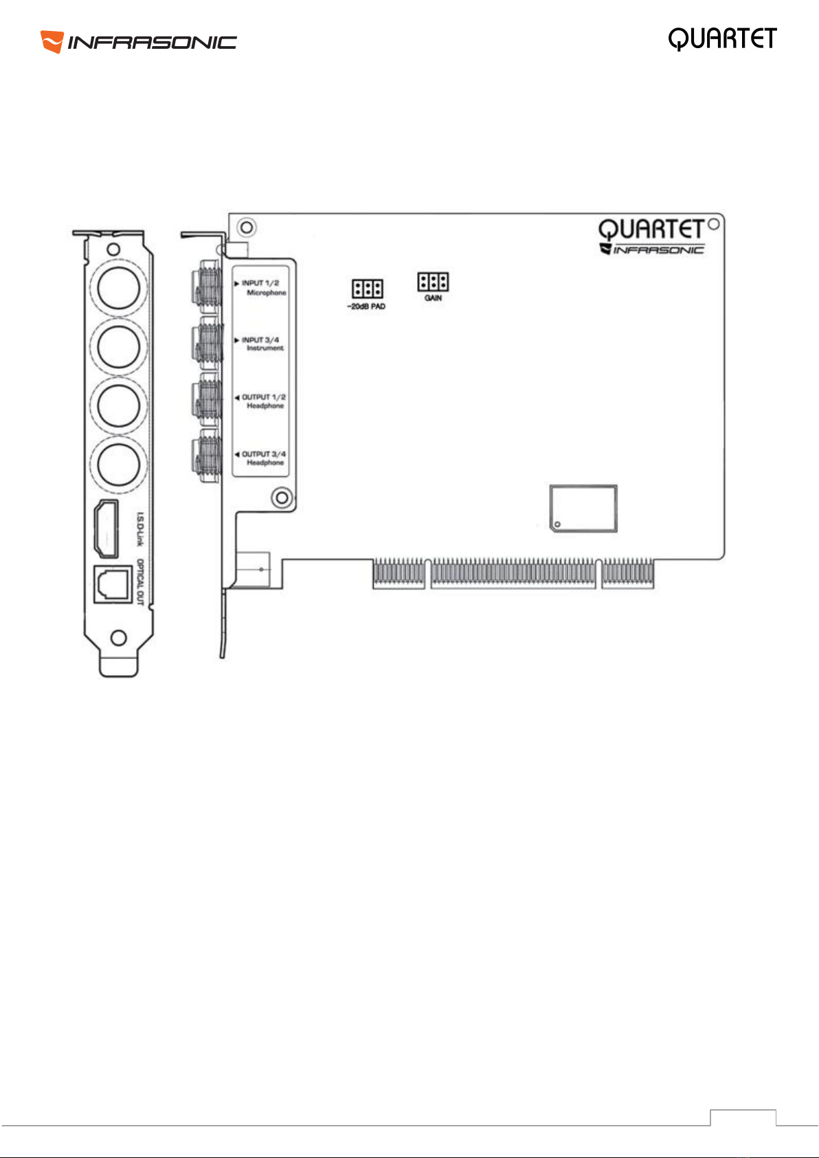
2.1. PCI Card
+48V phantom power LED: Lights up, if the phantom power is in use.
INPUT 1/2 & Microphone connector:
This connector is designed for both analog stereo Line inputs and Microphone input. Connect
your dynamic or condenser Microphone to this Balanced 1/4” connector.
INPUT 3/4 & Instrument connector:
This connector is designed for both analog stereo Line inputs and Instrument input. Connect
your electric guitar or bass guitar to this unbalanced 1/4” connector. Only unbalanced 1/4”
phone jack connection is available for this setting.
OUTPUT 1/2, 3/4: These connectors are designed for stereo Line and Dual headphone
outputs.
I.S.D-Link (INFRASONIC Digital Link): Connect the External I/O cable to this port.
Optical out: Allows you to transfer QUARTET’s audio data digitally, directly to devices like a
DAT, MD, CD-recorder with digital input. The maximum sample rate for the optical output is
96 kHz.
7
PAD jumper: Generally, the function of PAD jumper is used with professional microphone
pre-amplifications. When using high-sensitivity condenser microphones or recording a loud
drum sound or doing proximity recording, PAD jumper can be set to allow extended input
level by -20dB. This way QUARTET provides +20 dB headroom for higher input levels and
results a clipping and distortion free recording.
PAD OFF (Default) PAD ON
MIC GAIN jumper: This jumper allows you to select the amount of input gain. If you set
the correct jumper position according to recording situations, you can achieve noiseless
sound and better quality than you think.
+20dB
+40dB (Default)
+60dB
Jumper setting for high-sensitivity
condenser microphones
Jumper setting for
dynamic microphones
Jumper setting for recording
sound sources in the distance
CAUTION
Before connecting the condenser microphone to QUARTET, please make sure, that the +48V
phantom power is disabled. Before powering the phantom power on/off, also please make
sure that the connection is firm and secure. If you do not respect this caution, electric shock
may harm your microphone and QUARTET.
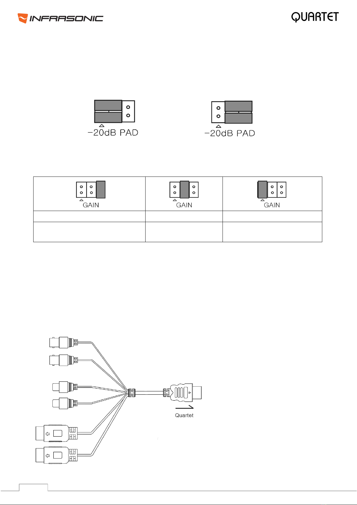
2.2. External I/O cable
Word Clock I/O: This port is for
the matching Word Clock with
other audio cards/devices. You
can set Word Clock between other
pro audio device and QUARTET via
this port.
Digital S/PDIF Coaxial I/O:
Connect digital devices such as
decoders. This connector allows
you to transfer QUARTET’s audio
data digitally, directly to devices
like a DAT, MD, CD-recorder with
digital input. This coaxial I/O port
fully supports 192 kHz.
MIDI I/O: QUARTET provides 16
midi channels I/Os.
8
3. Hardware Installation
3.1. Minimum system requirements
Intel Pentium 4 / AMD Athlon or equivalent and compatible CPU
Motherboard with chipset supporting the Intel Pentium 4/AMD Athlon
1GB of RAM
One available PCI slot
Microsoft Windows® XP, VISTA, Windows 7 (32/64bit)
3.2. Preparation for Hardware Installation
If you do not feel capable of installing a PCI card into your computer please contact your
dealer.
The QUARTET PCI card and other components in the computer can be damaged easily by
electrical shock. You should use an anti-static device that can discharge the static electricity
of your body to avoid potential static damage to the cards.
The QUARTET card is shipped in an anti-static plastic pouch to protect it from static
electricity - do not open the pouch before you install the card.
Turn off the computer power and remove the power cable from your computer power
supply. Refer to your computer user’s manual and remove the computer cover. Make sure
that you have one available PCI slot on your motherboard to install QUARTET.
Please turn off the phantom power switch before connecting or disconnecting microphone
jack to input connector.
To avoid possible static shock damage to the computer parts, discharge it by touching the
computer case or something grounded. We recommend you use an anti-static device such
as an anti-static wristband. When holding the QUARTET card, touch the guide or the edge of
card only. Do not grab the card by the board or connector.
3.3. PCI Card Installation
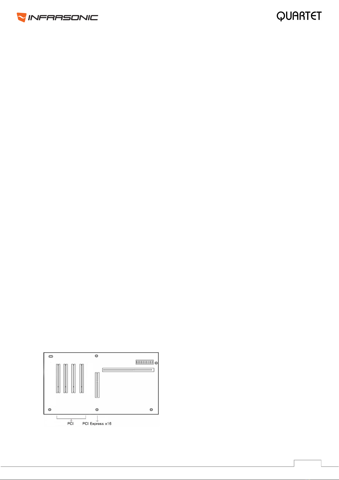
1. Find an empty PCI slot on the motherboard
WHERE IS THE PCI SLOT? - Most computers offer different types of slots. The PCI slot is
common and is used for different types of devices including sound and LAN cards. Usually,
the PCI slot is white. Do not try to connect the card to an AGP slot or PCI-Express slot.
9
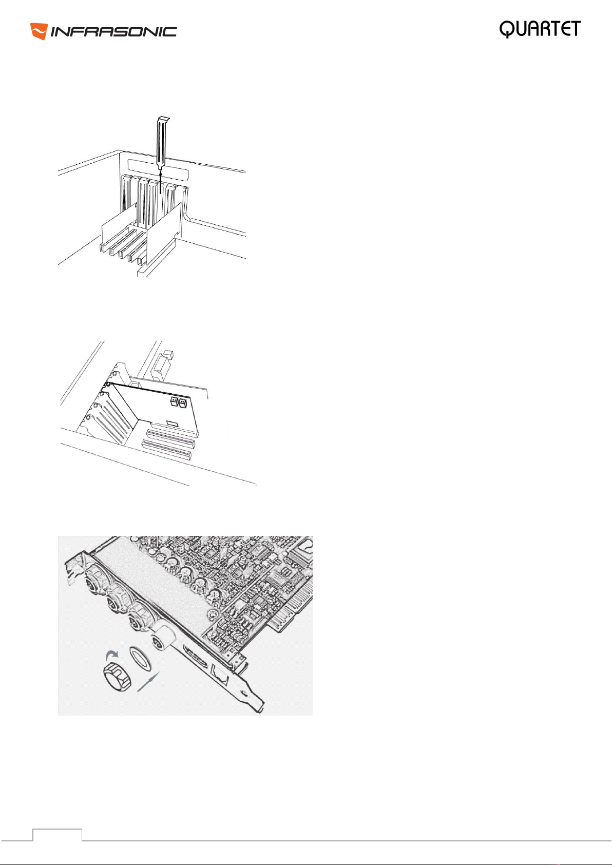
2. If a faceplate or cover is behind the PCI slot, you can remove it by removing the screw
holding it in place or by prying it off with a screwdriver.
3. Pull out the card from the package carefully. Grab the edge of the card. Insert the
QUARTET card into the PCI slot, firmly pushing the card into the slot until it is seated
securely. Replace the screw and tighten it.
4. Afterwards tighten the four screws and isolators of the I/O ports in the clockwise
direction like on the picture below.
5. Close the computer case.
10
4. Driver software installation
After completing the hardware installation of QUARTET, you must install driver software for
Quartet. This manual contains step by step guide for driver installation for Windows PC. If
you have any difficulties installing drivers for other operating systems please contact the
technical support.
NOTE:
Before starting the driver installation, locate your original Windows installation disc, as you
might need it during the process. Also please make sure that you have installed a recent
version of the chipset drivers and patches provided by your main-board manufacturer for
your main-board.
Turn on your computer. Windows will automatically detect a new device and the “Found
New Hardware Wizard” window will appear.
Install QUARTET driver software. Insert the provided CD in your optical disc drive or
download the latest version from www.infra-sonic.com
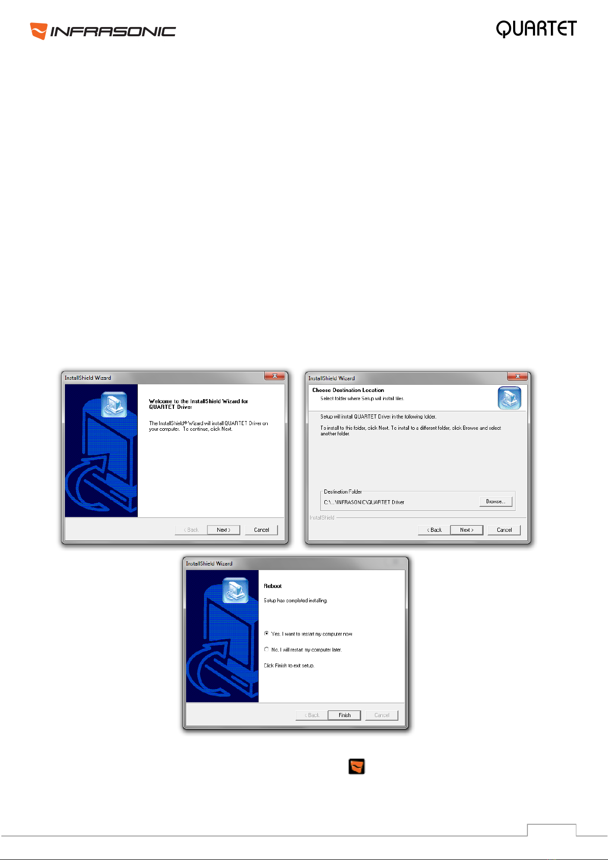
Open the driver folder and simply start the setup file ISQUARTET_v.***.exe and follow the
instructions on the screen.
After the installation has finished, please confirm, if the icon is visible in the system tray
of the task bar.
11
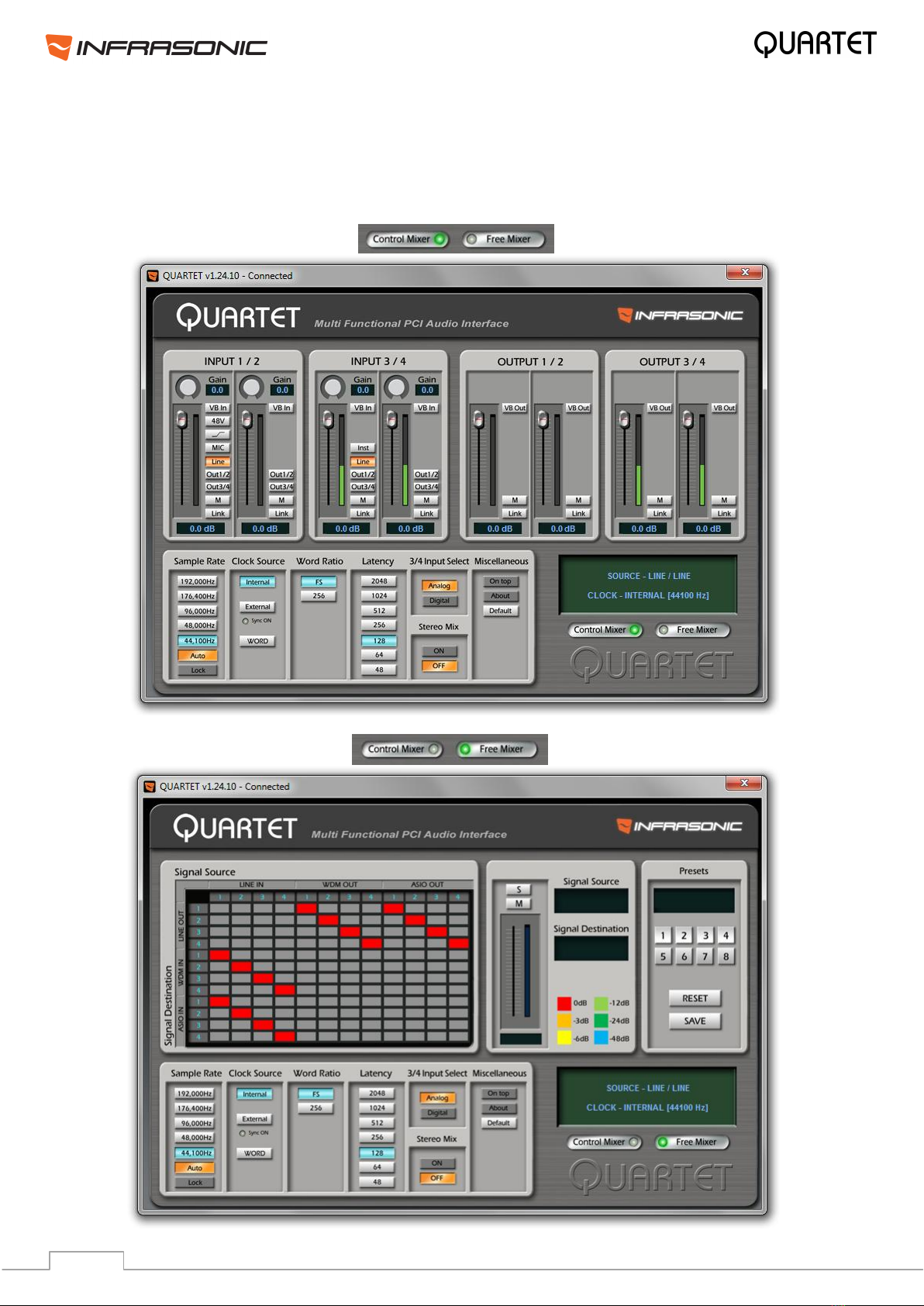
5. The control panel
The control panel consists of the Control Mixer window section and the Free Mixer window
section. By clicking each buttons on the lower right side of the control panel, the selected
window will appear.
12
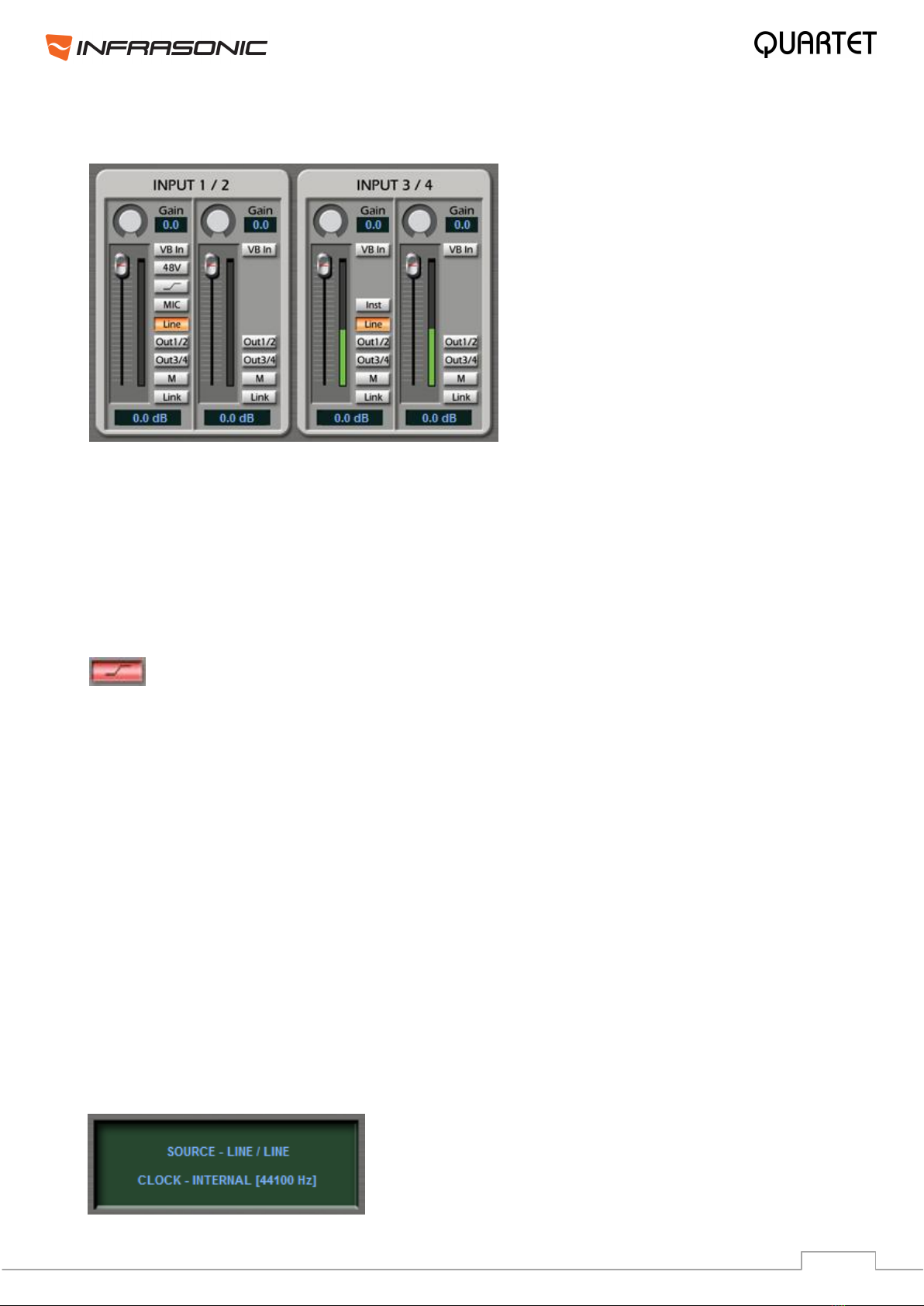
5.1. Control Mixer
• LINE: Enables line level input for inputs 1/2 or 3/4. Orange when selected.
• MIC: Microphone input for input 1/2. Orange when selected.
• 48V: By selecting this button, +48 volts phantom power will be applied to input 1/2 for
condenser microphones. Red, when selected.
Warning: Applying the phantom power to dynamic microphones or other devices might
cause damage and do not forget to enable phantom power only after plugging in the
corresponding 1/4" TRS Jack cable!
• This button activates the Low Cut feature for the microphone input, which
enables a high pass filter above 75Hz. Turns red, when selected.
• INST:Enables Instrument input for input 3/4. You can connect your electric guitar or
bass to this connector.
• OUT 1/2: By selecting this button, you can monitor the input signal through output 1/2.
Blue, when selected.
• OUT 3/4: By selecting this button, you can monitor the input signal through output 3/4.
Blue, when selected.
• VB In: Enables Balanced Input for inputs 1/2 & 3/4. Green, when selected.
• M (mute): Select this button to mute individual signal sources. Red, when selected.
• Link: Connects the input faders by twos and allows controlling them together. Purple,
when selected.
• Volume level faders: Change the signal level of each input. It can be set using the
mouse, mouse wheel, or cursor keys.
• GAIN: These knobs provide additional +18dB gain for inputs.
• Display panel:
It displays the current status of QUARTET.

13
• Output Master faders: Display and change the output level for each source. The level
can be set using the mouse, mouse wheel, or cursor keys.
• M (mute): Select this button to mute individual output channels. Red, when selected.
• Link: Connects the output faders by twos and allows controlling them together. Purple,
when selected.
• VB Out: Enables Balanced Output for outputs 1/2 & 3/4.
• VB In/Out (Balanced Link):
By clicking the button, you can set your Quartet to a balanced 2-in/2-out interface from an
unbalanced 4-in/4-out interface. Depending on your working environment, you can freely
change the setting. This function is available from driver update (v.1.18.4 or later).
Please note, if you are using VB In or Out, only signals routed to Line In/Out 1/2 are
enabled, anything routed to Line In/Out channels 3/4 are disabled. For instance, if VB Out is
enabled, Output 1/2 becomes the balanced left channel and Output 3/4 becomes the
balanced right channel. Also in case of virtual balanced input, only line level signals are
allowed. Read more about this in chapter 6.5.
14
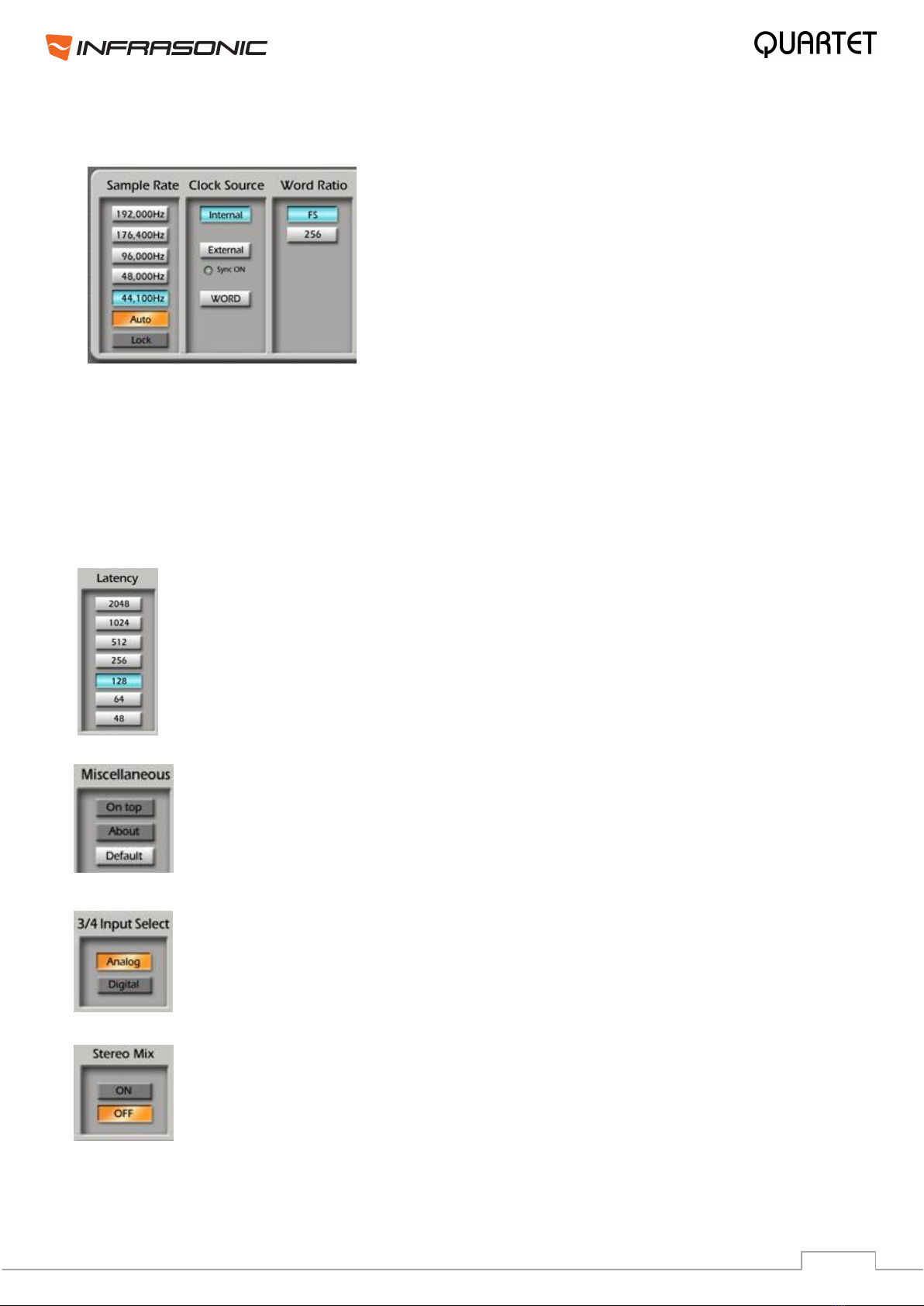
5.2. Configuration section
• Sample Rate: Select and see the current sample rate
of QUARTET. QUARTET supports 44.1, 48, 96, 176.4
and 192 kHz sample rates. Select “AUTO”to match the
sample rate of the source signal automatically. Selecting
“LOCK”allows you to set the sample rate manually.
• Word Ratio: You can choose between FS (standard
word clock) or 256FS (super word clock) settings.
• Clock Source
Internal: Sets the internal clock of QUARTET.
External: Sets the S/PDIF input of QUARTET as master clock. This mode can only be
enabled, if the device connected to the S/PDIF input is configured as clock master.
Word Clock: Sets the Word Clock input of QUARTET as master clock. This mode can only
be selected when the device connected to the Word Clock input is configured as clock
master.
• Latency bar
Adjust the latency (also often referred to as buffer size) of QUARTET. A faster
latency is achieved by selecting smaller sample buffer size, which is ideal for
software synthesizer and timing sensitive recording. However, the latency is also
limited by your system performance. For recording, select a sample size between
64 ~ 512, and select 128 or 256 for Pentium 4 systems. Sample sizes of 48,
1024 and 2048 are used in special circumstances, of which 48 is reserved for
very fast ASIO working environments. The factory default setting is 128.
• Miscellaneous
On top: Enables to display the QUARTET Control Panel always over other
windows. If this is not selected, the active windows of other applications will be
shown over QUARTET Control Panel.
About: Copyright notes.
Default: Resets the control panel to factory default settings.
• 3/4 Input Select
Analog: Selects the analog input for input channels 3/4, while it disables the
digital S/PDIF input.
Digital: Selects the digital input for input channels 3/4, while it disables the
analog input 3/4.
• Stereo Mix
Stereo Mix feature is also called as “What you hear”.
ON: It simply creates new routing rules in Free Mixer and connects WDM
output channels to WDM inputs; hence it allows the recording of WDM output of
your soundcard. More about Free Mixer and its capabilities on the next page.

15
6. FREE Mixer
Flexible Routing Enhanced Engine Mixer is abbreviated to FREE Mixer. It allows connecting
every part of the Hardware in/outputs, WDM, ASIO drivers to each other and themselves. It
provides complete flexibility in an easy to use graphical user interface. According to setup, it
can be used as input monitor, sub mixer, connection between drivers or any purpose you
want.
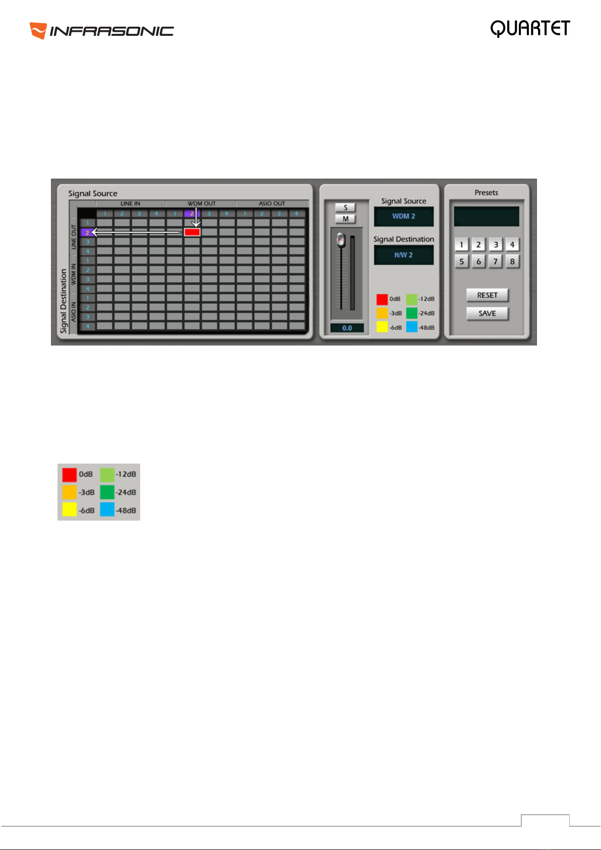
6.1. Matrix Window
The Matrix window shows the connection between source drivers and destination drivers.
Two drivers can be connected by clicking the crossing point between the horizontal line and
the vertical line. In other words, they can be connected when you click the blank square
where two drivers meet together.
• Signal Source:
This part represents signal sources which are routed to different applications.
LINE IN: It stands for Quartet’s hardware inputs.
WDM OUT: It stands for WDM, MME or Direct Sound applications’output such as Winamp
or Windows® Media player. Quartet provides two virtual channels besides of 2 real output
channels, hence it can send four output channels in total.
ASIO OUT: It stands for ASIO application’s outputs such as Cubase or Sonar. Quartet
allows 4 ASIO output channels in total.
• Signal Destination:
This part represents the destination of the routed signal sources.
LINE OUT: It stands for Quartet’s hardware outputs.
WDM IN:It stands for WDM, MME or Direct Sound applications’ input such as Sound
Forge or Vegas. Like WDM output, it provides two virtual input channels beside of 2 real
inputs.
ASIO IN:It stands for ASIO application’s inputs such as Cubase or Sonar. Quartet allows
4 ASIO input channels in total.
•Routing point: This is the colored square which is generated by clicking a meeting point
between Source and Destination. The color indicates the adjusted level of connection which
can be decreased down to -64dB.
16
6.2. How to use FREE Mixer
FREE Mixer creates connection between the sources and their destinations as in the patch
table of a digital mixer. You can adjust the levels, mute and solo signals in this window.
• Select the source signal from Signal Source row and the destination in Signal Destination
column. Odd numbers represent Left channels, while even numbers mean Right channels.
• Left click a grey square and a connection will be created as seen above. In this example
the right WDM output has been routed to the right channel of the analog output 1/2.
• Left click on an existing routing point removes the selected connection.
• Right click on an existing routing point enables solo and mute functions, also level
adjustment is possible, which is separated from the Master I/O sliders settings.
The color of the routing point changes upon adjusting the signal level
from red (0dB) to orange (-3dB), yellow (-6dB), light green (-12dB),
green (-24dB) and blue (-64dB).
• M: This button mutes the corresponding signal.
• S: This button mutes every signal except of the selected one.
• SAVE: After finishing all settings, click the SAVE button and select a preset number. After
clicking the selected preset number, your settings are stored in that preset and you can
recall them anytime.
• RESET: It resets the control panel routing to factory default settings.
17
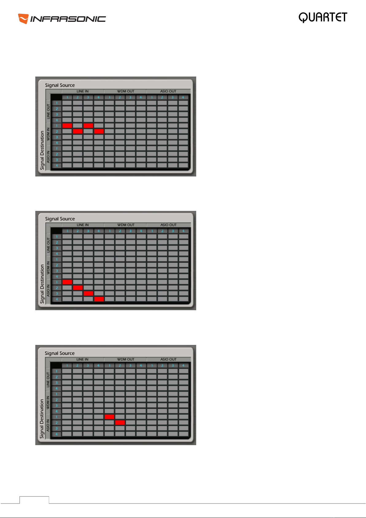
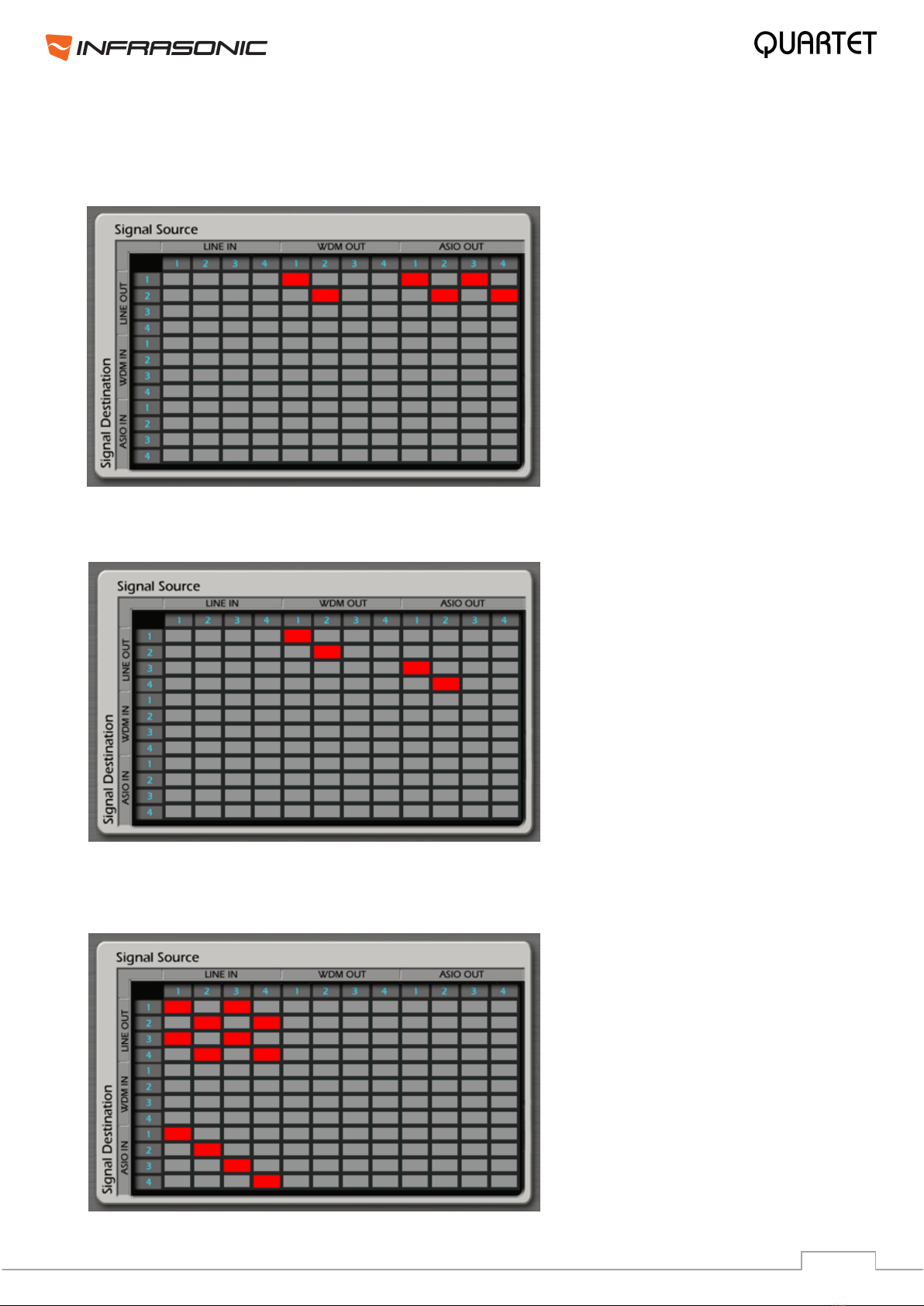
6.3. Examples of usage
1. Routing from H/W IN to WDM IN
H/W IN 1/2 & 3/4 are routed to WDM IN 1/2
2. Routing from H/W IN to ASIO IN
H/W IN 1/2 is routed to ASIO IN 1/2 and H/W IN 3/4 is routed to ASIO IN 3/4
3. Routing from WDM OUT to ASIO IN
WDM OUT 1/2 is routed to ASIO IN 1/2. This way you can record the playback signal of
WDM applications in an ASIO application.
18
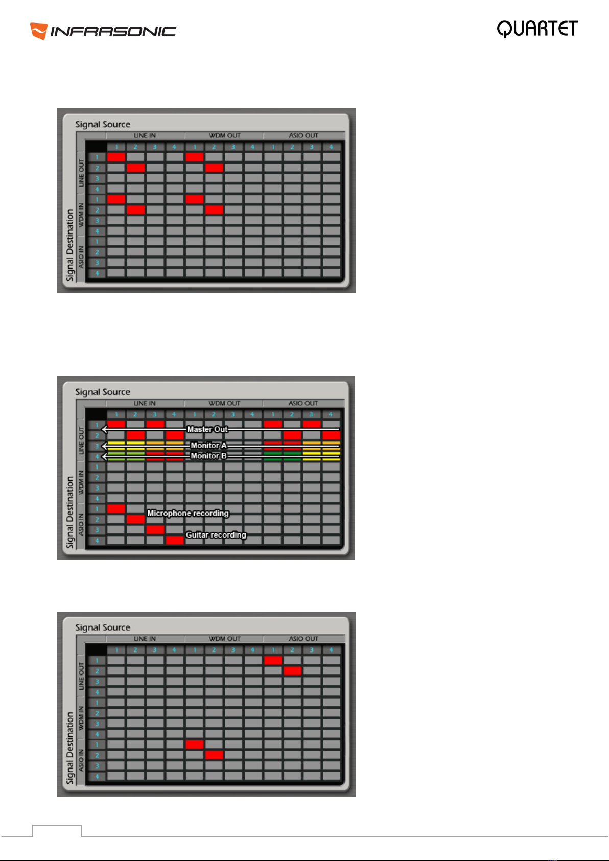
6.5. Practical Examples
Example 1: Listening to all applications’ outputs through H/W output 1/2.
Example 2: Monitoring WDM application through H/W output 1/2 and ASIO application
through H/W output 3/4.
Example 3: In the studio, while recording voice and an electronic guitar in an ASIO
application, monitor the signals in both the control room and the recording booth at the
same time.
19
Example 4: Record your voice cover via a WDM recorder using a microphone and a WDM
playback application. You can mix levels properly using free mixer.
Example 5: Listen to drums VST instrument and a piano VST instrument from ASIO
application on stereo speakers via different ASIO output channels. At the same time, record
voice and guitar on H/W input 1/2 & 3/4, while listening to these signals on the same stereo
speakers. Also send monitoring signal to the musicians in mono and adjust the levels
individually.
Example 6: Apply a global VST effect on your WDM applications (such as games and media
players) from an ASIO VST host via a digital loopback.
Monitoring vocal and guitar
Monitoring drum and piano VSTi
20
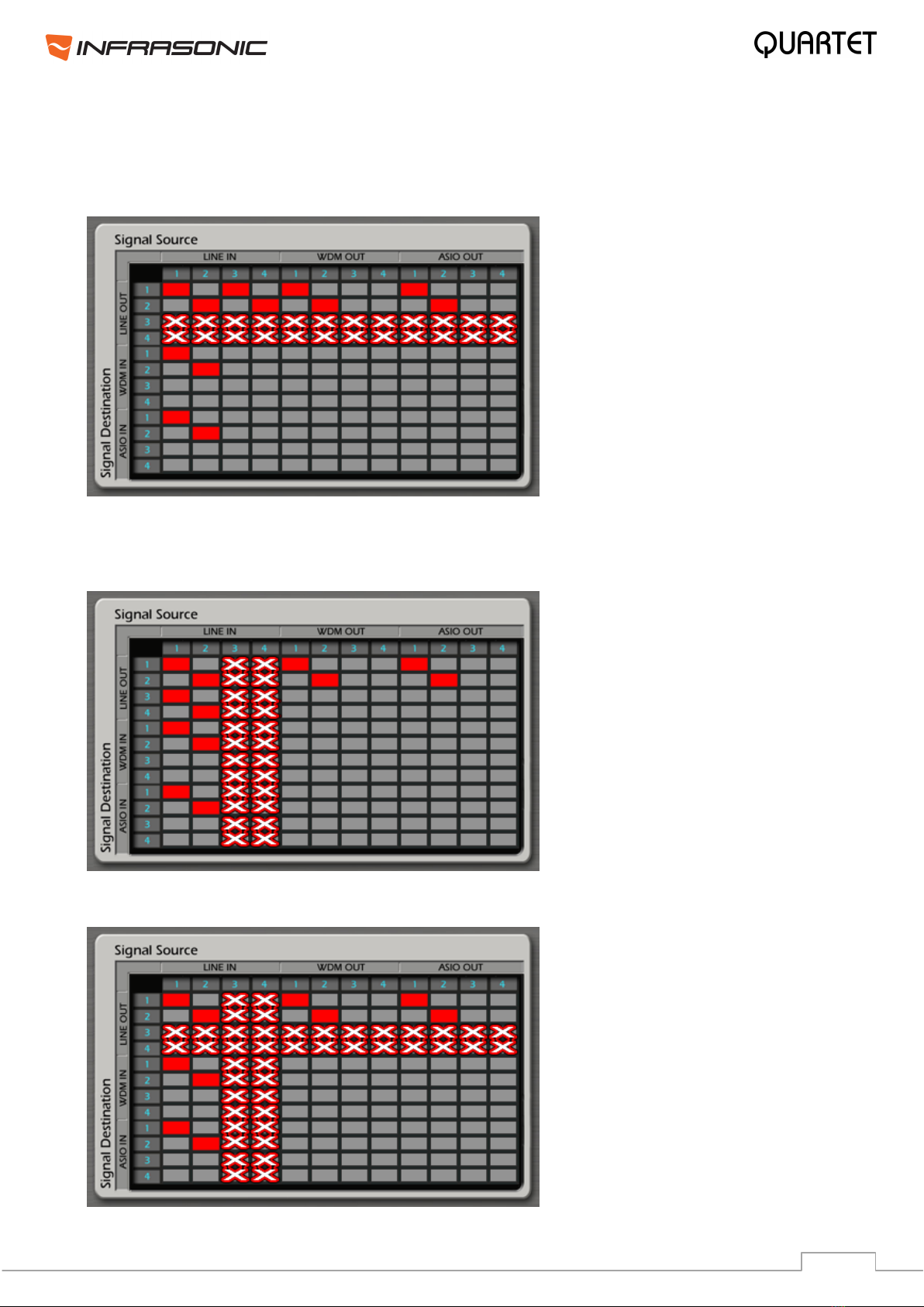
6.5. Balanced Link and FREE Mixer
• Balanced OUT: If Balanced Output is enabled, then those routings are working only,
which are connected to Line Out 1/2. Anything routed to Line In channels 3/4 are disabled.
•Balanced IN: If Balanced Input is enabled, then those routings are working only, which
are connected to Line In 1/2. Anything routed to Line In channels 3/4 are disabled. Also in
case of virtual balanced input, line level signals are allowed only.
• Balanced IN and OUT: The same rules apply as above together.
Recording vocal and guitar
Table of contents
Other Infrasonic Recording Equipment manuals


