Vicon V1300X-IAF User guide

INSTRUCTIONS
FOR INSTALLATION
AND OPERATION
1”“”
MODEL
V1300X-IAF
ALARM INTERFACE
WITH RELAY FOLLOW
1.
INTRODUCTION
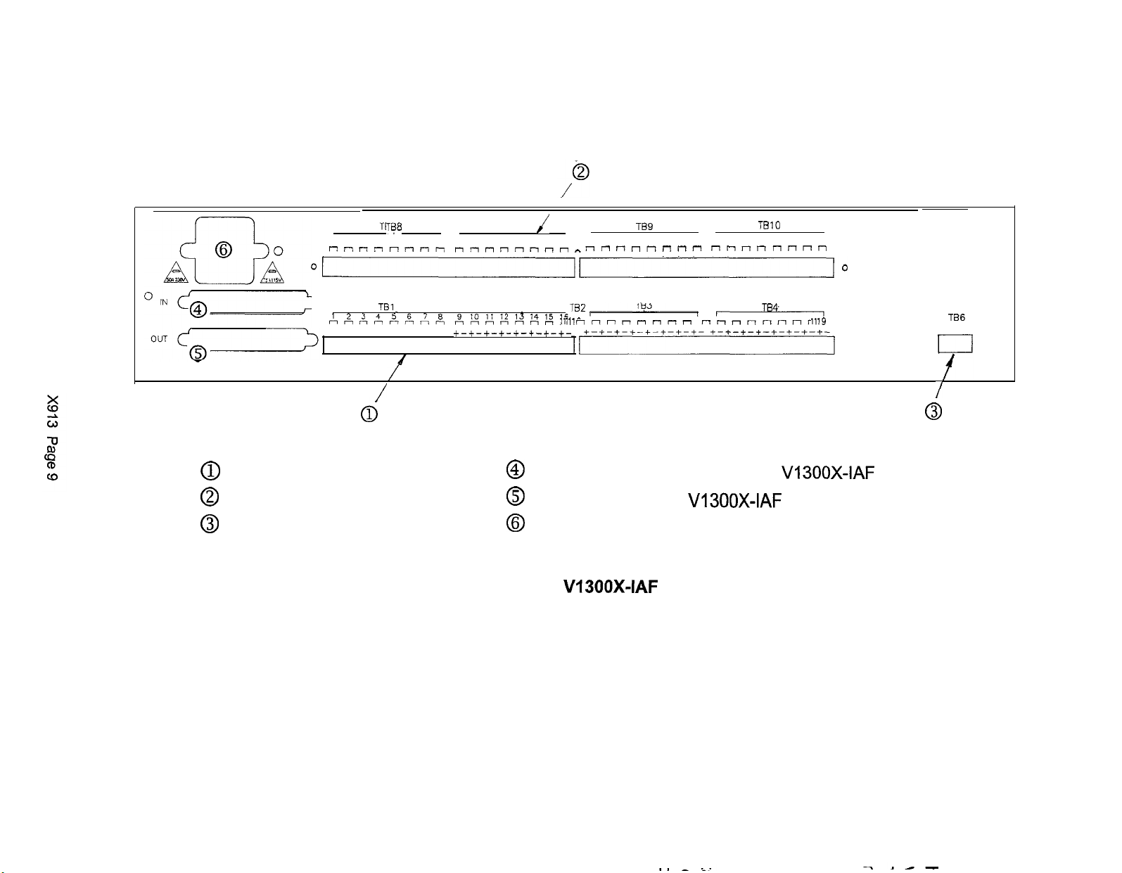
The VI 300X-IAF Alarm Interface with Relay
Follow allows external alarm devices to be
connected to a Vicon
NovaTM
digital control
CPU and provides one dry contact output
relay per alarm input. Each Vl300X-IAF
accepts 32 alarm inputs and provides 32
relay outputs mated to the inputs. Refer to
Table 1 for a list of available models.
Units may be cascaded to accommodate
whatever maximum number of alarm inputs
can be supported by the Nova CPU. Cas-
caded units are interconnected over a par-
allel data interface using cables that are
supplied with each unit. Each
V1300X-IAF
in a cascaded system is programmed with
its own unique address, which defines the
alarm input range and the relay output
range assigned to the unit.
When the V1300X-IAF senses a change in
status of one of its alarm inputs, it transmits
the information to the CPU, which an-
nounces the alarm to the operator and may
TABLE 1
MODELS AND PRODUCT CODES
Model Number
(
Product Code 1Description
VI 300X-IAF I 4759-00
I
120 VAC imut
V1300X-IAF-230 14759-01 1230 VAC input
also execute a preprogrammed response to
the alarm. Such responses include dis-
playing the video from the camera associ-
ated with the alarm on selected alarm
monitors, causing a camera station to carry
out a preset-position program, and dis-
playing a special alarm message on the
alarm monitors. A green LED on the front
panel of the V1300X-IAF glows steadily
during an alarm, and the unit generates a
warning tone. The tone may be disabled.
If the Vl300X-IAF is used with a VPSl300
or VPSI 344 CPU, the alarm inputs function
in the normally closed (NC) mode. If the
X-
IAF is used with a VPS1444, VPS1466, or
VPS1400
CPU, the alarm input mode may
be programmed either normally closed (NC)
or normally open (NO). The output follower
relays always function in the normally open
(NO) mode.
Acknowledging individual alarm inputs is
performed from the Nova operator control
panel. Enabling and disabling individual
alarm inputs is done by software in the
system CPU. TheVl300X-IAF is compati-
ble with the following
CPUs:
VPSI
300
VPSI 344
VPS1444
VPSI 466
VPS1400 (in the future).
Vicon part number 8008-7913-00-00
VICON INDUSTRIES INC., 69 ARKAY DRIVE, HAUPPAUGE, NY 11766
TEL: 516-952-2266; TOLL FREE: 1-600-645-9116; FAX 516-951-2266; UK: 44/(O) 14691566300; INFOFAX: 1-600-267-1207

Units are connected to the CPU over a par-
allel data interface for fast response.
In addition to the relay associated with each
alarm input, an auxiliary relay output is acti-
vated when any input goes active. This
relay may be used to control some external
device, such as a VCR. In the case of mul-
tiple cascaded X-IAF units, only the auxil-
iary relay on the X-IAF that is associated
with the alarm input is activated. The aux
outputs on the other X-IAF units do not go
active.
Alarm Inputs From a Computer
Alarms may be input into a Nova system
either by direct wiring to the alarm interface
units or through an alarm computer or host
computer. Regardless of the source of the
alarm input, the alarms have the same
alarm input number range. Thus, a
VPS1300 CPU in standard configuration
can accept up to 256 alarm inputs, either
through alarm interface units or from an
alarm computer. The alarm number range
remains the same. This affects the
V1300X-IAF as follows: if an alarm (say,
alarm number 27) is input to the Nova CPU
through an alarm computer, the corre-
sponding relay output on the VI 300X-IAF
(relay number 27) is also activated.
1
.I
TECHNICAL INFORMATION
OPERATIONAL
Alarm Inputs: 32.
Alarm Input Mode: When used with
VPSI
300 or
VPSI
344 CPU:
normally closed (NC).
When used with VPSl444, VPS1466, or
VPS1400
CPU: Soft-
ware programmable through the CPU as normally closed (NC)
or
normally open (NO).
Alarm Outputs:
Aux Relay Output Mode:
ELECTRICAL
Input Power:
Power Consumption:
Input Signal:
(1) Signal sent to CPU when alarm input is detected.
(2) Associated “follow” relay activated.
(3) Auxiliary relay activated.
Can be wired either NO or NC.
VI 300X-IAF: 120 V, 60 Hz.
V1300X-IAF-230:
230 V, 50 Hz.
15w.
Secured: Contacts closed (NC) or TTL active low.
Active low = 0.0 to 0.7 V.
Alarmed: Contacts open (NO) or TTL active high.
Active high = 2.7 to 5.3 V.
X913 Page 2

Follower Relay Rating:
Auxiliary Relay Rating:
Fuse:
Fuse Location:
Radio Frequency Emission
Standard:
INDICATORS
Power:
Active Alarm:
CONNECTORS
Alarm Inputs:
Relay Outputs:
Control Input/Output:
Aux Relay Output:
Power:
MECHANICAL
Dimensions:
Weight:
Construction:
ENVIRONMENTAL
Operating Temperature Range:
Operating Humidity Range:
0.1 A at 30 VAC inductive.
0.5 A at 30 VAC resistive.
Dry contacts rated at: 1 .O A at 24 VDC or
0.5Aat
115VAC.
120 VAC model: 0.75 A, 250 V, 5 X 20 mm.
230 VAC model: 0.5 A, 250 V, 5 X 20 mm.
In drawer built into power cord connector on rear panel.
FCC Class A.
Red LED on front panel.
Green LED on front panel and audible tone.
Four 16-pin removable screw terminal blocks.
37-pin D-shell connectors.
3-pin removable screw terminal block.
Detachable 3-conductor cable with grounded plug.
Height: 3.47 in. (8.81 cm).
Width: 19.0 in. (48.3 cm).
Depth: 7.00 in. (17.8 cm).
8.4 lb. (3.8 kg).
Steel.
32 to 122” F (0 to 50” C).
Up to 90% relative, noncondensing.
Product specifications subject to change without notice.
Copyright 01997
Vim!
Industries Inc. All rights reserved.
X913 Page 3

2 INSTALLATION
This alarm interface unit should only be in-
proved materials and practices in confor-
stalled by qualified personnel using ap- mance with federal, state, and local codes.
2.1 Unpacking and Inspection
All Vicon equipment is inspected and tested
before leaving the factory. It is the carrier’s
responsibility to deliver the equipment in
the same condition in which it left the
fac-
tory.
2.1
.I
INSPECTION FOR VISIBLE DAMAGE
Immediately inspect the cartons upon de-
livery. Make a note of any visible damage
On all copies of the carrier’s freight bill.
Make sure the carrier’s agent (the
person
making the delivery) signs the note on all
copies of the bill. If the agent does not
have claim forms, contact the carrier’s of-
fice.
2.1.2 INSPECTION FOR CONCEALED DAMAGE
As soon as possible after delivery, unpack
the unit and inspect it for concealed
dam-
age. Do not discard the carton or packing
materials. If the unit is damaged, contact
the carrier immediately and request forms
for filing a damage claim. Make arrange-
ments for a representative of the carrier to
inspect the damaged equipment.
If the equipment must be returned for
re-
pair, follow the Shipping Instructions at the
end of this document.
2.1.3 Accessory Kit
Table 2 lists the accessories included with
the unit. Verify that all the listed
accesso-
ries are present. In addition to these ac-
cessories, four screws of a type suitable to
attach the monitor mount to the EIA rack
are required. These are commonly No.
IO-
32 screws, but individual rack manufactur-
ers may use other types.
X913 Page4

TABLE 2
ACCESSORIES
1Item No. 1
Component
I Quantitv I
Function
I
I 1I Screws, no. IO-32 x
3/8
flat head I
4I Attach rack mount brackets to unit I
I 2
I
Bracket, rack mounting
I 2
I
Allow unit to be installed in rack
I
3Connector, 3-pin, female
1
Common relay output connector
4Connector, 16-pin, female
8
4 are used for alarm inputs
4 are used for relay follow outputs
5Line cord, 6
ft
(1.8 m)
1
Connects to power outlet
6Data cable, 6 ft (1.8
)
1
Connects to next unit (X-IA, X-IAF)
7
Connector adapter, 37 to 34 pin
1
Allows V1300X-IAF to be cas-
caded with VI 200X-IA interface
8
Rubber feet 4Applied when unit is used in desk-
top installation
2.2 Setting Addresses
CAUTION: Make sure there is no power to
the unit before performing the following
procedure.
Each VI 300X-IAF must be addressed.
This process identifies the range of alarm
numbers that will be input into each UNIT.
Defining the address of the unit is done by
setting DIP switches inside the unit.
To access the addressing DIP switches,
remove the top cover of the unit. Remove
five screws from the top of the cover and
six screws from the rear of the cover to free
the cover. Refer to Figure 1.
There are two DIP switches on the main
(large) printed circuit board (PCB) and two
on the smaller relay PCB mounted above
the main PCB. Refer to Figure 2 for the lo-
cation of the switches. The switches on the
lower board are labeled ADDRESS 1 and
ADDRESS 2. The switches on the upper
board are labeled SW1 and SW2.
DIP switch settings may be indicated on the
switch itself in different ways. Sometimes
the words OPEN and/or CLOSED are used,
but ON and OFF are used more often.
These terms are defined:
ON = CLOSED
OFF = OPEN.
Also, an arrow is often marked on the
switch to indicate the direction of the la-
beled switch status (ON, OFF, CLOSED,
OPEN). Each address DIP switch has four
individual poles that must be set, and the
poles are numbered 1
-
4. The location of
pole 1 is marked on the PC board next to
the switch. Refer to Table 3 for the address
DIP switch settings. To keep the table as
simple as possible, only the ON status will
be marked. A dash means OFF or OPEN.
NOTE: The address set on the relay PC
board must be identical to the address set
on the main PC board.
X913 Page 5

0 0 0
0TOP 0
,.....................,~
0
8,
0
REAR
0
00
0
Figure 1
Location of Cover Screws
Large (main) PC Board
Address 2
0
Address
1
0
FRONT
Relay PC Board
Figure 2
Location of Dip Switches
X91 3 Page 6

TABLE 3
SETTING ADDRESS DIP SWITCHES
I I I I I I
193-224 I
-
on
I
on on on on
225 -256 1
-
1on
I
on I on 1on 1on I on 1on I
After setting the addresses, replace the top
cover. The five flat-head screws are used
on the top of the unit, and the six pan- or
round-headed screws are used on the
back.
2.3 Physical Installation
This unit may be installed in an EIA- or it may be mounted on a desktop or other
standard 1 g-in. (48.3~cm) instrument rack flat surface.
2.3.1 RACK MOUNTING
2.3.1
.I
General Considerations
Observe the following guidelines when
mounting this unit in an instrument rack: 3. Provide a minimum of 1.75 inches (4.4
cm) of empty space between each piece of
1. Plan the layout of the equipment in the
racks before installing equipment. equipment for ventilation.
2. Take an inventory of all rack equipment
including hardware, brackets, blank panels,
etc. Reorder any missing parts immedi-
ately. This avoids delays in the middle of
the assembly process.
4. Use at least one blower/fan per rack.
Place it in the bottom of the rack. Thus, air
is drawn in at the bottom of the rack and
vented at the top.
X913 Page 7

2.3.1.2 Installing the Unit In a Rack
1. Find the two rack mounting brackets
(Table 2, item 2) and the four flat-head
screws (item 1) in the accessory kit.
2. Attach one of the brackets at each end
of the unit with two screws. The long side
of the bracket goes against the side of the
unit. Repeat for the other bracket.
3. Slide the unit into the rack and secure it
in place with four screws. These screws
must be supplied by the installer, as differ-
ent racks have different screw require-
ments.
2.3.2 Desktop Installation
In desktop installations, the rack-mounting
brackets in the accessory kit are not used.
1. Turn the unit upside-down on a soft
surface so that the top of the unit is not
scratched.
one of the feet and attach to the bottom of
the unit near one corner. Place it about
l-
inch in from the two edges. Repeat for the
other 3 rubber feet.
3. Turn the unit right-side up and place it
where desired.
2. Find the four rubber feet in the acces-
sory pack. Peel the covering paper from
2.4 Wiring the Alarm Inputs
CAUTION: Make sure there is no power to
the unit before performing the following
procedure.
TBI : alarms 1
-
8
TB2: alarms 9
-
16
TB3: alarms 17
-
24
TB4: alarms 25
-
32.
Alarm inputs are wired to removable
16-pin
screw terminal blocks which plug into mat-
ing connectors on the rear of the unit. The
screw terminal blocks are packed in the ac-
cessory kit.
Refer to Figure 3. There are two rows of
mating connectors on the rear panel. The
lower row is for alarm input connection,
while the upper row is for the relay follow
outputs.
The lower row, for alarm inputs, consists of
four connectors as follows:
X913 Page8

TB7T@8
/
TB9 TBlO
,
1 2 3 4 5 6 7 8 9 10 11 12 13 14 15 16 17 18 19 20 21 22 23 24 25 26 27 28 29 30 31 32
"r7"l-l~r7"r7l7rlrl~~~~~
~rIr-7"rlr-lr7l-T~
rlr-l~rl"r-l~rl
0000
00
T!31
782
TB4
I
1
I
1
I
AAAAAA,r+r7,,,,rl,,”
91011
1213
14
15
16
~rtrlrlrlr-lr-l~~~~rl11l-lrln
17
16
19
202122
23
24
2526272829303132
TB6
+-+--f-+-+--f-+-+-
+-+-+-+-+-+-+-+-
+-+-+-+-+--f--f-+- +-+-+-+-+-+-+-+- NCCNO
00 0
00
/
/
6
0
0
Al
arm
input connectors @Control IN from CPU or previous V1300X-IAF
0
Relay follow output connectors @Control OUT to next V1300X-IAF
0
Common relay connector @IEC320 power cord socket and fuse tray
Figure 3
Rear Panel of
V1300X-IAF

2.4.1 ALARM INPUT NUMBERING
All card cages are marked with the same alarm input number range, 1
-
32. If the system has
more than 32 alarm devices, then more than one cage is required, and the input number on
the
Vl300X-IAF
will differ from the system alarm number connected to it. The system alarm
number is the number given to a particular alarm device in the overall system.
Tables 4A
through 4H show the system alarm number versus the VI 300X-IAF input number for 256
alarm inputs (eight cascaded V1300X-IAF units).
TABLE 4A
VI 300X-IAF ADDRESSED FOR INPUTS 1
-
32
TABLE 4B
V1300X-IAF ADDRESSED FOR INPUTS 33
-
64
TABLE 4C
VI 300X-IAF ADDRESSED FOR INPUTS 65
-
96
X913 Page10

TABLE 4D
V1300X-IAF ADDRESSED FOR INPUTS 97
-
128
System Alarm No.
119 120
121
122 123 124 125 126 127 128
X-IAF Input No.
23 24 25 26 27 28 29 30
31
32
TABLE 4E
V1300X-IAF ADDRESSED FOR INPUTS 129
-
160
TABLE 4F
Vl300X-IAF
ADDRESSED FOR INPUTS 161
-
192
X913 Page 11

TABLE 4G
VI 300X-IAF ADDRESSED FOR INPUTS 193
-
224
TABLE 4H
VI 300X-IAF ADDRESSED FOR INPUTS 225
-
256
2.4.2 CONNECTING ALARM INPUTS
Each alarm input has two wires, one of
which is a ground. Note on the rear panel
that each alarm number has a + (positive)
terminal and a
-
(negative) terminal. The +
terminal should receive the active or “hot”
wire from the alarm device, and the ground
wire should be connected to the adjacent
terminal marked
-.
Follow the instructions
packed with the alarm device to determine
which lead is ground and which is active.
Back out the appropriate screw on the ter-
minal block one or two turns and insert the
wire in the opening toward the bottom of
the block. Tightening the screw will clamp
the wire in place. Repeat for all alarm in-
puts.
2.5 Wiring the Relay Follow Outputs
The top row of connectors are for the relay
outputs that follow the action of individual
alarm inputs in the bottom row. The relay
follow output numbers correspond to the
alarm input numbers in the bottom row. For
X913 Page 12

example, if alarm input 2 goes active, relay output 2 will also go active.
2.51 RELAY SPECIFICATIONS
Any equipment connected to the relay fol-
l
0.1 amp at 30 VAC with an inductive
low outputs must meet these electrical load load,
limitations:
l
0.5 amp at 30 VAC with a resistive load.
2.6 Wiring the Common Relay Output
In addition to the relay follow outputs that
are dedicated to individual alarm inputs, the
unit provides a common relay output that
activates when any input is activated. The
output connector is TB6 in the lower right
corner of the rear panel. Refer to Figure 3.
The common relay output is commonly
used to control auxiliary alarm-related
equipment.
The electrical specifications of the common
relay are
l
1 .O amp at 24 VDC or
l
0.5 amp at
II
5 VAC.
TB6 has three screw terminals, labeled
NC = normally closed)
C = common or ground
NO = normally open.
Connect the two wires from the auxiliary
equipment (such as a VCR) to two of the
three terminals depending on the action re-
quired by the auxiliary equipment. C is
connected in both configurations.
2.7 Control Cable Connection
The V1300X-IAF is compatible with all
Vi-
con Nova
CPUs.
It may also be intermixed
with VI 300X-IA alarm interface units and
with the older VI 200X-IA alarm interface
units.
CAUTION: Make certain there is no power
to the V7300X-IAF or to the CPU before
performing the folio wing procedures.
2.7.1 CONNECTING THE VI 300X-IAF TO
THE CPU
The VI 300X-IAF is controlled by an exter-
nal CPU and is connected to it with a cable
supplied with the CPU.
NOTE: Use only the cable supplied with
the CPU for connection to the first
V?3OOX-
IAF.
1. Find the cable with two 37-pin D-shell
connectors in the CPU’s accessory kit.
NOTE: Check the cable supplied with the
CPU for labels indicating which end is to be
connected to the CPU and which is to be
connected to the X-IA or X-IAF. Cables
supplied with some CPUs are not marked
this way, and in these cases, either end
may be connected to either device.
2. Connect one end of the cable to the
control IN connector on the VI 300X-IAF,
X913 Page 13

and secure it with two screws. See item 4
on Figure 3.
3. Connect the other end to the alarm in-
terface connector on the CPU, and secure
it with two screws. The screws may be in-
stalled on the cable already or may be sup-
plied as a separate item. Refer to the CPU
manual for the location of the CPU’s alarm
interface connectors.
2.7.2 CONNECTING THE VI 300X-IAF TO 2.7.4 CONNECTING
V1300X-IAF
UNITS
ADDITIONAL VI
300X-IAFs TO V1200X-IA UNITS
If more than one X-IAF are cascaded to-
gether, the cable supplied with each X-IAF
is used to connect the X-IAF card cages to
each other.
1. Find the control cable in the X-IAF ac-
cessory kit. It has a 37-pin D-shell con-
nector on each end.
2. Connect one end of the cable to the 37-
pin D-shell connector labeled “OUT” on the
X-IAF that is closer to the CPU. Refer to
Figure 3, item 5. Secure it with two screws.
3. Connect the other end of the cable to
the 37-pin D-shell connector labeled “IN” on
the next unit in line and repeat for all units.
No more than eight can be connected to-
gether on a single trunk line. Some
CPUs
have more than one trunk line for alarm in-
terface units.
2.7.3 CONNECTING
Vl300X-IAF
UNITS
TO VI 300X-IA UNITS
Follow the same procedure as described in
section 2.7.2 above.
A connector adapter is required to connect
the VI 300X-IAF to VI 200X-IA alarm inter-
face units. This connector is provided in
the accessory kit of the VI 300X-IAF.
I. Connect the end of the adapter with the
34-pin rectangular connector to the
V1200X-IA and secure it with the locking
screw.
2. Connect one of the 37-pin D-shell con-
nectors on the cable to the outboard end of
the cable adapter and secure it with two
screws.
3. Connect the other end of the control ca-
ble to the
Vl300X-IAF
and secure with two
screws.
2.8 Power Cable Connection
The V1300X-IAF is provided with an
IEC320 recessed power connector and a
detachable power cord. Locate the IEC320
connector on the upper left side of the rear
panel (refer to Figure
3),
and securely plug
the power cable into it. Connect the other
end of the power cable to a suitable power
outlet. The unit is powered up and
operat-
ing as soon as the power cable is con-
netted.
X913 Page 14

2.9 Programming the CPU
When using one or more
Vl300X-IAF
units
with any of the VPS Nova CPUs, it is nec-
essary to disable the remote acknowledge
function in the CPU on-screen menus. This
must be done for any system using a
VI 300X-IAF or VI 300X-IA, even if there is
a mixture of alarm interfaces including the
older VI 200X-IA.
1. To perform this programming function,
bring the Main Menu up on screen following
instructions in the CPU Programming Man-
ual. Different CPU models may display this
information in slightly different formats.
2. Select ALARM FUNCTIONS, which will
display the Alarm Functions Menu.
(The previous alarm interface model, the
V1200X-IA, had a front-panel button that
allowed alarms to be acknowledged at the
Vl200X-IA. In contrast, all alarm inputs to
the V1300X-IAF and
Vl300X-IA
are ac-
knowledged through the operator keypad or
automatically by the CPU, so that no ac-
knowledgment button is provided.)
3. Select X-IA ENABLE/DISABLE, which
will display the X-IA Enable/Disable Menu.
4. Select SET ACK.
ENA/DlS
to display
the programming screen for the acknowl-
edge enable/disable. Follow the on-screen
instructions to change ENABLED to DIS-
ABLED.
3 OPERATION
The
V1300X-IAF
has two
LEDs
and one
Green LED: Indicates that one or more
slide switch on its front panel: alarms is in progress.
Red LED: Indicates that power is supplied
to the unit. Slide switch: Turns the audio alarm tone
on or off.
4 MAINTENANCE
The VI 300X-IAF requires no scheduled
maintenance. If it is necessary to change
the fuse, locate the IEC320 connector on
the rear panel (Figure 3). Remove the
power cord from the connector and slide
out the fuse drawer using a fingernail or
small screwdriver.
Remove the old fuse and place a new fuse
in the clip. Replace the fuse drawer and
reconnect the power cord. The correct fuse
value is indicated in a triangle on the rear
panel next to the fuse drawer.
X913 Page 15

Shipping Instructions
Use the following procedure when returning a unit
to the factory:
2.
Attach a sheet of paper to the unit with the fol-
lowing information:
1.
Call or write Vicon for a Return Authorization
(R.A.) at one of the locations listed below. Record
a.
the name of the Vicon employee who issued the
R.A.
b.
VICON INDUSTRIES INC.
89 Arkay Drive
C.
Hauppauge, New York 11788
5 16-952-CCTV or toll free l-800-645-9116
Fax: 5 16-95 l-CCTV
d.
e.
For service or returns from countries in Europe,
contact
VICON INDUSTRIES (U.K.) LTD
Complete description of the problem and
circumstances under which it occurs
Unit’s original date of purchase, if still under
warranty
Brunel Way
Fareham, PO15 5TX
United Kingdom
f.
3.
Pack the unit carefully. Use the original shipping
carton or its equivalent for maximum protection.
Name and address of the company returning
the unit
Name of the Vicon employee who issued the
R.A.
R.A. number
Brief description of the installation
44/(O)
148$?577775
Fax: 44/(O) 1489/578923
4. Mark the R.A. number on the outside of the
carton on the shipping label.
X913 Page16
Table of contents
Other Vicon Recording Equipment manuals

Vicon
Vicon VDR Administrator Guide

Vicon
Vicon Aurora 99 V800KBD User manual

Vicon
Vicon V1400X-MSSV User manual

Vicon
Vicon AurorAcord User manual

Vicon
Vicon VDR-208 User manual

Vicon
Vicon NOVA V1400X-HSB-M User manual

Vicon
Vicon Valerus-PoE NVR User manual

Vicon
Vicon V1311R-VPS-1 User manual

Vicon
Vicon AurorAcord XX091 User manual