Infrasonic Windy6 User manual

- 0 -

1. Introductio
n
Con
g
ratulations on choo
s
providin
g
hi
g
h quality au
FireWire Bus; the Windy
6
and 2 di
g
ital output audi
o
This user’s manual is int
e
and run the Windy6
■Full Features
• 6-in/ 6-out FireWire Hi
g
• 4-in/4-out analo
g
I/O,
2
• 4 balanced inputs
- 2 x NEUTRIK® XLR/T
R
- Flexible Line/Hi-Z inp
u
- A/D converter: Dyna
m
• 2 x MIC pre-amp featu
r
- +48V Phantom powe
r
- Channel Insert 1/2 fo
r
• 4 Servo-balanced outp
u
- D/A converter: Dyna
m
• Coaxial type S/PDIF I/
O
• Supports up to 24-bit/1
• 16ch MIDI I/O
• Affordable 2 FireWire p
o
• Heavy-Duty Aluminum
b
• Hi-gain and Hi-powered
• Controllable the mixed
l
• ASIO2, WDM, DirectSo
u
• Core Audio/ Core MIDI
s
■Minimum syste
m
<PC>
Intel Pentium 4 or equiva
512MB of RAM
One available FireWire (I
E
Microsoft Windows® XP/
V
■What’s in the bo
• WINDY6 Hardware
• Installation CD (Driver
a
• Standard FireWire cabl
e
• Quick Start Guide
• External DC Power Sup
p
- 1 -
n
to Windy6
s
in
g
the INFRASONIC Windy6 Audio/MI
D
dio and MIDI in and out of your comp
6
g
ives your computer hi
g
h quality 6 i
n
o
interface.
e
nded to
g
ive you a step by step
g
uide
g
h-Performance Audio/MIDI interface
2
-in/2-out S/PDIF I/O
R
S combo
j
ack, 2 x 1/4inch TRS phone
j
u
t
m
ic Ran
g
e 113dBA
r
es on front panel
r
connectin
g
serial out board effects
u
ts (1/4inch TRS phone
j
ack)
m
ic Ran
g
e 115dBA
O
92kHz
o
rts – available multi-devices link
b
ody
class AB headphone amps
l
evel between output 1/2 and output 3/
4
u
nd supports
s
upports
m
requirements
lent and Compatible CPU
E
EE 1394a) port
V
ISTA or later
<Mac>
Macintosh
512MB of
One avail
a
Mac OS 1
0
D
I Interface, all round
g
ear for creatio
n
uter. It features hi
g
h-speed IEEE-1394
a
n
puts, 6 outputs includin
g
2 di
g
ital inp
u
x
a
nd Bundle software)
e
p
ly
of the Infrasonic Windy6, to
g
et you u
s
j
ack
4
with G4 or better processor
RAM
a
ble FireWire (IEEE 1394a) port
0
.3 or later
n
,
a
,
u
t
s
e
- 2 -
2. Description of Windy6
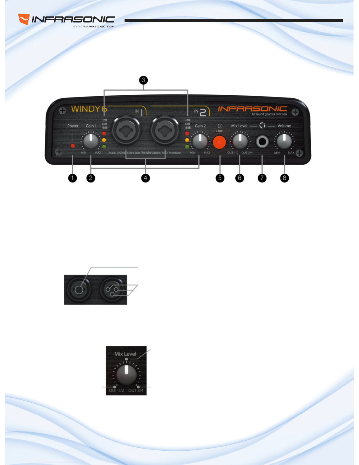
■ Front Panel
1. Power Indicator LED –Indicates the status of power supply and digital input
2. Input Gain Control – Control input level of each microphone or line input (for both XLS and TRS)
3. SIGNAL and CLIP LED – Indicates the signal level of input 1/2 and clipping
4. INPUT 1/2 Connector – Analog Balanced XLR/TRS (NEUTRIK® Combo) Input Connector
●Combo connector
TRS / Line, Instrument
XLR/ MIC (MIC must be connected by XLR)
5. Phantom Power (+48V) Switch – Supply 48V DC phantom power to input channels 1/2
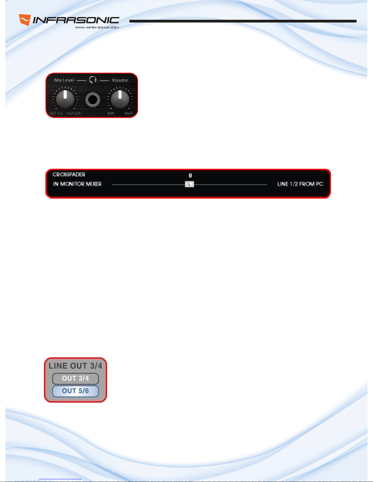
6. Mix Level Knob –Headphone output can be selected between out 1/2 out 3/4 by “Mix level knob”
●Mix level Knob
Mix 50%
OUT 1/2 only OUT 3/4 only
7. Headphone Output – The high powered stereo Headphone output
8. Headphone Level knob – Control the level of Headphone output

- 3 -
■ Rear Panel
1. Power On/Off switch
onnector – Connect to the included DC adapter
ter usually, the bus power
3.
er using the included six-pin IEEE1394a(FireWire) cable.
4. ls I/O
Coaxial) for digital connection
ecting serial out board effects such as compressors
7. I
Connector
S Connector
adjusting output level of unbalanced and
2. External power supply c
– Note: If you have 4-pin FireWire connector that features on a lap-top compu
can’t be supplied. It should be required the external power supply
IEEE 1394a(FireWire) Port
– Connects the Windy6 to your comput
– 2 more Windy6s can be linked and used as multi-Device.
(It should be required the external power supply)
MIDI In/Out Port – Windy6 provides 16 MIDI channe
5. S/PDIF 5/6 In/Out Connector
– Windy6 has S/PDIF input and output(
6. INSERT 1/2 Connector
– Channel Insert 1/2 for conn
(Tip : Send /Ring : Return)
NPUT 3/4 Connector
– Analog Balanced TRS Input
8. OUTPUT 1/2/3/4 *Servo-Balanced TR
– The 4 output jack is built in a servo-balanced design,
balanced automatically.

- 4 -
●Servo-balanced description
1, Typical Balanced Output
Fig1. Balanced connector
Balanced signal output is transmitted along with its phase reversed signal (RING) and the output signal
level will be amplified by the differential Amp as twice.
Fig2. Balanced Signal Output Flow
If the balanced output is connected Unbalance jack, the actual inside connection would be TIP & Sleeve
only so the output signal level will be the same as TIP. That means the output level is half (-6 dB) of
Balanced output. (See Fig3)
Such level loss has large influence to not only noise level but also level setting between equipments.
Fig 3. Unbalanced Signal Output with Balanced connection

- 5 -
2, Servo-Balanced Output
To minimize such sound level loss due to the different type of connectors, Servo- Balanced Output
controls its gain level in automatically to keep the same level between unbalanced and balanced type
signal.
Fig 4. Unbalanced Signal Output with Balanced connection
When unbalanced signal being input, Servo system is automatically recognized that there’s no signal is
feeding from RING and feed amplified signal back to TIP and that makes it flow without any SPL
attenuation in any condition.
Servo-Balance technology makes you free from the connector type problem between unbalance and
balance. Easy and simply hook your equipment up, that possible between of different I/O signals.
Fig 5. Unbalanced Signal Output with Balanced connection

- 6 -
3. Connections
1. Find the FireWire port on the rear of the Windy 6
2. Connect the included FireWire cable to the FireWire port of the Windy6
3. Find FireWire port on your computer
4. Plug the included the FireWire cable to the FireWire port of your computer.
5. Connect your equipments to the Windy6 (mixer, monitoring system, recorder, etc.)
6. Have a Fun with the Windy 6!
- 7 -
■ Connections Descriptions.
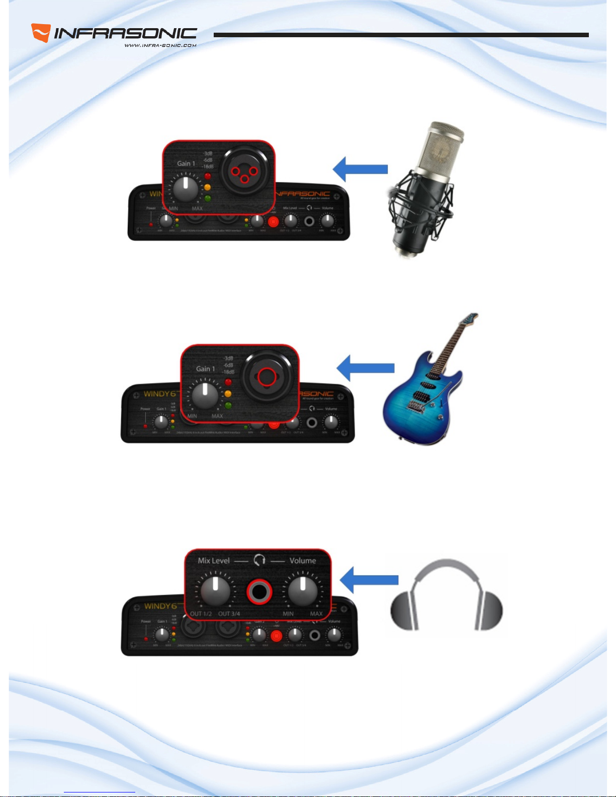
1) Microphone
• Microphone connects to Input 1/2 on the front panel of Windy6.
• Please note that mictophone should be connected by XLR type only.
• Select “Inst“ on the control panel as input source.
• Adjust gain using Knob on the front panel to control the input level.
2) Instrument
• Instrument connects to Input 1/2 on the front panel of Windy6
• Please note that instrument should be connected by TRS/TS type only.
• Select “Inst“ on the control panel as input source.
• Adjust gain using Knob on the front panel to control the input level.
3) Phone
• Headphone connects to HP connector on the front panel of Windy6.
• Using Mix Level knob, the headphone output can be monitored both output 1/2 and 3/4 simultaniously
or selectable. (Left: output 1/2 100% , Mid: 1/2 50%, 3/4 50%, Right: output 3/4 100%)
• Headphone output level can be controled by headphone volume knob.

- 8 -
4) MIDI controller
• MIDI OUT in your MIDI controller connects to MIDI IN of Windy6.
• If you use an external MIDI instrument, MIDI OUT of Windy6 conects to MIDI IN of your MIDI device.
5) External out board effect
• Your external processor can be connected via Insert connector.
- Input 1 -> Insert 1, Input 2 -> Insert 2
• Y-typed canble is required to use Insert connector with your external processor. Connects between
Windy6 insert and in/out of your device. (Tip : send / Ring : return)
6) Studio monitor
• Speaker connects to out put 1/2, 3/4.
• It is able to select a single stereo or dual stereo output from 1/2 and 3/4.
•. SPDIF out(out 5/6) connects to SPDIF supportable device.
- 9 -
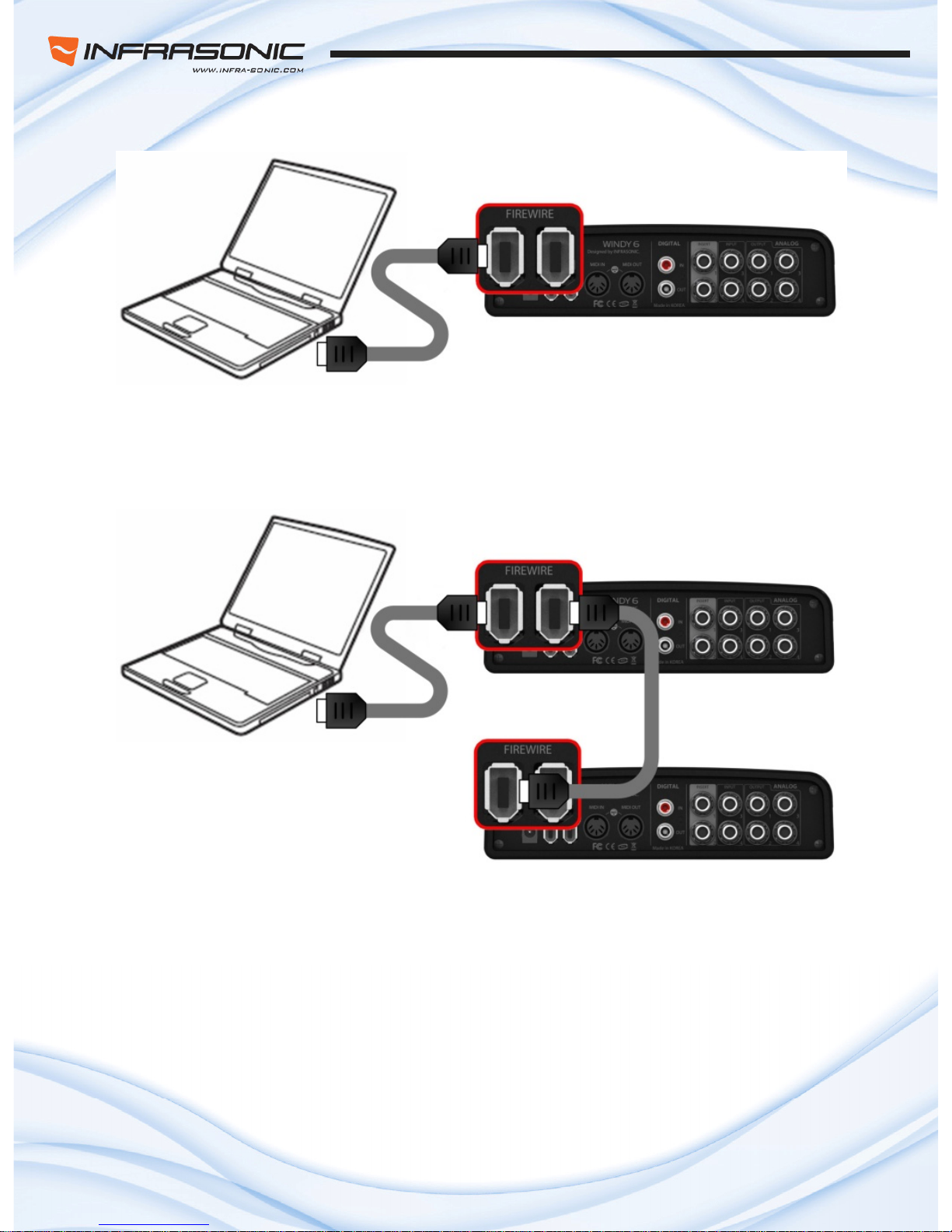
7) Computer
• IEEE1394 cable connects between computer‘s IEEE1392 port and Windy6‘s IEEE1392.
• laptop should use with 4/6PIN connector that includes the package.
• Laptop should conennect with the external adaptor that includes in packsge for correct working.
●Using multi device
• Windy6 supports multi-device function that allows to use 2 more Windy6 at the same time.
• No1 Windy6 connects to computer and other 1394 port connects to No2 Windy6 1394 port to use
mutiple Windy6 simutaniouly.
• To use Multi device function should require DC adaptor for correct working.

- 10 -
4. Software installation
■ Driver installation
This manual contains a step by step guide for driver software installation to your OS. If you have any
difficulties during installation, please contact our technical support department.
Install the WINDY6 driver software. Install the provided CD in your CD-Rom drive. Open driver folder and
just click setup file and follow the instruction on screen.
NOTE:
Before starting the driver software installation, locate your original OS software disc, as you may need it
during installation. Also please make sure that you have installed the most recent version of the chipset
drivers and patches provided by the manufacturer for your motherboard.

- 11 -
5. Control panel
The control panel provides you a useful multi channel software mixer with adjustable 6 virtual inputs and
outputs. Each of output pair can be routed to any of the Windy6’s four analog or two digital outputs.
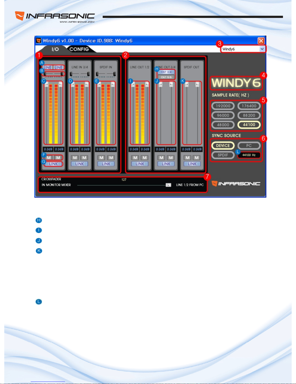
■In/Out Tap
1. Input Control Section
Line/Instrument selector – Select the input source between line and instrument(mic)
B Pan control fader – adjust the pan value of left and right channel.
Input 1/2 level – control the input 1/2 digital gain level.
Input 3/4 level fader – control the input 3/4 digital gain level.
E) Input 5/6(SPDIF) level fader – control the input 5/6 digital gain level.
Mute button – Mute the sound
Link button – Link the left and right channel’s fader
- 12 -
2. Output Control Section – Output volume level control.
Output selector – Select the Output source for output 3/4 between out3/4 and 5/6(SPDIF)
Output 1/2 level control
Output 3/4 level fader control
Output 5/6(SPDIF) level fader control
3. Device selector – Select the controllable device when using multi device.
4. Windy6 LOGO – Turn on when connecting between computer and wind6 is stabilized.
5. Sample Rate – Select the Sample Rate up to 192kHz.
6. SYNC Sours select – Select Sync Source for another digital device syncronization.
Sample Rate indicator – Indicates the current Sample Rate from master device.
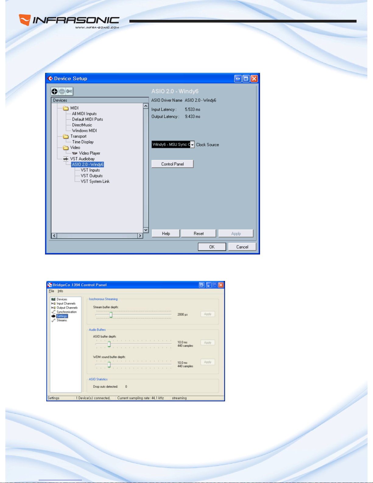
7. Crossfader – Control mixing balance between input monitor sound and internal PC sound.
It will be set center position back by double-clicking on the fader.

- 13 -
■Config Tap
1. Adjust Buffer Size / Adjust and apply the stream, ASIO/WDM buffer size
2. ETC / TOP WINDOWS : This enables the Windy6 panel to be always displayed on the top.
RESTORE DEFAULT : Restore the Windy6 to the default factory setting for all configurations.
ABOUT : Shows the information of controlpanel
This control panel provides you access to assign the Input/ Output level control, cross fader, sync source,
configuration, and choose sample rate for your creation. In addition, you can assign instrument or mic for
channel 1 and 2 depending on your equipments. You can hear “tick” sound when you change input mode
from instrument to Mic or vice versa regarding to your device. Also, you can set up master clock, buffer
size and other various features by simply clicking.
- 14 -
■Various Monitoring Function
1. Headphone
Headphone output can be selected between out1/2 and out3/4 by
“Mix level” knob control. The middle position can be heard the
sound of both out1/2 and out3/4 at the same level. It works like a
genuine DJ mixer headphone monitoring system and ideal for DJ
Fig 1 . Headphone Mix Knob software in various ways.
2. Cross fader in the control panel
Fig 2 . Monitor Cross Fader
I MONITOR MIXERN
‐All input 1, 2, 3, 4, 5, 6 (Both analog and digital) can be heard this fader position. Please note
that the monitor signal goes through out 1/2 only.
L NE 1/2 FROM PCI
‐This is able to hear OUT 1/2 what you’re playing currently.
The cross fader is useful to monitor from various input signals at the same time and also it is able to
mix with your current play back sound. As the fader position, monitor level can be changed between
Input and output but middle position will be heard at the same level from both.
3. SPDIF monitoring
In general, digital output can’t be monitored without additional converter
But Windy6 do. Just simply select which IO group you want to hear on the
contro
l panel (OUT 5/6 = SPDIF output). It is useful function for Infrasonic
Fig 3 . SPDIF Monitor monitored also via OUT 1/2 that mentioned above.
Blow D series speakers to diagnostic SPDIF works correctly. And SPDIF
can be

- 15 -
6. Using whith Applications
Please refer to the specific software’s manual for detailed information.
■Cubase SX and Nuendo
1. After launching Cubase SX, go to Device ÆDevice Setup ÆVST Audiobay.
Select ‘ASIO2.0-WINDY6’ for the ASIO device. Make sure you need to click Apply button
after changing the settings.
<Audio Setup in Cubase>
This chapter contains examples of basic configuration for some popular software applications.
- 16 -
2. After changing the settings, go to Device ÆDevice Setup ÆASIO2.0-WINDY6
Click the ASIO tab. You can change
system performance and application
priority.
Your system performance affects the
latency of the inputs and outputs.
program.
If you click the Control Panel button, ‘ASIO-USB Control Panel’ window will pop up.
If you want to change the sample
rate, you must change it on the host
- 17 -
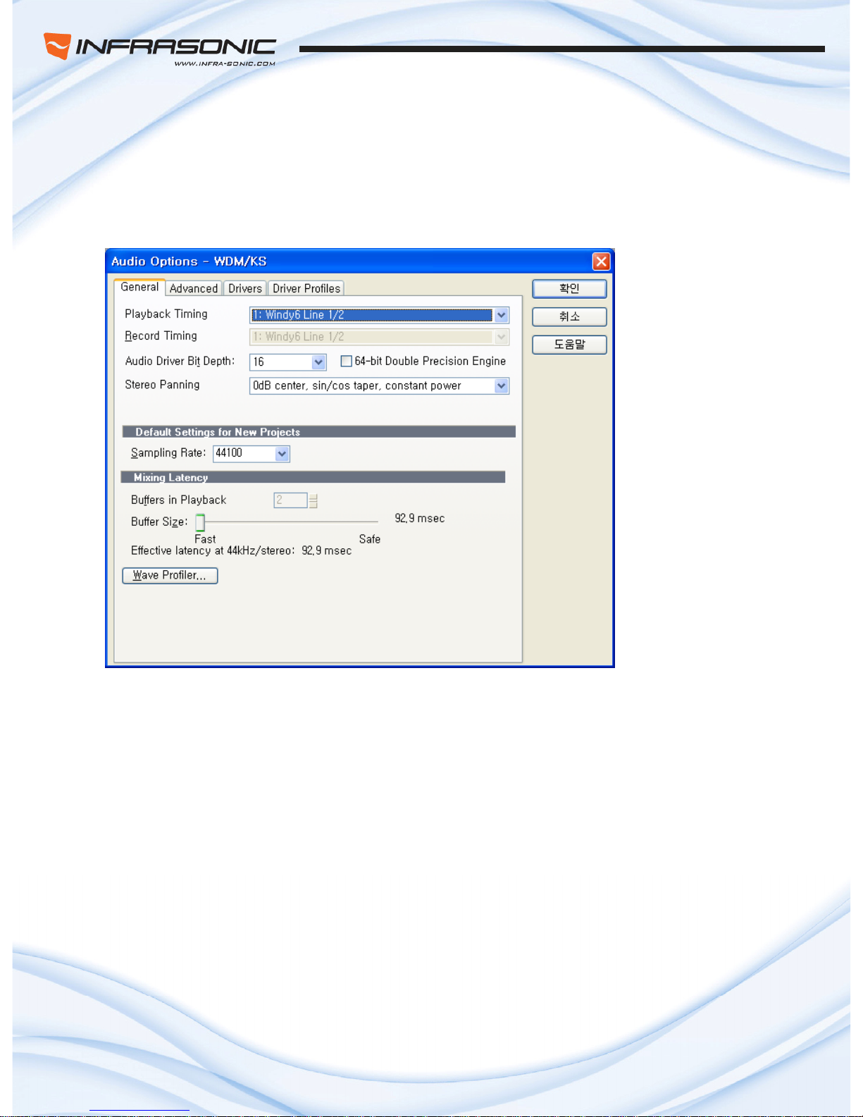
■Cakewalk SONAR
There are few steps must be done for the SONAR which may supports both WD
l
M and ASIO. After
aunhing SONAR, go to option ÆAudio tab.
KS mode
<Audio Setup in Sonar>
he input and output drivers have to be matched to each other.
Restart SONAR after the settings have changed.
1. WDM/
Change the settings as above in the input/output driver settings.
T

- 18 -
2. ASIO mode
First, change the driver mode to ASIO in the
advanced tab of the audio options as below,
then restart SONAR.
condly, change the settings as above in the input/output driver settings.
<Driver Setup in Sonar>
Se

- 19 -
■MAGIX Samplitude
After launching SAMPLITUDE, go to Device ÆDevice
Select ‘ASIO2.0-WINDY6’ for the ASIO device. Make s ging
the settings.
<Audio Setup in Samplitude>
Setup ÆVST Audiobay.
ure you need to click Apply button after chan
Table of contents
Other Infrasonic Recording Equipment manuals


