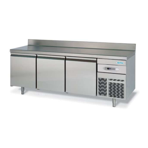
Infrico Vitrine User manual

Review: 00 Date: May 31, 2018 Page: 1 to 13

2
INDEX
1. Introduction ……………………………………………….…………….. 3
2. Warning ……………………………………………….…………………… 3
3. Description…..…………………………………………….……………… 4
4. Transport and mobility………………………………….…………… 4
5. Conditions of use and Technical specifications…….…..... 4
5.1 Command and control.………..……………………….…...... 5
5.2 Protection and safety device………………………….…….. 5
6. Installation……………………………………………………………..... 6
6.1 Preliminary operations….……………………..……….……. 6
6.2 Positioning…….………………………….………..……………... 6
6.3 Water connection..…………….………………..…….………. 7
6.4 Electrical connection.………………………….....……….…. 7
7. Operation and use.…………………………………………………... 7
7.1 Advice for use…….……………………………….………….…. 7
7.2 Start-up Bain-Marie………………………………..……….…8
7.3 Start-up glass-ceramic hob…..………………….…..……. 8
7.4 Start-up of cold elements…..………………….…..…..…. 9
7.5 Disconnection……………………………………………………. 9
8. Cleaning and maintenance……………………………….……… 10
8.1 Cleaning procedure……………………………..………….…10
8.2 Special maintenance ……………….……………………….. 10
8.3 Trouble shooting chart………………….……..………...... 11
9. Recycled………………………………………………………….……... 13
Annex Nº1……………………………….........…………………...….... 13

3
1. INTRODUCTION
This manual has been made in a simple way so that by reading it you can know the operation
and maintenance of our furniture. It is recommended to read it carefully and keep it for any query.
The manufacturer is not liable for damages to persons or objects that may be caused by non-
compliance with the prescriptions contained in this manual. Anyone who uses this device is
recommended to read this user manual. In case of any doubt consult your distributor.
This furniture comply with directive 2004/108 / CE, 2006/95 / CE. In addition, CEI EN 60335-1,
CEI EN 60335-2-49, CEI EN standards have been applied
60335-2-50, EN 61000-3-2 and EN 61000-3-2.
2. WARNING
Warning, read this manual before to installation. This manual is designed to give all the
information for use the unit safely from transportation to the final installation.
This manual should be retained for future reference.
In case of cession the unit, this manual must be delivered to the new user.
For a correct use of the unit:
•Not handle the security device.
•Used only for their specific functions.
•Avoid the presence of stranger in the vicinity of the unit.
•Used exclusively for qualified maintenance personnel.
•Disconnect the unit in case of malfunction.
•Use only original spare parts.
WARNING: Access to the main electrical panel and electrical parts, must be qualified
personnel.
The manufacturer declines all responsibility for damage to persons or things caused by
incompletion of the operating instructions.
In case of doubt consult your dealer.

4
3. DESCRIPTION
There apparatus of cold and hot elements is composed of a tank or plate inserted ina a cabinet
with support, and a heating or cooling group housed in the bottom of the tank. The control panel is
located in the lower rear part where you can control the temperature.
The element Bath Maria and cold elements is available with the unified dimensions GN 2 1/1,
GN 3 1/1, GN 4 1/1, GN 5 1/1 (Drop-in) and 6 1/1 (Self), to be installed in collective facilities varying the
configuration.
The heating group is composed of a number of variable resistors (from 2 to 5) according to the
dimensions of the tank.
Similarly, our ceramic hob is composed of a cupboard where the glass ceramic hob and its
corresponding temperature control are placed, placed on the laterally located board. It is available in
the unified dimensions GN 2 1/1, GN 3 1/1 and GN 4 1/1.
4. TRANSPORT AND MOBILITY
The equipment, which is located on a pallet must be downloaded elevator truck or other
machine for this function. Any error of maneuver will cause damage in the equipment.
The staff perfoming the download, you must be provided with appropriate protective measures
(gloves, etc…).
5. CONDITIONS OF USE AND TECHNICAL SPECIFICATIONS
The cold and heat elements, and the glass ceramic element have been manufactured exclusively
to maintain and expose hot or cold foods, located in unified buckets, in premises destined for collective
catering.
The maximum operating temperature of tank is 90ºC, the glass ceramic is 130ºC. The maximum
operating temperature of the hot interior is 60ºC.
The temperature of cold elements depends on each model described in the attached table:

5
MODELS
TEMPERATUR RANGE
Vitrine
+4ºC/+12ºC
Cold Plate
-4ºC/+4ºC
Cold Tank
0ºC/+6ºC
Reserve
+2ºC/+10ºC
5.1 Command and control
The control device is grouped on a board described in Figure 1 for the Bain Marie, the Figure 2
for Glass Ceramic and the figure 3 for the cold elements. Electrical components meet the safety
standards.
5.2 Protection and safety device
Safety device:
Safety thermostat with manual reset both the hot cabinet as the Bain Marie regulated a
temperature 110ºC which is involved in case of malfunction.
Fig. 1 Fig. 2
Fig. 3

6
In the case of Glass Ceramic incorporate a safety thermostat incorporated in a board with
automatic reset.
Device of individual protection:
The use of gloves is advised because of the high temperature on food containers.
Special provisions to comply risk of waste:
Limit access to any person, which have to be informed of the potential hazard due to high
temperature.
6. INSTALLATION
6.1 Preliminary operations
The user has to predispose the power about indicate the table characteristics of each model (in
case fixed mount), respecting the current standards.
Has to be available a input of water with a pressure of 1,5 –3 Bar, provided with an interception
valve, for loading the tank.
The water must be potable and preferably demineralised, because a conductive water can cause
corrosion in the tanks. The water may be overheated and not more than 50ºC. To the download is
necessary a pipeline provided of siphon.
The pipeline load is predisposed 1/2” for Bain Marie and the discharge pipe for drains is 3/4”
GAS.
6.2 Positioning
Before starting-up and placing any food inside the cabinet, firstly
remove the protective film and then clean the complete unit thoroughly. If
any adhesive remains, eliminate it with alcohol. Washing with a mild soap
and warm water solution is recommended for cleaning all the stainless steel
surfaces of your cabinet. This should be followed by cleaning with a baking
soda solution. Rinse thoroughly with clear water and dry with a clean, soft cloth.

7
6.3 Water connection (fixed mount)
Under the lower plane is visible the pipeline loading and unloading. Splice the tube of load with
the pipeline using a flexible pipe. Splice the unloading of the tank to siphon of the pipeline of drain
installed in the premises (See annex Nº1).
6.4 Electrical connection.
The electrical connections must be carried out by qualified personnel in compliance with local
regulations. The electrical circuit of the device is designed to work well with the machine as a supply
voltage of 380 Volts tri-phase with neutral frequency 50/60Hz, or with a single-phase supply voltage 230
Volts single-phase frequency 50/60Hz.
See wiring diagram based on the model purchased.
The cable must meet the minimum requirements of type H05 RNF and having a conductive
ground efficiently and correctly sized based on the total power of the device.
The electrical power supply of the device must be equipped with a properly sized circuit breaker
pole to ensure a quick disconnect and have some contacts of at least 3 mm.
The ground wire must not be interrupted. The electrical safety of this machine is guaranteed
only when the above conditions are met.
The manufacturer declines all responsibility in the event of non-compliance as described in
this manual.
7. OPERATION AND USE
7.1 Advice for use
•This series of appliances must be used only for the purpose for which they were designed: that
is, keep the food in GN trays in the hot elements, in the cold elements and in the ceramic hob.
The lower interior part of the hot elements serves for the storage or heating of crockery. Do not

8
use for any other function. In the cold elements the lower part serves for the storage or
maintenance of food in the case of refrigerated storage.
•The dimensions of the tank allow different lengths 2, 3, 4, 5, 6 modules GN 1/1 respectively.
•Before using the machine for the first time, clean the interior with warm water and mild soap,
rinse and dry thoroughly. Avoid using detergents or abrasive powders.
7.2 Start-up Bain Marie
•Actuate the circuit breaker located on the control panel.
•Check that the drain cock is properly closed to prevent water leakage.
•Open the tap water load available in the control panel or press the load button water on the
dashboard (Fig. 1), fill in tank at least (about 2 or 3 cm fund).
•Press the thermostat button and set the desired temperature.
ATTENTION:
a) NOT HEAT THE TANK WITHOUT WATER. Overheating damages the tank and resistance.
b) CHECK periodically the water level does not exceed the maximum level mark indicated there.
Fig. 1
7.3 Start-up Glass Ceramic
•Actuate the circuit breaker located on the control panel.
•Press the switch resistance of the Glass Ceramic turning the knob clockwise A, B or C on the
front of the machine of Figure 1 until the first jump. In this way the lamp on the top of the

9
thermostat is turned. Continuing the rotation is set to the desired temperature. The graduated
scale is only indicative.
•In the case of the model is also provided hot store proceed in the same way as in the Bain Marie
for the start of this.
Fig. 2
7.4 Start-up of cold elements
•Check the connection to the electricity network.
•Press the thermostat button and set the desired temperature.
7.5 Disconnection
Switch off the water bath or cold elements, pressing the button until the message OFF is
displayed.
Turn off the Glass Ceramic turning the control panel A, B or C of Figure 2 in a counter clockwise
direction slowly, checking that the pilot light located on the top of the thermostat is turned off.
Switch off the main switch on the control panel and close the valve in the load for the model
Bain Marie.
TANK HAS TO BE THE ONLY WITH COLD EMPTIED APPLIANCE
In case has the machine turned off for a long time:
a) Exclude power and water.

10
b) Empty and carefully clean the tank.
c) Protect the INOX surface with a layer of vaseline oil vigorously wiping oil-soaked.
d) Periodically ventilate the room, leaving the closet door open, to avoid unpleasant odors.
8. MAINTENANCE AND CLEANING
8.1 Cleaning Procedure
Cleaning the cabinet
To clean the cabinet, the following instruction should be followed:
•Disconnect the unit from the power supply and remove all food products from inside.
•Open all doors and allow the cabinet to reach room temperature. Remove all accessories and
clean them with a baking soda or mild soap and warm water solution. Dry all of the accessories
completely with a soft clean cloth.
•Once the cabinet has reach room temperature, wash the entire cabinet inside and out with a
baking soda or mild soap and warm water solution. Rinse thoroughly with clear water and dry with a
soft clean cloth. Failure to dry all surface completely may cause water stains. There are also stainless
steel cleaners available which can restore and preserve the finish of the steels protective layer.
•Return all accessories to their initial positions and plug the unit in.
•Early signs of stainless steel breakdown can consist of small pits and cracks. If this has begun,
star to apply stainless steel cleaners in order to restore the passivity of the steel.
•Many product foods have an acidic content which can attack stainless steel, such as mustard,
mayonnaise, lemon juice, tomatoes and other vegetables.
NOTE: Never use steel pads, wire brushes or scrapers to clean the cabinet.
NOTE: Cleaning solutions need to be alkaline based or non-chloride cleaners. Any cleaner
containing chlorides will damage the protective film of the stainless steel.
8.2 Special maintenance
WARNING: Never use water for this cleaning procedure as water can damage the electrical
components located near or at the condenser coil.

11
WARNING: Make sure that the equipment is unplugged before cleaning or repairing it.
In case of failure, if the problem persists after you have carried out the indicated checks, “DO
NOT MAKE ANY REPAIRS YOURSELF”. Contact our Technical Service. Always provide the cabinet model
and serial number (located on the data plate, 13 digits).
NOTE: When a replacement part is required, always insist on factory authorized parts only.
8.3 Trouble shooting chart
PROBLEM
POSSIBLE SOLUTION
The device does not work
1.- The plug is not connected to the power outlet.
2.- there is no electric current to the plug due to the jump of the automatic
power limiter.
The device does not cool
enough
1.- Check the cut temperature in the controller.
2.- Poorly closed door or frequent openings.
3.- Obstruction of the ventilation grids of the device.
4.- Dirty condenser.
5.- The appliance is directly exposed to the sun's rays or a source of heat.
Noisy performance
1.- The appliance has not been leveled correctly.
2. -Some of the inner tubes rub.
3.- Loose clamping screws of some part.
4.- Fan in condenser or evaporator causing vibrations.
5.- Oil load in compressor too low.
6.- Loose parts in the condensing unit.
The appliance creates
excessive ice in the
evaporator
1.- Badly closed doors.
2.- Excessive door opening.
3.- The defrost has not been carried out correctly.
Compressor will not start-no
hum.
1.- Disconnect switch open.
2.- Defective wiring.
3.- Open clixon.
4.- Open control contacts (control may be defective, or unit location may
be too cold).
5.- Defective overload protector.
6.- Low charge of freon-check for leaks.

12
PROBLEM
POSSIBLE SOLUTION
Compressor will not start-no
hums but cycles on overload.
1.- Low voltage.
2.- Unit wired incorrectly.
3.- Starting capacitor defective.
4.- Starting capacitor seal.
5.- Compressor motor defective.
6.- High head pressure.
Head pressure to low
1.- Insufficient refrigerant charge.
2.- Leak in the system.
3.- Cold location.
Head pressure to high
1.- Unit overcharged.
2.- Air or other non-condensable gases in system.
3.- Clogged condenser (air-cooled)
4.- Defective condenser fan motor.
5.- Unit location too hot.
6.- Restriction in expansion valve, strainer or drier.
7.- Discharge valve partially closed.
8.- Restriction in discharge line.
Compressor short cycles
1.- Control differential set too close.
2.- Refrigerant undercharge, check pressure control.
3.- Refrigerant overcharge.
4.- Discharge valve leaking.
5.- high open pressure switch.
6.- Dirty condenser.
Running cycles too long, or
unit operates continuously
1.- Insufficient refrigerant charge.
2.- Dirty or restricted condenser.
3.- Unit location too hot.
4.- Control contacts stuck.
5.- Air or other non-condensable gases in system.
6.- Expansion valve plugged or defective.
7.- Fixture doors left open too long.
8.- Insufficient, defective or water-logged insulation.
9.- Evaporated oil logged.
The bain or hot reserve does
not heat enough
1.Check the power supply.
2. Check the cut temperature in the controller.
3. Obstruction of the ventilation grids of the device.

13
9. RECYCLING
At the end of the useful life of the equipment, you must be disconnected from the mains for
dismounting of its components. The equipment has to be dismantled, respecting existing laws,
particularly in regard to the recovery of refrigerant gas. The different components (electrical parts,
rubber tubes, grommet, etc…) have been selected to obtain the best results, while respecting the
environment.
ANNEX 1
ELECTRICAL OUTLETS AND TAKE DIRECTION OF WATER
SS_BM
EE_BM
MB_BM
This manual suits for next models
3
Table of contents
Other Infrico Commercial Food Equipment manuals
Popular Commercial Food Equipment manuals by other brands
Tecfrigo
Tecfrigo ISOLA manual
Hussmann
Hussmann microDS Insight ID6SU-W Installation & operation manual
Buffalo
Buffalo CU489 instruction manual
Fimar
Fimar AGR Use and maintenance
Vollrath
Vollrath STOELTING Flavor Burst STL-80BLD Operator's manual
Hussmann
Hussmann microSC VRL Installation & operation manual
