Infrico medcare BBMD Series Dimensions and installation guide

Cabinets
BBMD Series
User Manual and Warranty

1
MAN-U-BBMD-ES Revision: 00
TABLE OF CONTENTS
1INTRODUCTION............................................................................................................................................ 3
1.1 Intended use............................................................................................................................................ 4
1.2 Intended User .......................................................................................................................................... 4
2SAFETY INFORMATION................................................................................................................................. 4
2.1 Symbols ......................................................................................................................................................... 5
3LABELLING.................................................................................................................................................... 5
3.1 Technical label ......................................................................................................................................... 5
4RECEIPT AND INSPECTION............................................................................................................................ 6
5INSTALLATION .............................................................................................................................................. 6
5.1 Location ................................................................................................................................................... 6
5.2 Environmental operating conditions. ...................................................................................................... 6
5.3 Environmental conditions for transport and storage.............................................................................. 7
5.4 Unpacking ................................................................................................................................................ 7
5.5 Electrical connection................................................................................................................................ 7
5.6 Battery ..................................................................................................................................................... 9
5.7 Levelling................................................................................................................................................... 9
5.8 Door gasket seal ...................................................................................................................................... 9
5.9 Remote Alarm Installation....................................................................................................................... 9
5.10 Final Verification.....................................................................................................................................10
5.11 Cleaning and Disinfection .......................................................................................................................10
6DRAWERS (OPTIONAL)............................................................................................................................... 10
6.1 Removing Drawers..................................................................................................................................10
6.2 Reinstalling Drawers ...............................................................................................................................11
6.3 Changing drawer position.......................................................................................................................11
7DIGITAL PLUS CONTROL ............................................................................................................................. 12
7.1 Preliminary notes....................................................................................................................................12
7.2 First switching on of the Device..............................................................................................................12
7.3 Switching the device on/off....................................................................................................................13
7.4 The display screen ..................................................................................................................................13
7.5 Setpoint Adjustments .............................................................................................................................14
7.6 Battery Status .........................................................................................................................................15
7.7 Temperature graph.................................................................................................................................15
7.8 Interior light Switching On/Off ...............................................................................................................16
7.9 Mute Alarm.............................................................................................................................................16
7.10 User Login ...............................................................................................................................................16
7.11 Battery Operation During Power Failure ................................................................................................16
8ADJUSTMENTS ........................................................................................................................................... 17
8.1 Main Menu .............................................................................................................................................17
8.1.1 Setpoint Adjustments ................................................................................................................... 17
8.1.2 Defrost Start Up ......................................................................................................................... 17
8.1.3 Battery Status ........................................................................................................................... 18
8.1.4 Alarm/Data Historical Record Menu ................................................................................................... 18
8.2 Alarms Setup...........................................................................................................................................21
8.3 User Identification Function ...................................................................................................................22
8.4 Language Selection .................................................................................................................................23
9SERVICE MENU........................................................................................................................................... 23
9.1 Date and Time Adjustment.....................................................................................................................24
9.2 Sensor Readings......................................................................................................................................24
9.3 Alarms List ..............................................................................................................................................24
9.4 Unit Name...............................................................................................................................................24
9.5 Welcome Page ........................................................................................................................................24
9.6 Advanced functions ................................................................................................................................25
9.6.1 Product/Cabinet Sensor Calibration ................................................................................................... 25
2
MAN-U-BBMD-ES Revision: 00
9.6.2 Online production test.................................................................................................................. 26
9.7 Parameters .............................................................................................................................................26
10 OPERATION ................................................................................................................................................ 27
10.1 Start Up...................................................................................................................................................27
10.2 Product Loading Guidelines....................................................................................................................27
10.3 Automatic Defrost ..................................................................................................................................27
11 TEMPERATURE CONTROL........................................................................................................................... 28
11.1 Setpoint Control......................................................................................................................................28
11.2 Liquid immersed sensor bottle ...............................................................................................................28
12 ALARMS...................................................................................................................................................... 29
12.1 Alarms.....................................................................................................................................................29
13 MAINTENANCE, CLEANING AND CARE....................................................................................................... 33
13.1 Cleaning Procedure.................................................................................................................................33
13.2 Battery Replacement ..............................................................................................................................35
13.3 Spare Parts and Service ..........................................................................................................................35
14 TROUBLESHOOTING................................................................................................................................... 36
15 USEFUL LIFE OF THE EQUIPMENT .............................................................................................................. 39
15.1 End of the useful life...............................................................................................................................39
16 Pen recorder (Optional) ............................................................................................................................. 40
17 WARRANTY MANAGEMENT....................................................................................................................... 41
17.1 Warranty Certificate ...............................................................................................................................42

3
MAN-U-BBMD-ES Revision: 00
1INTRODUCTION
Blood bank refrigerators are designed to strictly comply with the requirements of the Council Directive
93/42/EEC and manufactured as per the DIN 58371 Standard.
Blood bank refrigerators are a Class IIa medical device, certified by the Notified Body 0318 and
manufactured as per REGULATION (EU) 2017/745 OF THE EUROPEAN PARLIAMENT AND OF THE COUNCIL.
This product has been manufactured under strict quality controls and meets all requirements specified
by Infrico. Each unit has been tested before leaving the factory and is, quality assured. This equipment has been
manufactured with recyclable materials, through an environmentally friendly production process.
Equipment temperature range 2ºC a 6ºC (35.6ºF a 42.8ºF)
Accuracy ± 0.1ºC (± 0.2ºF)
Error display values ± 0.2ºC (± 0.4ºF)
To learn about all the advantages of your new device, please read this manual carefully before
proceeding with the installation.
MANDATORY REQUIREMENT! This device must only be used for the purpose described in this manual.
Model
Voltage/
Frequency
Intensity
(A)
Capacity
(l)
Type
Door
Drawers
/ 450 ml Blood Bags
Sizes L x W x H
Interior
Exterior
BBMD17S
BBMD17G
230/50
230/60
115/60
2.02 / 2.04
2.10 / 2.12
3.24 / 3.26
191
Vertical
Blind door
Glass door
3/132
568 x 504 x 666
670 x 698 x 1293
BBMD25S
BBMD25G
230/50
230/60
115/60
2.36 / 2.40
2.36 / 2.40
4.28 / 4.32
261
Vertical
Blind door
Glass door
4/176
568 x 504 x 913
670 x 697 x 1538
BBMD40S
BBMD40G
230/50
230/60
115/60
2.35 / 2.43
2.35 / 2.43
4.27 / 4.35
413
Vertical
Blind door
Glass door
7/264
570 x 504 x 1338
670 x 683 x 1963
BBMD65S
BBMD65G
230/50
230/60
115/60
2.19 / 2.93
2.19 / 3.33
3.97 / 5.52
521
Vertical
Blind door
Glass door
7/336
534 x 654 x 1207
687 x 870 x 1950
BBMD80S
BBMD80G
230/50
230/60
115/60
2.86 / 2.90
3.26 / 3.30
5.45 / 5.49
737
Vertical
Blind door
Glass door
7/510
644 x 823 x 1389
797 x 1000 x 1950
BBMD130S
BBMD130G
230/50
230/60
115/60
4.64 / 4.82
3.45 / 4.59
5.50 / 8.21
1202
Vertical
Blind door
Glass door
14/672
1233 x 702 x
1388
1385 x 834 x 1950
4
MAN-U-BBMD-ES Revision: 00
Our equipment is intended for the storage and maintenance of blood bags at a temperature of 2°C to
6°C (35.6°F to 42.8°F).
Our equipment is intended for use by healthcare personnel.
The words Warning and Caution in this manual and on the labels of this product, have the following
meaning:
•Warning: A potentially hazardous situation which, if not avoided, may result in death or serious injury.
•Caution: A potentially hazardous situation which, if not avoided, may result in minor or moderate injury or
damage to the equipment.
Before installing or using this product, please be sure to read this manual and labels carefully. Failure to
follow these instructions may cause the product to malfunction, which could result in injury or damage.
The use of electrical appliances entails the implementation of basic safety instructions, such as:
•This appliance must be properly grounded and installed prior to installation, following the recommendations
in this manual.
•Children must not play with the appliance, as this could result in damage thereto or seriously injuries.
•Do not touch the cold surfaces of freezer appliances as the skin may stick to those surfaces .
•Do not store or use flammable products near the appliance.
•Unplug the appliance before any cleaning, repair or maintenance operation.
WARNING!: Any tampering with the appliance must be carried out by an authorised service
technician.
WARNING!: “No modification of this equipment is permitted”.
WARNING!: Please note that the person carrying out the installation is responsible for ensuring that
the installation is carried out in accordance with the user manual.
WARNING!: It is reminded herein that you are responsible for the correct maintenance of the
equipment. The manufacturer is exempt from any liability for problems resulting from improper
maintenance.
WARNING! In the event of a serious incident related to the product, this must be reported to the
manufacturer and the competent authority.
1.1 Intended use
1.2 Intended User
2SAFETY INFORMATION
5
MAN-U-BBMD-ES Revision: 00
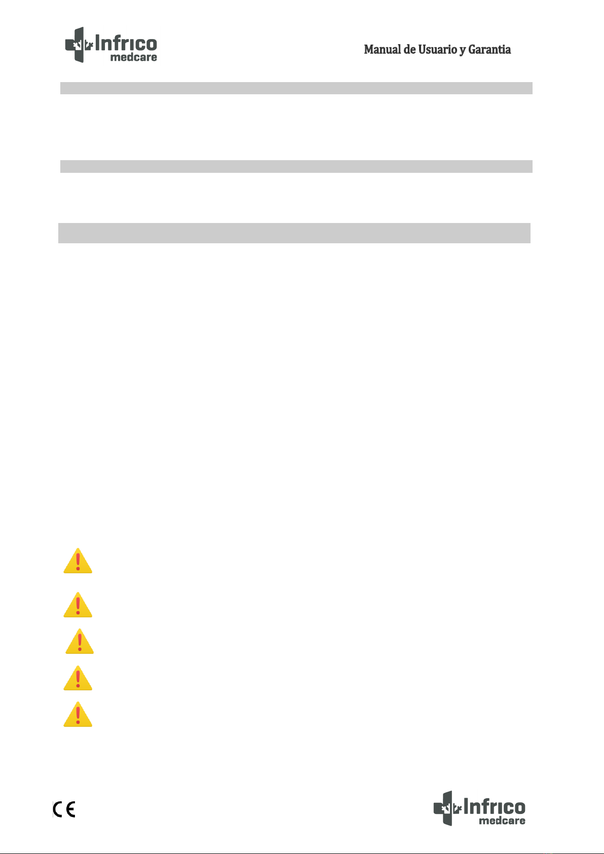
WARNING
MANDATORY
PROHIBITION
BATTERY
EARTHING
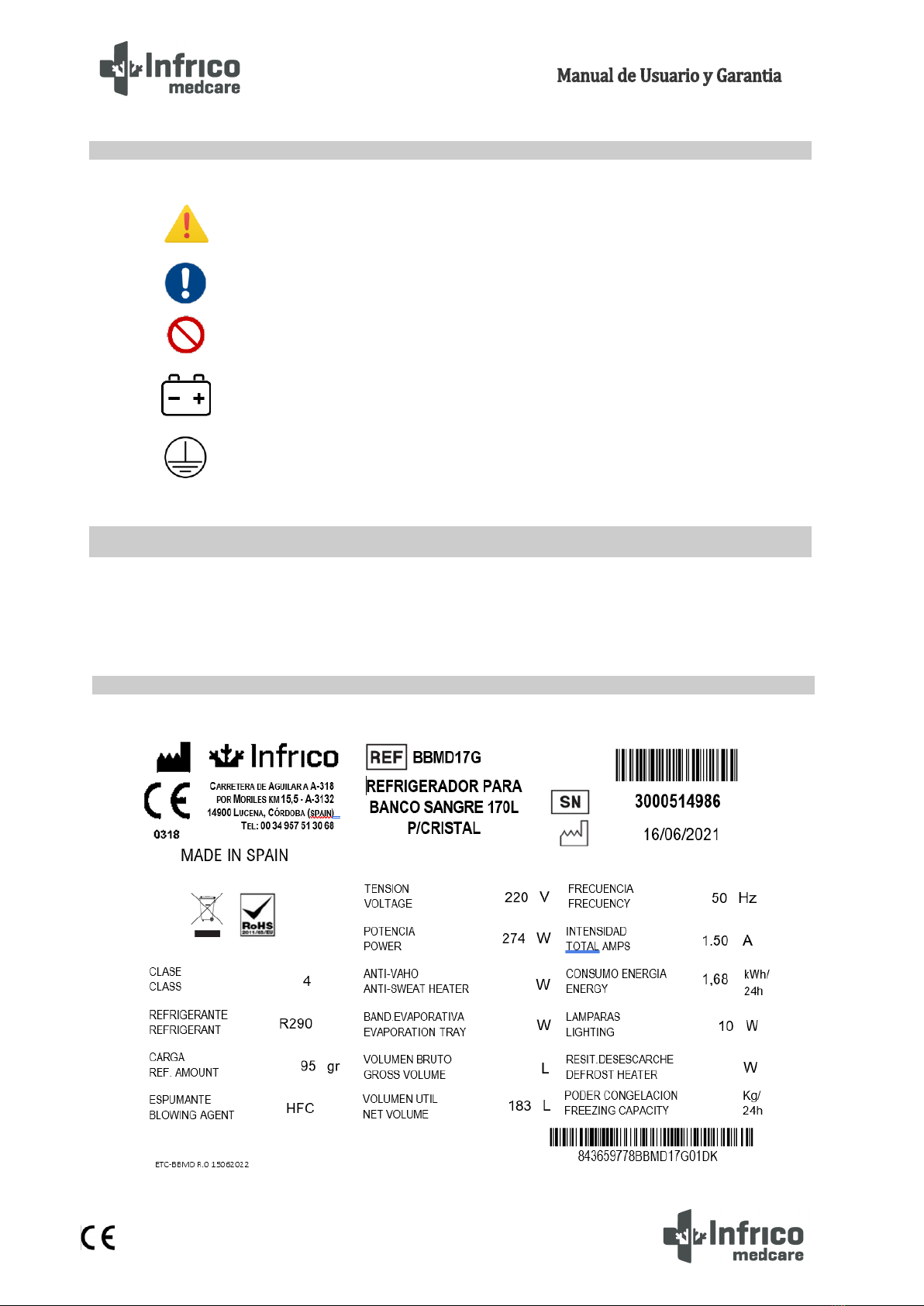
The labelling of our equipment is located in its interior. Its exact location is on the inner left side, at the
top.
2.1 Symbols
3LABELLING
3.1 Technical label
6
MAN-U-BBMD-ES Revision: 00
•All Infrico products are factory tested for quality and performance and are free from defects.
•Upon receipt of the device, it should be carefully inspected for any damage which may have occurred during
transport.
•If any damage to the unit is found, all packaging material must be kept and such damage reported on the
carrier’s “bill of lading”. A claim must be made immediately to the carrier.
•If damage is noticed during or immediately after installation, contact the distributor immediately.
WARNING!: Infrico is not liable for any damages incurred during transport.
This device is intended for indoor use only.
Make certain that the location chosen for the equipment has adequate air circulation to ensure efficient
cooling.
Keep well away from locations close to sources of heat, such as sunny windows, ovens, furnaces,
cookers, as well as direct sunlight where temperatures can reach extreme values. Likewise, do not choose a
location in an area where temperatures fall below 12°C (53.6°F) or exceed 32°C (89.6°F).
Sufficient space must be allowed between the equipment and the side walls so that use can be made of
the 120° door opening lock. Doors must be able to open a minimum of 90° to utilise the maximum available door
width.
The floor of the final location must be strong enough to support the total weight of the device assuming
that the cabinet contains the maximum product load. It must also be level and free from vibration. Reinforce the
floor if necessary.
WARNING!: Do not position the equipment in such a way which renders it difficult to operate on the
disconnect device (power cord plug).
4RECEIPT AND INSPECTION
5INSTALLATION
5.1 Location
5.2 Environmental operating conditions.

7
MAN-U-BBMD-ES Revision: 00
Blood bank refrigerators are designed to be safe under the following conditions.
•Indoor use
•Altitude up to 2000 m (795 mbar)
•Temperature 12ºC to 35ºC (53.6ºF to 95ºF)
•Maximum Relative humidity 65 %
•Mains supply voltage fluctuations never exceeding ±10% of nominal voltage
Blood bank refrigerators are designed to be safe under the following transport conditions.
•Storage Temperature -15ºC (5ºF) to 55ºC (131ºF)
•Relative humidity 20 - 85% (non-condensing)
The equipment leaves the factory on a wooden pallet and packed in easily recyclable cardboard boxes.
The equipment fastened to the wooden base with screws. The screws must be removed beforehand to avoid
damaging the unit when unpacking.
All packaging materials are environmentally friendly and should be reused or recycled. Please actively
contribute to the protection of the environment by demanding recyclable packaging and environmentally
friendly methods of equipment disposal.
WARNING: Infrico does not recommend tipping the device forward, sideways or backwards.
Nevertheless, should this occur, it must be ensured that the unit remains upright for at least 24 hours
before switching it on, so that the compressor oil returns to the compressor.
WARNING!: Connect the equipment to an electrical socket dedicated solely for the device with the
correct voltage. Power fluctuations or incorrect voltage can result in serious damage to the
equipment.
5.3 Environmental conditions for transport and storage.
5.4 Unpacking
5.5 Electrical connection
8
MAN-U-BBMD-ES Revision: 00
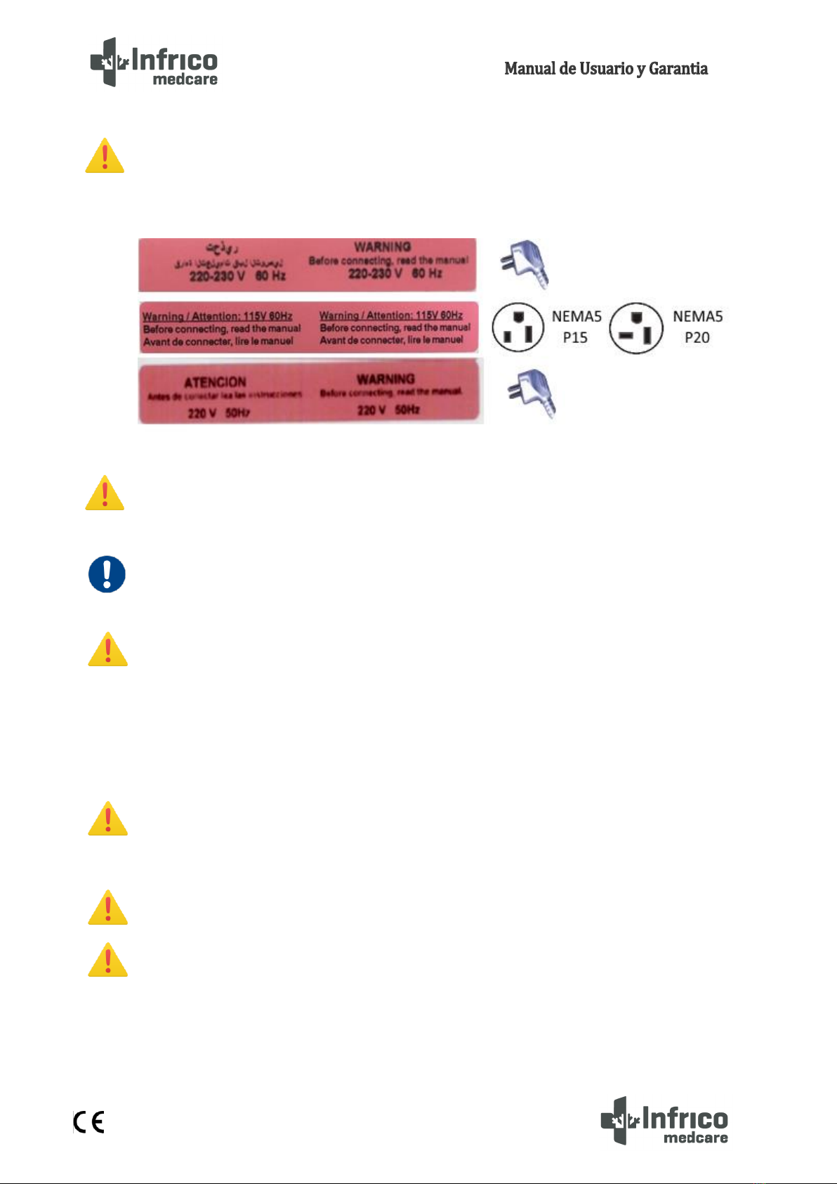
The devices are prepared for mains supply 220-230V 50 Hz, 220-230V 60 Hz or 110-120V 60Hz. The
equipment has a factory installed hose and plug. Check the sticker on the power cord as well as the
technical label. If you do not have a suitable socket, it must be installed beforehand. The means of
isolating the equipment from the mains supply is the plug on the power cord.
WARNING!: For personal safety and equipment operation, this unit must be grounded before use.
Failure to ground may result in personal injury or equipment damage. Always comply with the
National Electrical Code. Do not connect equipment to overloaded power lines.
MANDATORY: The device must be connected to a dedicated circuit. Failure to comply with this
requirement shall void the warranty.
WARNING!: The device unit is designed to cope with a 10%voltage fluctuation of the nominal voltage
specified on the rating plate. Compressor failure due to higher fluctuations automatically voids the
warranty.
Note: The installation of a UPS or other system is recommended to prevent power surges or power
failure.
WARNING!: If the hose or plug is altered in any way, this could pose a serious risk. Any tampering
with these components shall void the warranty.
WARNING!: Infrico does not warrant devices connected to an extension cord.
WARNING!: The power cord can only be replaced by an authorised technical service.
9
MAN-U-BBMD-ES Revision: 00
The device is equipped with a rechargeable lead-acid battery 12V - 12 Ah. Once the equipment has been
installed, it must be connected by activating the switch. This switch is located on the rear of the control panel on
the BBMD65, BBMD80 and BBMD130 models, and on the bottom of the control panel on the BBMD17, BBMD25
and BBMD40 models.
WARNING!: For battery replacement see Section 13.2.
It is very important that the device is perfectly levelled for correct operation, so that the drains drain
correctly, the doors are aligned and the unit is not subjected to undue stress.
These models are supplied from the factory with adjustable feet on the BBMD17, BBMD25 and BBMD40
models, and non-adjustable castors on the BBMD65, BBMD80 and BBMD130 models. If adjustable feet are used,
these must be adjusted until the unit is completely stable and level. If non-adjustable castors are used, it must
be ensured that the floor on which the unit is installed is level by locking the brakes on the front castors.
To check the door gasket seal, follow the steps below:
1. Open the door.
2. Insert a strip of paper between the door gasket seal and the cabinet flange and close the door.
3. Slowly pull the paper strip from the outside. A little resistance should be felt.
4. Repeat this exercise at 10 cm intervals around the door. If the door does not seal properly, it is
necessary to replace the seal or adjust the door.
CAUTION! Door seal integrity is critical for blood bank refrigerators. A loose fitting gasket seal allows
moist air to be drawn into the cabinet, allowing for quicker frost build up on the evaporator coil,
resulting in poor temperature maintenance, longer running time and increased operating costs.
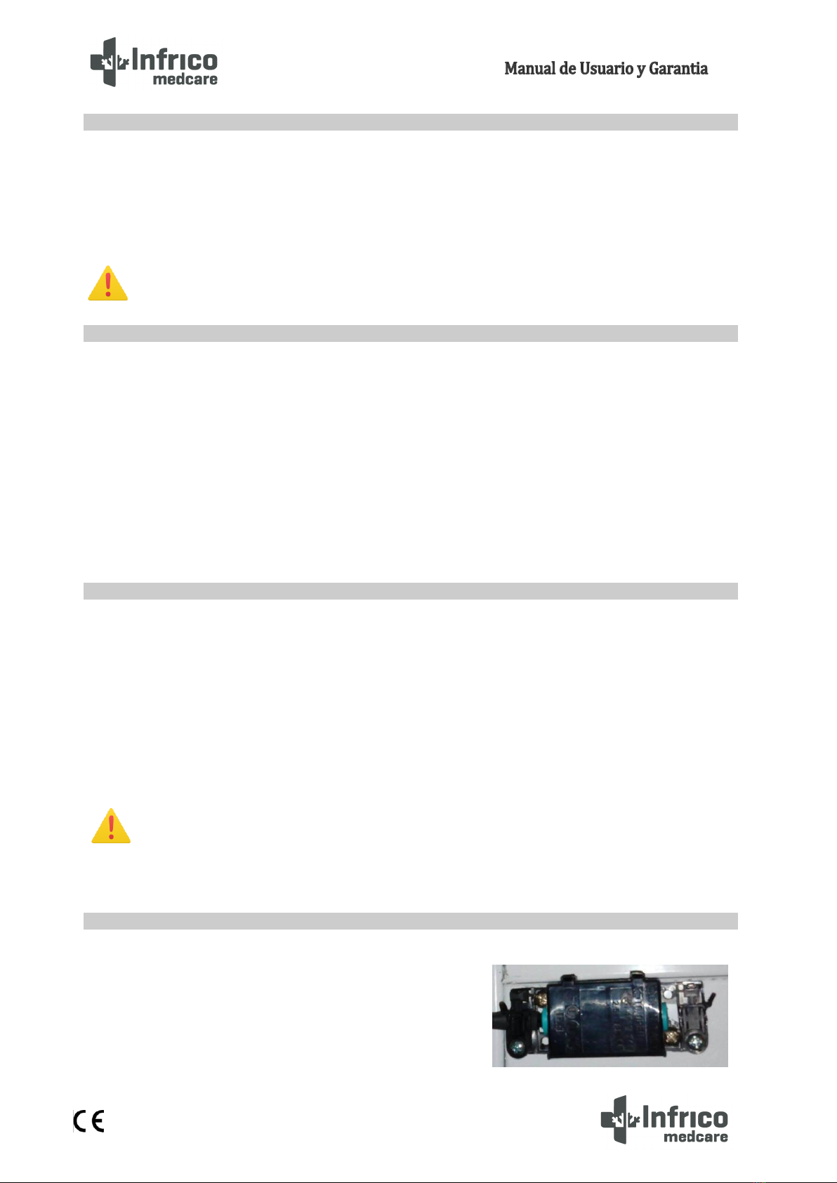
All blood bank refrigerator models have a remote alarm
connection located on the rear of the unit. This is a potential free
contact as per the DIN 58371 Standard.
5.6 Battery
5.7 Levelling
5.8 Door gasket seal
5.9 Remote Alarm Installation
10
MAN-U-BBMD-ES Revision: 00
Before the start up, follow the steps below:
1. Ensure that the unit is free of all wood or cardboard packaging materials, both inside and outside. Do
not remove the grey polystyrene hood of the BBMD80 and BBMD130 models located on the top of the
unit, as it is part of the refrigeration unit. This hood has a sticker on it which specifies that it must not
be removed.
2. Check the position of the stainless steel drawers. If it is wished to adjust the height of the drawers,
follow the instructions in Section 6.3.
3. Verify that the unit is connected to a dedicated socket.
Prior to start up, clean and disinfect the cabinet to remove any metal, plastic, stickers or debris.
Use water with a neutral detergent and dry properly.
CAUTION! Do not use a brush, acid, thinner, laundry soap, washing powder or boiling water for
cleaning.
These substances cause damage to the surface of both painted and stainless steel, or failure of plastic
and rubber components. Likewise, do not clean plastic and rubber components using a volatile
material.
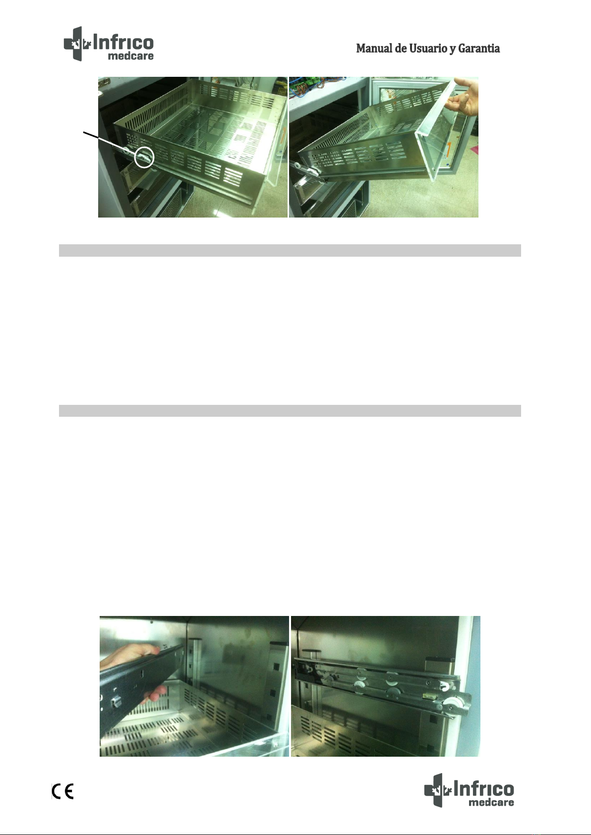
To remove the drawers complete the following steps:
1. Pull the drawer towards you until the sliding guides are fully extended.
2. Press on the back of the side clips to unlock the drawer lock.
3. Lift the front of the drawer and pull it backwards to remove it.
5.10 Final Verification
5.11 Cleaning and Disinfection
6DRAWERS (OPTIONAL)
6.1 Removing Drawers
11
MAN-U-BBMD-ES Revision: 00
To reinstall the drawers complete the following steps:
1. Insert the drawer at an angle of approximately 45° into the side sliding guides, once on its
sliding guide lay flat.
2. Press down on the front of the side clips to lock the drawer lock.
3. Insert the drawer as far as it will go.
The drawer sliding guides are height adjustable. Sliding guides can be positioned in the vertical slots
which are spaced at fixed intervals.
To change the position of the drawer sliding guides, complete the following steps:
1. Pull the front of the drawer sliding guide upwards until the front tab pops out of its casing.
2. Then pull the sliding guide forward until the rear tab pops out of its casing.
3. Change the height to one’s liking by following the steps in reverse to reposition the sliding
guide.
6.2 Reinstalling Drawers
6.3 Changing drawer position
2
12
MAN-U-BBMD-ES Revision: 00
By " operating mode ", reference is made to the following modes:
o"ON" mode (the device is switched on and the controllers can be
switched on)
o"Stand-By" mode (the device is switched on and the controllers are
switched off)
o"OFF" mode (the device is not switched on)
Understanding "Turn on" as switching from "Stand-By " mode to "ON" and
"Turn off" modes and switching from the "ON" mode to the " Stand-By" mode.
Each time the device is connected to the power supply, it shall return to its original mode at the time of
disconnection.
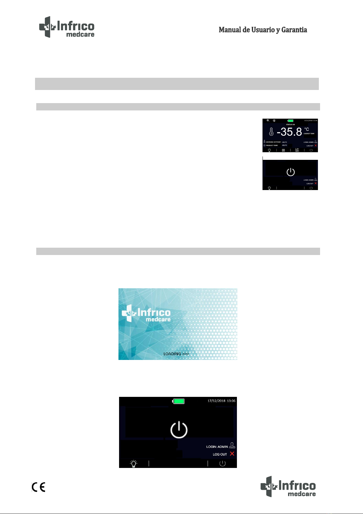
Undertake the following:
1.- Connect the device to the power supply: A "LOADING" message will be displayed for 10 seconds.
2.- The device will be in "Stand-By" mode and the date and time will be shown on the display. In the
event that the controller is stored for a time longer than the capacity of the backup battery, the date and time
will have to be reset.
7DIGITAL PLUS CONTROL
7.1 Preliminary notes
7.2 First switching on of the Device
Modo “ON”
Modo “Stand-By”

13
MAN-U-BBMD-ES Revision: 00
3.- Press the ON / STAND-BY icon: The start-up screen will appear as shown in the picture.
4.- Set the device according to the following sections.
5.- Connect the equipment's battery.
To switch the device on or off, undertake the following:
1.- Ensure that the keyboard is not locked and that no procedure is underway.
2.- Press the ON/STAND-BY icon.
When the device is switched on, during normal operation, the following information will be displayed
on the home screen:
- Time / Date
- Battery charge status
- Product/cabinet temperature
- Setpoint
- Equipment status icons:
7.3 Switching the device on/off
7.4 The display screen
14
MAN-U-BBMD-ES Revision: 00
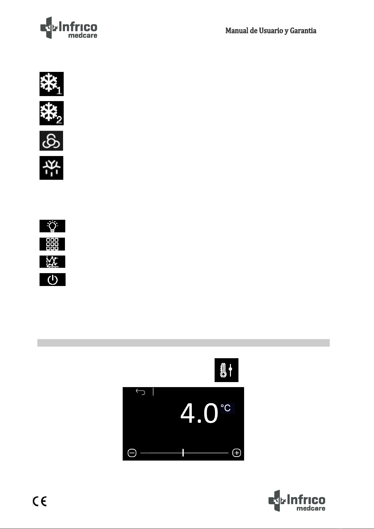
Compressor power on icon
Compressor power on icon 2
Evaporator fan on icon
Defrost Power On icon
- Function keys:
Switches the light on and off
Access to main menu
Access to real time graph
Places the equipment in “Stand-By”mode
These icons are greyed out when disabled for the currently logged in user or the relative function is not
enabled.
Click through the main menu by clicking on Setpoint setting .
7.5 Setpoint Adjustments
15
MAN-U-BBMD-ES Revision: 00
To view the battery status, press the icon on the main screen, or the icon once within the
main menu.
-In case of smooth operation, the voltage provided by the battery shall be displayed.
-In case of absence of the battery or in the presence of any anomaly, the "Battery problem"
message shall be displayed.
If there are communication problems with the battery-charger, the "Information not present" message
shall be displayed.
The “Battery Status”option can be enabled according to parameters or if the user logged in at that
moment is enabled to display the battery status.
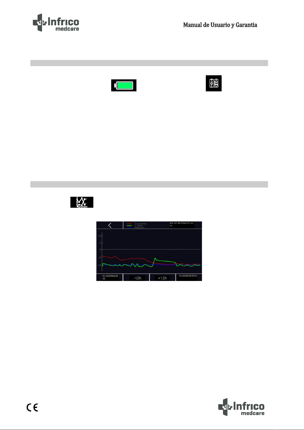
Press the icon to display the temperature graph of the cabinet sensor and the product (the
latter if enabled by the related parameter).
The controller displays in real time the graph of the temperatures of the last 12 hours (from the time of
the request (now 0) to the time -12) (.
The three lines plotted are related to:
- Product sensor temperature in blue
- Cabinet sensor temperature in green
- Working setpoint in red
The x-axis has a vertical striped bar to specify the hours, while at the bottom left the time and date of
the first record displayed will be specified, while at the bottom right is the time of the last data shown on the
graph.
The ordinate axis (y-axis) on the other hand is the minimum and maximum value to be displayed in the
window so that the data are all within the window.
7.6 Battery Status
7.7 Temperature graph
16
MAN-U-BBMD-ES Revision: 00
By means of the 2 navigation keys it will be possible:
-12h: Shifts from time -12 to time -24 (with respect to time 0 of the request). And so on. If the data is
not present, the “NO DATA”message will appear specifying the absence of data recorded at that time.
+12h: Return with the graphs to hour 0.
This function can be accessed manually, irrespective as to whether the keypad is locked. The light is
switched on/off after pressing the "light" icon and after a door opening/closing. This function is located
at the bottom left of the display.
To shut off the audible alarm, proceed as follows:
1.- Ensure that no process is underway.
2.- Press the following icon on the main screen
When the icon is pressed, then the previous icon becomes the next icon .
To log in users, click on the icon.
The controller has a backup battery, which is connected to a battery charger. During the time the
battery lasts, data related to product sensors, alarms and other events can be stored.
7.8 Interior light Switching On/Off
7.9 Mute Alarm
7.10 User Login
7.11 Battery Operation During Power Failure

17
MAN-U-BBMD-ES Revision: 00
Press the icon to access the main menu:
Once the main menu is accessed, it is possible to display and modify different options. Such as the
following:
Pressing the icon enables the edit mode of the unit's working temperature point (Setpoint).
Press the icon to start a manual defrost cycle.
8ADJUSTMENTS
8.1 Main Menu
8.1.1 Setpoint Adjustments
8.1.2 Defrost Start Up

18
MAN-U-BBMD-ES Revision: 00
Press the icon to check the battery status.
In case of smooth operation, the voltage provided by the battery shall be displayed.
In case of absence of the battery or in the presence of an anomaly, the "Battery problem" message shall be
displayed.
If there are communication problems with the battery-charger, the " Information not present " message
shall be displayed.
The “Battery Status”option is enabled if the currently logged in user has permissions to view the
battery status.
Press the icon to access the "Alarm/Data Historical Record" submenu, which consists of the
following functions/screens:
Press the icon to access the alarm display mode. It is possible to record up to 30 alarms with
their related information. When accessed, the screen displays the information related to the last alarm that
occurred, showing the following alarm data:
- Recorded alarm number
- Type of alarm.
- Date/time of start and end date of alarm
8.1.3 Battery Status
8.1.4 Alarm/Data Historical Record Menu
8.1.4.1 Alarms List
This manual suits for next models
12
Table of contents
Other Infrico Commercial Food Equipment manuals


Popular Commercial Food Equipment manuals by other brands


Diamond
Diamond AL1TB/H2-R2 Installation, Operating and Maintenance Instruction

Salva
Salva IVERPAN FC-18 User instructions

Allure
Allure Melanger JR6t Operator's manual

saro
saro FKT 935 operating instructions

Hussmann
Hussmann Rear Roll-in Dairy Installation & operation manual

Cornelius
Cornelius IDC PRO 255 Service manual

Moduline
Moduline HSH E Series Service manual

MINERVA OMEGA
MINERVA OMEGA DERBY 270 operating instructions

Diamond
Diamond OPTIMA 700 Installation, use and maintenance instructions

Diamond
Diamond G9/PLCA4 operating instructions

Cuppone
Cuppone BERNINI BRN 280 Installation

Arneg
Arneg Atlanta Direction for Installation and Use