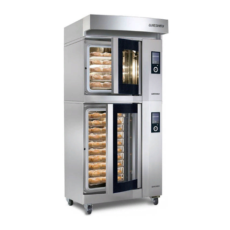
WIESHEU Euromat 64 L User manual

Original Operating Instructions EN
Euromat 64 S/L
In-Store Baking Oven

Page 2 Euromat 64 V16-01 9401-110-001-EN
Contents
1 Explanation of the User Information 3
1.1 Legends 4
1.1.1 Degrees of danger and symbols 4
1.1.2 Symbols in the described actions 4
1.1.3 Safety information and symbols 5
1.2 Type plate 5
1.2.1 Device features and options 6
1.3. EU Declaration of Conformity 7
2 Product Description 9
2.1 Function/overview 9
2.2 Intended Use 9
2.3 Reasonably Foreseeable Misuse 9
2.4 Liability 9
2.5 Technical specications 10
2.6 Risk of injury/residual risks 12
2.6.1 Obligation of the customer 12
2.6.2 Obligation of the sta 12
2.6.3 General risk of accidents 12
2.6.4 Danger of re/explosion 12
2.6.5 Danger from contact with electrics 13
2.6.6 Danger of burns 13
2.6.7 Water damage 13
2.6.8 Danger of non-ionising radiation 13
2.6.9 Danger of technical damage 14
3 Transportation and Setup 14
3.1 Transporting the appliance/combined appliance 14
3.2 Unpacking the appliance/combined appliance 14
3.2.1 Dismounting the transport pallet 15
3.3 Dismounting/mounting the combined appliance 15
3.4 Place of installation and surroundings 17
3.5 Place of installation and distances 17
3.5.1 Free space next to, below and above the appliance/combined appliance 17
3.5.2 Free space in front of and behind the appliance/combined appliance 18
3.5.3 Distances to sources of heat 18
3.5.4 Distances to safety equipment 18
3.5.5 Appliance/combined appliance with enclosure 19
3.5.6. Appliance ID 19
3.6 Connections on-site 20
3.6.1 Electrical connection 20
3.6.2 Plumbed-in water connection 21
3.6.3 Waste water connection 22
3.6.4 Exhaust air connection 23

Page 3
Euromat 64 V16-01 9401-110-001-EN
3.7 Commissioning 23
3.7.1 Inspections to be carried out before commissioning 24
4 Operation 25
4.1 Opening/closing the door 25
4.2 Inserting/removing bakery products 26
4.3 Setting the baking parameters 26
4.4 Removing/installing the tray frames 26
5 Cleaning 27
5.1 General cleaning work 27
5.2 Cleaning agents 28
5.3 Cleaning instructions and cleaning agents 29
5.4 Descaling 31
6 Servicing 31
6.1 General maintenance work 31
6.2 Faults/causes/remedies 32
7 Disposal 33
8 Copyright 33
1 Explanation of the User Information
The equipment is a machine in the sense of Machine Directive 2006/42/EC. This user information provides
information on intended and safe operation and contains important instructions on how to operate the device
safely, appropriately, and economically. Read the instructions before starting to use the equipment.
Depending on the model, the illustrations may dier from the product. The control’s operating Instructions
supplement this user information. Depending on the version of the device, it is completed by the user infor-
mation of the options.
Paying attention to the user information helps to avoid danger and to optimise and speed up process ows.
It helps to minimise downtimes and the costs of repairs and to increase the device’s reliability and extend its
service life.
This documentation applies to the following device types and their options:
Euromat 64 S Item number 2500-*-********
Euromat 64 L Item number 2600-*-********

Page 4 Euromat 64 V16-01 9401-110-001-EN
1.1.2 Symbols in the described actions
■Indicates an action
▪Indicates a lower-level action or an additional action that must be carried out beforehand
→Indicates the result of an action
●Indicates a listing
○Indicates a lower-level listing
Symbol Declaration of Conformity
Danger
An extremely dangerous situation in which ignoring the safety information will
lead to death or serious injury.
Warning
A dangerous situation in which ignoring the safety information can lead to death
or serious injury.
Caution
A dangerous situation in which ignoring the safety information can lead to minor
injury.
Notice
Indicates actions that can lead to damage to property.
Information
Indicates information that makes it easier to handle and work on the product or
shows an additional benet.
DANGER
CAUTION
WARNING
NOTICE
INFORMATION
This user information is an integral part of the product and must be kept in close
proximity to the machine, and stored such that it is easily accessible for operating
personnel to consult it at all times. Everybody who works with the machine must
have completely read the user information before starting work.
INFORMATION
1.1 Legends
1.1.1 Degrees of danger and symbols

Page 5
Euromat 64 V16-01 9401-110-001-EN
Symbol Declaration of Conform-
ity
Symbol Declaration of Conform-
ity
Warning of a hazardous
location
Warning of a crushing
hazard
Warning of a dangerous
electrical voltage
Warning of irritants
Warning of a hot surface Warning of a tipping
hazard
Warning of a re hazard Warning of a risk of
scalding
Equipotential bonding
Check before starting
work
Disconnect from mains
Use hand protection Use eye protection
Electrical connection Exhaust air connection
Fresh water connection Waste water connection
Before using, read the
user information
Before starting work, read
the service information
1.1.3 Safety information and symbols
1.2 Type plate
Pos. Bezeichnung
10 Type
20 Serial number
30 Voltage (V)
40 Output (kW)
50 IP protection class
60 Water pressure (kPa)
70 Year of production/month
80 Frequency (N/Hz)
WIESHEU GmbH
Daimlerstraße 10 71563 Aalterbach
Telefon +49 (0)7148 1629-0
Service Hotline: +49 (0)7148 1629-400
Artikel:
Item:
Seriennr.:
Serial-no:
Spannung:
voltage:
Baujahr:
Prod.year:
Frequenz
frequency:
Leistung:
connected load:
Wasserdruck:
water pressure:
IP-Schutzart:
IP-code:
10 50
20 60
30 70
40 80
The type plate contains the most important information about
the device. The type plate is located on the right- or left-hand
side of the device (depending on the model).

Page 6 Euromat 64 V16-01 9401-110-001-EN
Item Feature Option Identi-
er
1Classication
Standard A
Nostalgia N
2Trays
4 shelves A
5 shelves B
8 shelves Y
10 shelves Z
3Control unit
IS 600 E B
4Water
connection
Fixed water connec-
tion
B
5Steaming
Pipe steaming B
Cascade passive D
6Cleaning
none A
LiquidClean (LC) B
UltraClean (UC) C
LC + UC D
7Door
Door stop right A
Door stop left SV+PIN B
Door stop right E
Door stop left SV+PIN F
8Version
Heating power 9 kW A
Heating power 7 kW B
Heating power 6 kW C
9Vario
Individual appliance A
Vario at top B
Vario at bottom C
1.2.1 Device features and options
Each device is identied by an item number. You can nd it on the device's type plate (10). The item number
is composed of a xed combination of numbers (A) and a variable combination of letters (B).
You can derive the device type and its size from the combination of numbers.
The 9-letter combination of letters denes the exact composition of all the possible options. Using the table,
you can read o the article number on the type plate.
The star (*) special character can be located at dierent positions. In these cases, the special character is a
placeholder for an option that does not need to be identied explicitly.
Example:
AB
2500-A-BBBBAEAA
12 4 63 5 7 8 9
Door stop right
Heating 9 kW
Individual
appliance
Euromat 64 S
Cleaning: None
Pipe steaming
Plumbed-in water connection
Control unit: IS 600 E
Trays: 5
Version: Standard
2500-*-A***D***
2 6

Page 7
Euromat 64 V16-01 9401-110-001-EN
1.3. EU Declaration of Conformity
Directive on Machinery 2006/42/EC
In accordance with Appendix I No. 1.5.1. of Directive on Machinery 2006/42/EC, the aims of low-volt-
age directive 2014/35/EC have been complied with.
EN 12100:2010 EN 14159:2008
EN 13732-1:2008 EN 1672-2:2005 + A1:2009
EN 349:1993 + A1:2008 EN 60335-1:2012
EN 60335-2-42:2003 + Corr. :2007 + A1:2008 +
A11:2012
The manufacturer
WIESHEU GmbH
Schleifwiesenstraße 27
71723 Großbottwar
Germany
hereby declares that the appliances described below conform to the relevant Community harmonisation leg-
islation both in its basic design and construction as well as in the version marketed by us:
Other applicable standards and specications
EN 82079-1:2012
Product line Euromat
Description of appliance Convection oven
Appliance type as described in the user information
and the following appliance types
Euromat 64 S
Item No. 2500-*-*BBB**** / 2500-*-*BBD**** / 2500-*-*BB***A*
2500-*-*BB***B* / 2500-*-*BB***C*
Name and address of the Documentation Ocer WIESHEU GmbH
Technical Documentation Department
Schleifwiesenstraße 27, 71723 Großbottwar
Germany
This declaration will cease to be valid if any modications are made to the appliance without our express
approval.
2014/30/EU EG-Directive on Electromagnetic Compatibility
EN 55014-1:2006 + A1:2009 + A2:2011 EN 61000-3-3:2013
EN 55014-2:1997 + Corr.:1997 + A1:2001 +
A2:2008
EN 61000-3-12:2011
EN 55022:2010

Page 8 Euromat 64 V16-01 9401-110-001-EN
1.3. EU Declaration of Conformity
Directive on Machinery 2006/42/EC
In accordance with Appendix I No. 1.5.1. of Directive on Machinery 2006/42/EC, the aims of low-volt-
age directive 2014/35/EC have been complied with.
EN 12100:2010 EN 14159:2008
EN 13732-1:2008 EN 1672-2:2005 + A1:2009
EN 349:1993 + A1:2008 EN 60335-1:2012
EN 60335-2-42:2003 + Corr. :2007 + A1:2008 +
A11:2012
The manufacturer
WIESHEU GmbH
Schleifwiesenstraße 27
71723 Großbottwar
Germany
hereby declares that the appliances described below conform to the relevant Community harmonisation leg-
islation both in its basic design and construction as well as in the version marketed by us:
Other applicable standards and specications
EN 82079-1:2012
Product line Euromat
Description of appliance Convection oven
Appliance type as described in the user information
and the following appliance types
Euromat 64 L
400V 50Hz
Item No. 2600-*-*BBB**** / 2600-*-*BBD**** / 2600-*-*BB***A*
2600-*-*BB***B* / 2600-*-*BB***C*
Name and address of the
Documentation Ocer
WIESHEU GmbH
Technical Documentation Department
Schleifwiesenstraße 27, 71723 Großbottwar
Germany
This declaration will cease to be valid if any modications are made to the appliance without our express
approval.
2014/30/EU EG-Directive on Electromagnetic Compatibility
EN 55014-1:2006 + A1:2009 + A2:2011 EN 61000-3-11:2000
EN 55014-2:1997 + A1:2001 + A2:2008 EN 61000-3-12:2011
EN 55022:2010

Page 9
Euromat 64 V16-01 9401-110-001-EN
2 Product Description
2.1 Function/overview
Using the WIESHEU oven, it is possible to heat and bake commercial bakeable goods.
2.2 Intended Use
The device is technical equipment. It is not intended for use in the home.
The device is designed exclusively for baking commercial bakeable goods.
The device is intended for indoor use only.
With the “safety lock” option, the device can be installed in the food retail sector.
Optional enhancements or modications to the device must only be implemented in designs approved by
WIESHEU GmbH.
Any other enhancements and/or modications to the device are not permitted.
Any other usage extending beyond this is not regarded as intended usage.
WIESHEU GmbH is not liable for damages resulting from such unintended use.
2.3 Reasonably Foreseeable Misuse
The device is not intended to be located in cold stores. Complete functionality can only be guaranteed at
temperatures of a minimum of +8 and a maximum of +40 °C.
The device is not intended for use in trains or mobile shops, on ships or outdoors.
The device is not intended for drying or curing objects.
The device is not suitable for heating liquids or food which will liquefy.
2.4 Liability
The customer and operating personnel are obliged to observe the instructions in the user information.
The general and regional accident prevention guidelines of the responsible trade associations must be com-
plied with.
WIESHEU GmbH assumes no liability for damage which occurs as a result of incorrect or negligent opera-
tion, working with the wrong operating parameters, servicing or maintenance or non-intended use. This also
applies to changes, enhancements and modications to the combined unit. Any factory guarantee will thus
become null and void.
Only use spare parts approved by the manufacturer.
WIESHEU GmbH shall not accept liability for damage resulting from the use of non-approved spare parts.
The below-mentioned work should only be carried out by authorised
service partners/service technicians of WIESHEU GmbH:
• Installation
• Assembly
• Commissioning
• Maintenance/service
NOTICE

Page 10 Euromat 64 V16-01 9401-110-001-EN
2.5 Technical specications
The maximum number of trays the appliance can hold is specied in the technical specications.
Regardless of the number of trays indicated, the device can be operated with fewer trays. The settings of the
baking parameters should be adjusted accordingly when required.
The maximum load weight of 5 kg per tray must not be exceeded.
Item No. 2500-*-******C* 2500-*-******B* 2500-*-******A*
Appliance designation Euromat 64 S Euromat 64 S Euromat 64 S
Designation Convection oven Convection oven Convection oven
Version AC 380 - 415 V 50Hz AC 380 - 415 V 50Hz AC 380 - 415 V 50Hz
Control unit IS 600 E IS 600 E IS 600 E
Door Double-glazed Double-glazed Double-glazed
Door option Door stop right/left Door stop right/left Door stop right/left
Steaming Pipe steaming
Cascade passive
Pipe steaming
Cascade passive
Pipe steaming
Cascade passive
Width mm 930 930 930
Depth mm 1020 1020 1020
Height mm 575
695 1)
575
695 1)
575
695 1)
Weight kg 110
120 2)
110
120 2)
110
120 2)
Number of chambers ----- ----- -----
Size of number of shelves mm 4/5 × 600 × 400 4/5 × 600 × 400 4/5 × 600 × 400
Fuse A 3 × 16 3 × 16 3 × 16
Current
consumption
[380V]
[400V]
[415V]
A
A
A
8.8
9.2
9.6
10.1
10.7
11.1
12.9
13.6
14.1
max. permissible leakage current
according to DIN EN 60335-1
mA 9,6 10 10
Chamber heating kW ----- ----- -----
Heating DE kW ----- ----- -----
Connected load [380V]
[400V]
[415V]
kW
kW
kW
5.8
6.4
6.9
6.7
7.4
8.0
8.5
9.4
10.1
Heating kW 6.0 7.0 9.0
Heating of cascade kW ----- ----- -----
Motor kW 0.2 0.2 0.2
Protection class code IP X3 X3 X3
Temperature range °C 30 - 250 30 - 250 30 - 250
Ambient temperature °C +10 - +40 +10 - +40 +10 - +40
Ambient humidity %rH 30 - 60 30 - 60 30 - 60
Water connection ″3/4 3/4 3/4
Water pressure kPa 150 - 600 150 - 600 150 - 600
Waste water connection: mm Ø 50 50 50
Exhaust connection mm Ø 50 50 50
Condensate connection mm Ø 15 15 15
Workplace-specic sound emis-
sion value
dB (A) < 70 < 70 < 70
1) With ProClean option 2) With cascade option

Page 11
Euromat 64 V16-01 9401-110-001-EN
1) With ProClean option 2) With cascade option
Item No. 2600-*-******C* 2600-*-******B* 2600-*-******A*
Appliance designation Euromat 64 L Euromat 64 L Euromat 64 L
Designation Convection oven Convection oven Convection oven
Version AC 380 - 415 V 50Hz AC 380 - 415 V 50Hz AC 380 - 415 V 50Hz
Control unit IS 600 E IS 600 E IS 600 E
Door Double-glazed Double-glazed Double-glazed
Door option Door stop right/left Door stop right/left Door stop right/left
Steaming Pipe steaming
Cascade passive
Pipe steaming
Cascade passive
Pipe steaming
Cascade passive
Width mm 930 930 930
Depth mm 1020 1020 1020
Height mm 975
1095 1)
975
1095 1)
975
1095 1)
Weight kg 160
180 2)
160
180 2)
160
180 2)
Number of chambers ----- ----- -----
Size of number of shelves mm 8/10 × 600 × 400 8/10 × 600 × 400 8/10 × 600 × 400
Fuse A 3 × 32 3 × 32 3 × 32
Current
consumption
[380V]
[400V]
[415V]
A
A
A
17.0
17.9
18.6
20.6
21.2
22.0
25.6
27.0
28.0
max. permissible leakage current
according to DIN EN 60335-1
mA 10 10 10
Chamber heating kW ----- ----- -----
Heating DE kW ----- ----- -----
Connected load [380V]
[400V]
[415V]
kW
kW
kW
11.2
12.4
13.3
13.3
14.7
15.7
16.9
18.7
20.1
Heating kW 12.0 14.0 18.0
Heating of cascade kW ----- ----- -----
Motor kW 0.4 0.4 0.4
Protection class code IP X3 X3 X3
Temperature range °C 30 - 250 30 - 250 30 - 250
Ambient temperature °C +10 - +40 +10 - +40 +10 - +40
Ambient humidity %rH 30 - 60 30 - 60 30 - 60
Water connection ″3/4 3/4 3/4
Water pressure kPa 150 - 600 150 - 600 150 - 600
Waste water connection: mm Ø 50 50 50
Exhaust connection mm Ø 50 50 50
Condensate connection mm Ø 15 15 15
Workplace-specic sound emis-
sion value
dB (A) < 70 < 70 < 70

Page 12 Euromat 64 V16-01 9401-110-001-EN
2.6 Risk of injury/residual risks
This device has been produced by WIESHEU GmbH according to the latest technological developments.
All appliances that leave the factory have been subjected to thorough testing.
Nevertheless, if the appliance is used improperly, hazards to life and limb of the user or a third party may
result, or the appliance or other assets may be damaged.
General safety instructions are summarized in this chapter. Specic safety instructions are described in the
sections where operators are directly confronted with risks.
The following safety instructions must be understood as a supplement to already applicable national accident
prevention regulations and laws.
Existing accident prevention regulations and laws must be adhered to in any case.
All appliances must be installed categorically in accordance with the valid, local safety regulations.
2.6.1 Obligation of the customer
The customer is obliged to only allow people to work with the device who are acquainted with the funda-
mental instructions regarding work safety and accident prevention and have been instructed in handling the
device. Operating companies are obliged not to allow people to work with the appliance who suer from im-
pairments with respect to their physical, mental, and sensory capabilities. The youth work protection act and
the EU Directive 97/33/EG are to be observed and complied with.
You must supervise children below the age of 14 to ensure that they do not play with the device.
2.6.2 Obligation of the sta
Before starting work on the appliance, everybody who works with it must have read this user information, be
familiar with its contents and pay attention to it. The persons conrm this by their signature.
Danger of re!
There is a danger of re if the device overloads electrically.
The fuse protection of the plug socket must be ensured.
Do not attach foil, paper, stickers etc. to the device.
Remove all protective sheeting from the device before initial commissioning.
Do not store items or foreign objects in, on, or near the device.
Never heat up alcoholic items or items that are ammable or explosive!
2.6.4 Danger of re/explosion
2.6.3 General risk of accidents
Comply with the general accident prevention regulations when working with and
on the appliance.
WARNING
CAUTION

Page 13
Euromat 64 V16-01 9401-110-001-EN
2.6.7 Water damage
The water tap installed by the customer near the device may only be turned on if
the device is running and must be turned o again afterwards. The ow pressure
of the water may not exceed the pressure stated on the type plate. If necessary,
a pressure regulator must be installed by the customer.
2.6.5 Danger from contact with electrics
Danger of electric shock!
A defective appliance can cause an electric shock.
The electrical connection and any work on the electrical equipment of the device
must only be carried out by an electrician trained in the workings of this particu-
lar product, and in full compliance with industry standards and regulations.
Protect all electrical assemblies from damp, moisture and dust. Important func-
tions, e.g. safety circuits can fail and lead to people being injured and appliance
parts being damaged.
Only use the device when it is in technically perfect condition. Before starting
work, check the device for damage.
Remove the mains plug if damaged! All parts must be correctly assembled and
full all conditions to ensure problem-free operation.
2.6.6 Danger of burns
Risk of burning!
To prevent scalding from heated liquids, do not push containers into the device
with liquids or with food that will liquefy when heated.
There is a danger of being burnt by hot liquids and steam.
Do not open the door while the program is running.
Hot steam exits through the exhaust connection on the back of the device. Set
the device up such that no personal injury or material damage can occur as a
result of exiting steam. Shut o the construction-side water supply immediately
if the solenoid valve is defective, or if the steam injection valve is permanently
open. Any other operation is prohibited.
2.6.8 Danger of non-ionising radiation
Non-ionising radiation is not generated specically; it is emitted due to the tech-
nology by the electrical resources (e.g. electric motors, power lines or solenoid
coils).
Apart from this, the appliance does not have any powerful permanent magnets.
If a safety distance of at least 30 cm is kept between the eld source and the
implant, it is possible to virtually rule out completely active implants (like pace-
makers or debrillators, for example) being aected.
INFORMATION
DANGER
CAUTION
NOTICE

Page 14 Euromat 64 V16-01 9401-110-001-EN
3 Transportation and Setup
3.1 Transporting the appliance/combined appliance
Transport the entire combined appliance to the set up location and position.
If the combined appliance cannot be transported to the installation location as a whole, then the individual
appliances must be removed from the combination. Pay attention to all the information in the chapters enti-
tled “Unpacking the appliance/combined appliance” and “Dismantling/mounting the appliance/the combined
appliance”.
The appliance/combined appliance is packed onto a transport pallet at the factory. Remove all foil and card-
board packaging. Comply with packaging disposal regulations. The transport pallet is reusable and can be
sent back to the manufacturer.
Technical damage!
Always transport the device or the combined unit vertically; otherwise, damage
can be caused.
The device or combined unit is packed on a transport pallet.
The transport pallet can be driven underneath using a lifting truck.
Danger of crushing!
Do not stand under or reach under raised, suspended loads!
Danger of tilting!
When transporting with a transport pallet, it is important to ensure that the pallet
is positioned completely underneath the lifting truck. Secure the pallet with the
appliance/combined appliance onto the lifting truck prior to lifting. Use a suitable
lashing strap.
The appliance/combined appliance may be moved a maximum distance of three
metres for servicing, maintenance and cleaning purposes. Only transport the
appliance/combined appliance in conjunction with the transport pallet and with
a suitable lifting truck.
The device’s door is made of glass and there is a risk of the glass breaking.
Carefully check for any glass damage when unpacking and wear appropriate
protective gloves to prevent cuts.
3.2 Unpacking the appliance/combined appliance
WARNING
CAUTION
NOTICE
NOTICE
Technical damage!
The Euromat is equipped with a frequency converter which can be damaged by
power surges. After disconnecting the mains plug from the power supply, wait
1 minute until all components have discharged fully. Only then reconnect the
mains plug to the power supply.
NOTICE
2.6.9 Danger of technical damage

Page 15
Euromat 64 V16-01 9401-110-001-EN
3.2.1 Dismounting the transport pallet
Tools and aids needed for dismounting:
■A cordless screwdriver
■A bit set for star torx screws
■Platform truck
■Working gloves
C
A
B
D
B
E
■Undo the 8 screws from the crossbeam (A).
■Remove the crossbeam (A).
■Remove the 3 screws from the wooden blocks (B).
■Remove the wooden blocks(B).
■Remove the screws (C) from the inside of the pallet.
■Remove the side panels (D) on the right and the left.
■Push the lifting truck under the pallet.
■Raise the appliance/combined appliance.
■Place the wooden blocks (B) under the casters/feet of the device.
■Lower the appliance/combined appliance carefully onto the wooden
blocks (B).
■Using the lifting truck, remove the inside part (E) of the pallet.
■Run the lifting truck under the appliance/combined appliance.
■Raise the appliance/combined appliance.
■Remove the wooden blocks(B).
■Carefully lower the appliance/combined appliance.
■Remove the wood screws from the pallet.
■Dispose of the pallet material in an environmentally friendly way.
Disassembly can be carried out by one person.
INFORMATION
3.3 Dismounting/mounting the combined appliance
If a combined appliance cannot be transported to the installation location as a whole, then the individual
appliances must be removed from the combination. Disassemble the waste water pipe/exhaust air pipe. Use
suitable slinging gear when lifting and carrying the individual elements. For example scissor lift, lifting truck
with narrow forks, carrying straps, carrying aid, lashing straps.

Page 16 Euromat 64 V16-01 9401-110-001-EN
Dismounting/mounting the combined appliance continued
Component Description
D= Dismounting/M= Mounting
Support
material
Figure
Steam
reducer
D.: Loosen the screws at the rear of the steam
reducer. Push the steam reducer back-
wards.
Take o the steam reducer upwards.
Size 3 Allen
key
M.: Screw in the fastening screws on the front
edge of the oven. Put the steam reducer
onto the fastening screws. Push the steam
reducer forwards. Tighten the screws at
the rear of the steam reducer.
Euromat E 64 D.: Lift o the Euromat upwards. Platform
truck
M.: Screw the positioning feet all the way in.
Put the Euromat onto the bottom device
using the positioning feet/cups.
Insulating
frame
50 mm
Necessary with combined units with Ebo
components.
Carrying
straps
D.: Undo the screws on the Ebo component.
Take o the insulation frame upwards.
M.: Position the insulating frame on the Ebo
using the positioning feet/cups. Screw-x
the insulating frame to the Ebo compo-
nent.
Storage
compartment/
base frame
D.: Lift o the storage compartment/base
frame upwards.
Carrying
straps/lifting
truck
M.: Put the storage compartment on the bot-
tom device using the positioning feet/cups.
Prover D.: Lift o the prover upwards. Platform
truck
M.: Screw the positioning feet all the way in.
Put the prover onto the bottom device
using the positioning feet/cups.
This manual provides examples for safe and quick dismounting/mounting. Of
course, it is not possible to show or describe in detail every exceptional case at the
customer’s. All safety instructions must be complied with, whatever the situation.
INFORMATION
Check the stability and use the positioning feet on each appliance to ensure that
they cannot tip over.
INFORMATION

Page 17
Euromat 64 V16-01 9401-110-001-EN
3.4 Place of installation and surroundings
Risk of burning!
The appliance/combined appliance must be placed such that the installation
area faces a suitable wall.
If the appliance/combined appliance is placed free-standing in a room, the instal-
lation area has to be protected with a suitable cover from interference or being
touched by unauthorised people. This cover must be veried and approved by
WIESHEU GmbH or persons authorised by WIESHEU GmbH.
The appliance must stand on a horizontal, secure, non-tilting base that can take
the weight of the device or the combined appliance.
There is a danger of overloading. The manufacturer’s recommendation in ac-
cordance with the installation plan is to be observed during installation.
Technical damage!
To ensure correct functioning, the appliance/combined appliance must be in-
stalled on dry, frost-proof premises.
The combined system parts must only comprise WIESHEU products or products
approved by WIESHEU GmbH.
Only these products have been thoroughly tested. WIESHEU GmbH accepts no
liability for damage resulting from the use of non-approved products.
The maximum overall height of a combined appliance must not exceed
2265 mm. Otherwise, ergonomic and safe operation of the combined appliance
is not possible.
3.5 Place of installation and distances
To avoid heat accumulation:
■Set up the appliance/combined appliance at a minimum distance of
20 mm from the side wall.
■Keep the air vents on the sides and on the back clear.
■Keep a minimum space above the appliance/combined appliance of
100 mm.
■We recommend not covering the space under the appliance/combined
appliance.
■When the appliances/combined appliances are completely installed, vent
the exhaust air forwards.
CAUTION
CAUTION
NOTICE
min. 20 mm
min. 100 mm
3.5.1 Free space next to, below and above the appliance/combined appliance

Page 18 Euromat 64 V16-01 9401-110-001-EN
Electricity, water, waste water and exhaust connections are located on
the back of the appliance/combined appliance. These must be accessi-
ble when required.
■Move the appliance/combined appliance forwards to carry out main-
tenance.
■Keep a minimum space in front of the appliance/combined appliance
of 1000 mm.
■ A minimum distance of 20 mm must be maintained at the rear.
The appliance/combined appliance must be installed at a minimum
distance of 350 mm from other heat sources (> 80 °C). If the minimum
distance cannot be achieved a heat shield (e.g. Isoplan) must be pro-
vided by the customer.
Fire alarm
Distances dier depending on the manufacturer.
A minimum distance of 5 m should not be fallen short of.
Get more information on this topic, in the technical documentation and
specication of the manufacturer of the safety equipment.
min. 20 mm
min. 350 mm
3.5.4 Distances to safety equipment
At least 5000 mm
3.5.3 Distances to sources of heat
3.5.2 Free space in front of and behind the appliance/combined appliance

Page 19
Euromat 64 V16-01 9401-110-001-EN
Technical damage!
Check the appliance/combined appliance for obvious faults before installation.
A defective appliance must not be put into operation.
Position the appliance/combined appliance at its location.
Ensure minimum distances as listed in the installation plan.
3.5.5 Appliance/combined appliance with enclosure
With appliances/combined appliances that are enclosed allround or in-
stalled, the measures stated below must be implemented.
■Ensure adequate ventilation.
→ The temperature inside the installation space should not exceed 40 °C.
■Include air vents in the upper front panelling.
→ These should be at least 900 mm wide and 200 mm high.
■Install an additional fan with a thermostat.
If for hygienic reasons a base cover is requested by the customer, ensure
that the cover is ush with the ground, e.g. by means of a sealing lip. En-
sure that the cover can also be disassembled for servicing purposes.
3.5.6. Appliance ID
Attach the supplied DIN EN 60335-2-42-compliant label at a height of 1.60 m
above oor level on the appliance where it can be seen clearly.
NOTICE
min. 900 mm
min. 200 mm
NOTICE
Note that the information on minimum spacing refers to device combinations
without accessories. More information can be found in the individual installation
plans.

Page 20 Euromat 64 V16-01 9401-110-001-EN
The electrical connections must be made within the specied
installation window, but not lower than the water connection.
The device is tted with a frequency converter.
Electrical fuse protection of the sockets by way of a circuit
breaker must be ensured.
Every mains plug must be accessible after installation too. If
this is not possible, then a main switch must be provided on-
site.
This main switch must be specically assigned to the connect-
ed units and be obvious to the user.
The cross-sections of the connection lines conform with the
power consumption and the local conditions.
■Use a separate fuse-protected supply cable for each appli-
ance.
Electrical connection installation window
3.6.1.1 Connecting via a power generator
The power generator must be designed for the total power of the device. For combined appliances, the pow-
er generator must be rated for the total connected load of the combined appliance.
Mains network: 400V 3/N/PE 50 Hz or 230V 1/N/PE 50 Hz
Stability: with load change (total output on-o switching)
The voltage must not dier by more than +/- 10%
The frequency must not dier by more than +/- 2%
1100 mm
1800 mm
3.6 Connections on-site
3.6.1 Electrical connection
Danger of electric shock!
Electrical connection of the device may only be carried out by an electrician
according to electrical industry rules.
Electrical fuse protection of the plug socket must be provided with a fault-circuit
current-breaker. Observe guidelines from the VDE and the local power compa-
nies. Outside Germany, observe the corresponding regulations that apply in your
country.
DANGER
The devices are suitable for operation on a power supply network with a line
impedance at the connection point of < 0.2 Ohm.
If required, inquire about the local line impedance with the local energy supplier.
NOTICE
This manual suits for next models
1
Table of contents
Other WIESHEU Commercial Food Equipment manuals
Popular Commercial Food Equipment manuals by other brands

Silver King
Silver King SKPZ27-EDUS1 Technical manual and replacement parts list

radiance
radiance TACM-24 Owner & operator instruction manual

Igloo
Igloo JAMAJKA W Series user manual

Amitek
Amitek AK105SL Installation, operating and service instructions

PARRY
PARRY AGPC1 Product instructions

Cambro
Cambro Camshelving quick start guide