Ingecon Sun Lite AAX7023 User manual

Communication Accesories
Installation Manual

The copying, circulation or use of this document or its content requires written permission. Any breach thereof will be
reported for damages. All rights reserved, including those resulting from patent rights or design registration.
The conformity of the document content with the hardware described has been checked. However, discrepancies may
exist. No liability will be accepted for lack of total agreement. The information contained in this document is regularly
revised and it is possible that there may be changes in subsequent editions.
This document is subject to change.
AAX2002IKI01_C
11/2011

AAX2002IKI01 i
Installation Manual Ingeteam Energy, S.A.
Important safety precautions
General warnings
The operations described in the manual may be performed only by qualified personnel.
All applicable safety-related for electrical work must be complied with. Danger of electric shock.
The entire manual must be read and understood in full prior to manipulating, installing or operating
the unit.
The status of qualified personnel referred to in this manual will be, as a minimum, that which meets
all the standards, regulations and laws regarding safety applicable to the tasks of installing and oper-
ating this unit.
The responsibility for designating qualified personnel will always fall to the company to which the
personnel belong. It is necessary to decide which workers are suitable or not for carrying out specific
work to preserve their safety at the same time as complying with occupational safety legislation.
These companies are responsible for providing appropriate training in electrical equipment to their
personnel and for familiarising them with the contents of this manual.
The risk of electric shock exists even after disconnecting from the grid, the PV array and the auxiliary
supplies.
Compliance with the safety instructions set out in this manual or in the suggested legislation does
not imply exemption from other specific standards for the installation, place, country or other circum-
stances that affect the inverter.
Carry out all control and handling without voltage.
As a minimum security measure in this operation, the so-called five golden rules should always be
followed:
1. Disconnect
2. Prevent any possible resupply
3. Check there is no voltage
4. Ground and short circuit the equipment
5. Protect from live elements, if any, and put up safety signs around the work zone.
Until these five steps are completed, the work area cannot be considered voltage-free and any work
performed will be considered to be work on live equipment.
Following is a list of the basic obligatory safety standards for each country:
• RD614/2001 in Spain.
• CEI11-27 in Italy.
• DINVDE0105-100 and DINVDE1000-10 in Germany.
• UTEC15- 400 in France

AAX2002IKI01
ii
Installation Manual
Ingeteam Energy, S.A.
Category III - 1000-Volt measuring instruments must be used for checking for the absence of voltage.
Ingeteam Energy, S.A. is not liable for any damages caused by improper use of their equipment.
Potential hazards for people
Bear in mind the following warnings concerning personal safety.
DANGER: Electric Shock.
The equipment may remain charged after disconnecting the PV array and mains power.
Carefully follow the mandatory steps in the manual for removing the voltage.
Potential hazards for the equipment
Bear in mind the following warnings for the protection of your equipment.
CAUTION: Electrical damage.
Do not touch boards or electronic components. The most sensitive components can be damaged or
destroyed by static electricity.
CAUTION: Operation.
Do not disconnect or connect any terminal while the unit is operating. Disconnect and check for
absence of voltage first.
Personal protection equipment (PPE)
Use all items comprising the personal protection equipment.
CAUTION: The standard personal protective equipment is:
• Safety goggles for mechanical hazards
• Safety goggles for electrical hazards
• Safety footwear
• Helmet

AAX2002IKI01 iii
Installation Manual Ingeteam Energy, S.A.
Table of Contents
1. Introduction.............................................................................................................................................5
2. Inverter identification................................................................................................................................5
3. Local communication................................................................................................................................6
3.1. Communication through the RS-485 serial line ...................................................................................6
3.1.1. General comments....................................................................................................................6
Topolog y.......................................................................................................................................6
Speed ..........................................................................................................................................7
Half Duplex ..................................................................................................................................7
Cabling.........................................................................................................................................7
End of line....................................................................................................................................7
Protective shield............................................................................................................................7
3.1.2. RS-485 accessories for Ingecon®Sun ........................................................................................7
AAP0034.....................................................................................................................................7
AAX7002 .....................................................................................................................................8
3.1.3. RS-485 communication in the Ingecon®Sun units ......................................................................8
Ingecon®Sun Lite .........................................................................................................................8
Ingecon®Sun Smart, Power and Power Max .....................................................................................9
Ingecon®Sun String Control ...........................................................................................................9
Models prior to 2009.....................................................................................................................9
3.1.4. Connection of the local PC and RS-485 PC accessories ..............................................................9
AAP0057. USB to RS-485 converter...............................................................................................9
AAP0058 - RS-485 to RS-232 Converter......................................................................................10
AAX7030 - Kit RS-485-USB for Ingecon®Sun ..............................................................................10
Ingecon®Sun ComBox .................................................................................................................11
3.2. Local Ethernet communication ........................................................................................................12
3.2.1. Ingecon®Sun Ethernet accessories ..........................................................................................13
AAX7023 ...................................................................................................................................13
AAX7004 ...................................................................................................................................13
AAP0067...................................................................................................................................14
AAS0173 ...................................................................................................................................16
A AS 0174 ....................................................................................................................................16
3.2.2. Ethernet communication with the Ingecon®Sun units ................................................................16
Ingecon®Sun Lite .......................................................................................................................16
Ingecon®Sun Smart, Power and Power Max ...................................................................................18
Ingecon®Sun Power UL and Power Max UL ...................................................................................18
Ingecon®Sun String Control .........................................................................................................18
Models prior to 2009...................................................................................................................18
3.2.3. Local PC connection ..............................................................................................................19
Ingecon®Sun ComBox .................................................................................................................20
3.3. Wireless communication .................................................................................................................21
3.3.1. General comments .................................................................................................................21
3.3.2. Wireless communication accessories for Ingecon®Sun...............................................................24
AAX7009 ...................................................................................................................................24
AAX7019 ...................................................................................................................................24
A A X0011 ...................................................................................................................................24
AAX0012 ...................................................................................................................................24
3.3.3. Wireless communication ISM 868 in the Ingecon®Sun units ......................................................24
Ingecon®Sun Lite .......................................................................................................................24
Ingecon®Sun Smart, Power and Power Max, and Ingecon®Sun String Control...................................24
3.3.4. Local PC connection – Ingecon®Sun ComBox...........................................................................24
4. Remote communication system................................................................................................................25
4.1. Communication via GPRS................................................................................................................25
4.1.1. General comments..................................................................................................................26
4.1.2. Ingecon®Sun GPRS accessories..............................................................................................26
AAX0007...................................................................................................................................26
AAX7022 ...................................................................................................................................26
AAX0018 ...................................................................................................................................26
AAX7001 ...................................................................................................................................26

AAX2002IKI01
iv
Installation Manual
Ingeteam Energy, S.A.
4.1.3. Local communication through the modem.................................................................................28
4.1.4. GPRS communication in the Ingecon®Sun units........................................................................28
Ingecon®Sun Lite Units ...............................................................................................................28
Ingecon®Sun Smart, Power and Power Max ...................................................................................30
Pre-2009 versions of the equipment .............................................................................................30
Ingecon®Sun ComBox .................................................................................................................30
4.2. Remote communication via Ethernet ................................................................................................31
4.2.1. Remote communication via Ethernet to the Ingecon®Sun units ...................................................32
4.2.2. Connection of the remote PC...................................................................................................32
4.3. GSM Communication......................................................................................................................32
4.3.1. Ingecon®Sun GSM accessories ...............................................................................................32
4.3.2. GSM communication with the Ingecon®Sun units .....................................................................32
4.3.3. Connection of the remote PC and GSM accessories for PC .........................................................33
Modem AAP0059 .......................................................................................................................33
5. Ingecon®Sun ComBox ............................................................................................................................33
5.1. Introduction...................................................................................................................................33
5.2. Connections and indicators .............................................................................................................34
5.3. Local communications ....................................................................................................................35
5.3.1. Connection to a local master ...................................................................................................35
RS-485......................................................................................................................................35
USB...........................................................................................................................................35
Ethernet .....................................................................................................................................35
5.3.2. Connection with the Ingecon®Sun units ...................................................................................36
RS-485......................................................................................................................................36
Wireless connection.....................................................................................................................36
5.4. Remote communication ..................................................................................................................36
5.4.1. GPRS....................................................................................................................................36
5.4.2. Ethernet................................................................................................................................37
5.5. AAX7014 - GPRS Modem Kit for the Ingecon®Sun ComBox...............................................................38
5.5.1. Connection of the GPRS modem ..............................................................................................38
5.6. AAX7013 - Radio Kit for the Ingecon®Sun ComBox...........................................................................38
5.6.1. Radio connection....................................................................................................................39
5.7. Monitoring of the Ingecon®Sun ComBox ...........................................................................................39
5.8. Analog inputs ................................................................................................................................40
5.8.1. Monitoring of the analog inputs................................................................................................41
5.9. Power setpoint .............................................................................................................................. 44
5.9.1. Configuration of the power setpoint function..............................................................................45
5.10. Historical data..............................................................................................................................45
5.10.1. Setting the ComBox time .......................................................................................................45
5.10.2. Configuring the monitoring time .............................................................................................46
5.10.3. Historical data memory .........................................................................................................46
5.10.4. Downloading the historical data ............................................................................................47
6. Troubleshooting..................................................................................................................................... 48
6.1. The local communication isn’t functioning ....................................................................................... 48
6.1.1. Via the RS-232 to RS-485 converter ....................................................................................... 48
6.1.2. Via the USB to RS-485 converter ........................................................................................... 48
6.2. The remote communication system isn’t functioning ......................................................................... 48
6.2.1. Via GPRS ............................................................................................................................. 48
The software indicates: “El fichero con la dirección IP no existe en el servidor” (the file with the IP address
does not exist on the server). ....................................................................................................... 48
The remote communication is established, but the Ingecon does not respond. .................................. 48
6.2.2. Via Ethernet ......................................................................................................................... 48
6.3. No alarm SMS received ..................................................................................................................49
6.4. Full-screen synoptic overview ..........................................................................................................49
6.5. ComBox ........................................................................................................................................49
6.5.1. The ComBox experiences communication errors ........................................................................49
6.6. Telephone technical support service.................................................................................................49
7. Frequently Asked Questions.....................................................................................................................50
8. List of accessories..................................................................................................................................50
9. Waste handling ......................................................................................................................................52

AAX2002IKI01 5
Ingeteam Energy, S.A.Installation Manual
1. Introduction
The Ingecon®Sun units can be monitored through connectors J11 and J12 on the inverter control electronics board.
The control board is located inside the electronics block.
J11
J12
Control board
Before inserting or removing a communications board, the equipment should first be disconnected from the power
supply. Please read section “8. List of accessories” and always refer to the installation manual for the Ingecon®Sun
unit in which the communication accessory is to be installed.
Accessory codes for the Ingecon®Sun based on the type of communication desired
Ingecon®Sun Lite Ingecon®Sun
Smart TL
Ingecon®Sun
Smart
Ingecon®Sun
Power
Ingecon®Sun
Power Max
ComBox
RS-485 Supplied as
standard
Supplied as
standard AAX7002 Supplied as
standard
Supplied as
standard
Ethernet AAX7023(1) AAX7023(1) AAX7004(1)
Please enquire
Supplied as
standard
GPRS AAX7022(1) AAX7022(1) AA X7001(1) AA X7014
Radio ISM 868 AAX7019(1) AA X7019(1) AAX7009(1) AAX7013
(1): Includes an additional RS-485 output
Additional requirements based on the desired type of communication
RS-485 Converter to RS-485
Ingecon®Sun Manager or equivalent monitoring software
Ethernet Local network connection
GPRS Access to Internet
Radio ISM 868 ComBox
2. Inverter identification
It is absolutely essential to use a different identifier number for each and every inverter with which communication is
to be established. To change the inverter node number, please refer to the appropriate installation manual.
• Ingecon®Sun Lite single phase models. Refer to document AAY2000IKI01.
• Ingecon®Sun Smart (10-30 kW) three phase models. Refer to document AAS2000IKI02.
• Ingecon®Sun Power (50-100 kW with transformer) three phase models. Refer to document AAS2000IKI01.

AAX2002IKI01
6
Installation ManualIngeteam Energy, S.A.
• Ingecon®Sun Power Max (Modular, 100TL and 125TL) three phase models. Refer to document AAV2000IKI01.
• Ingecon®Sun String Control box. Refer to document AAS2002IKI01.
• Single phase models prior to 2009. Refer to document AAP2000IKI01.
• Three phase models of 100 kW or more, prior to 2009. Refer to document AAV2000IKI01 supplied with
the equipment.
• Other three phase models prior to 2009. Refer to document AAS2000IKI01 supplied with the equipment.
3. Local communication
3.1. Communication through the RS-485 serial line
The RS-485 local communication schema is as follows:
E
B A
C
F
D
A A A B
EE
EE E
With inverters B and A connected by bus and media converter C connected to a local PC - D. E represents the RS-485
cabling whilst, depending on converter C, the F cabling can either be RS-232, USB or Ethernet.
3.1.1. General comments
RS-485, as the EIA-485 standard is generally known, defines the electrical characteristics of transmitters and
receivers in an inexpensive, digital communications system in hostile electromagnetic environments. Its high noise
immunity is due to the fact that it operates in a differential communication mode, in other words the data is trans-
mitted over a single two wire, normally twisted pair in which the signal carried in one wire is inverted whilst the signal
carried in the other wire is non-inverted. The EIA-485 standard defines the B signal as the “non-inverting” or positive
pin (+), whilst the A signal is the inverting or negative (-) pin.
Solar PV plant cabling generally carries high energy flows which can negatively affect communication.
Ingeteam recommends a careful plant design to ensure that the data lines are as far apart as possible
from the power lines and that the total cabling length is kept to a minimum.
Topology
The recommended cabling arrangement is a series of consecutive nodes, also called a bus or line configuration. A star,
ring or multiply connected network is not recommended. Ingeteam Energy also advises you not to be conservative in
the number of nodes in each bus, by not connecting more than 30 items of equipment.
In a bus topology, it is best to have the master centrally located in the bus, in order to ensure optimum signal strength
to as many slaves as possible.

AAX2002IKI01 7
Ingeteam Energy, S.A.Installation Manual
Speed
The communication speed in the Ingecon®Sun units is 9600 bps. In addition, the serial communication uses 8 data
bits, with no parity bit, and 1 stop bit.
Half Duplex
In the Ingecon®Sun units, communication via the RS-485 line is made with two wires in the Half Duplex mode. In
this configuration, the same pair of wires is used for the data sent and that received, with the Ingecon®Sun Manager
software being responsible for ensuring that two devices to not simultaneously access the bus.
Cabling
A “shielded twisted pair” type cable is recommended, with a characteristic impedance of 100 - 120 Ohm, for example
the Unitronic Bus IBS 2x2x0.22, made by LappKabel. A twisted pair should be used for the B (+) and A (-) signal
pair, and another for the GND.
Although the data is transmitted over a two-wire pair, a GND also needs to be wired, in order to
provide a common voltage reference for all the devices connected to the bus. Some manufacturers
forget this point and only supply two wires, which can create communication problems.
End of line
The standard recommends that, at either end of the RS-485 cabling, in this case the inverters marked as B, some
120 ohm end of line resistors should be installed. All the models in the Ingecon®Sun range are fitted with these
resistors.
• Ingecon®Sun Lite – The installation is made at the Harting connector of Kit AAY0013.
• Single phase units prior to 2009, refer to section “AAP0034”.
• Other equipment, refer to section “AAX7002”.
Protective shield
The cable shield is intended to protect the communications from electromagnetic noise. Initially, and for each cable
section installed, we would recommend grounding the mesh at just one of the section ends.
3.1.2. RS-485 accessories for Ingecon®Sun
AAP0034
Reference AAX0034, comprising communications board AAX7002 and an internal cable with a Harting type push-
pull connector, is required for the RS-485 serial line communication in single phase equipment prior to 2009. The
Harting connector pins correspond to:
Pin Signal
1 RS-485 B (+)
2 RS-485 A (-)
5GND
14
23
The end of line resistor (120 Ohm) is supplied for mounting with no need to open the equipment. Mount between
Harting connector pins 1 and 2 on the units located at the end of the RS-485 bus.

AAX2002IKI01
8
Installation ManualIngeteam Energy, S.A.
1
4
5
2
3
1
4
5
2
3
-
+
GND GND
TR-
TR-
TR+
TR+
RS-232/USB
AAX7002
Reference AAX7002 corresponds to the supply of the communications board required for the RS-485 serial line
communication.
The terminals of the cable connector correspond to:
Pin Signal
1 RS-485 B (+)
2 RS-485 A (-)
6GND
1 RS485 B(+)
RS485 A(-)
GND
2
3
4
5
6
7
8
Jumper JP3 is the end of line resistor. This P3 Jumper must be closed on the end of line inverter.
3.1.3. RS-485 communication in the Ingecon®Sun units
Ingecon®Sun Lite
The Ingecon®Sun Lite offers RS-485 communication with no need to install the additional RS-485 AAX0022 board
or open the unit.
Serial connector for
communication
To connect the Ingecon®Sun Lite to a RS-485 bus, remove the protective cover from the connector and mount the
push-pull Harting type connector. The pins for this connector are:

AAX2002IKI01 9
Ingeteam Energy, S.A.Installation Manual
Pin Signal
1 RS-485 B (+)
2 RS-485 A (-)
3GND
Earth
14
23
Ingeteam Energy will supply this connector with your Ingecon®Sun Lite, if you include reference AAY0013 with the
equipment order.
Ingecon®Sun Smart, Power and Power Max
The communications board must be mounted on the specific communications connector on the control board (see
section “1. Introduction”).
Read section “8. List of accessories” and always refer to the installation manual for the Ingecon®Sun inverter in
which a communications accessory is to be installed.
The cabling shall be made directly to the flying lead connector on board AAX7002. There is no defined position on the
equipment housing for bring out the cabling, however there are a number of ports available to do so.
Ingecon®Sun String Control
Communications card AAX7002 must be mounted on the String Control electronics board specific communications
connector and the cabling shall be made to the board push-pull connector. The RS-485 cabling shall be passed
through the PG cable gland available for this purpose. Please refer to the Ingecon®Sun String Control manual.
Models prior to 2009
Refer to the previous version of this document: AAX2002IKI01_.
3.1.4. Connection of the local PC and RS-485 PC accessories
Given the fact that the PC does not incorporate an RS-485 port, a converter is required to connect the bus formed
by the Ingecon®Sun equipment.
To connect the group of inverters to the PC, use an off-the-shelf RS-485 to RS-232 or USB converter, configured in
the «Multipoint» mode and «Two wire, Half Duplex» or else the «AAP0057» and «AAP0058» supplied by Ingeteam
Energy.
AAP0057. USB to RS-485 converter
Reference AAP0057 has been discontinued. Kit AAX7030 is now supplied.
Settings
The settings of the side switches must always remain as shown in the following figure:
PIN 1 PIN 2 PIN 3 PIN 4
ON OFF OFF OFF
Connections
1. Connect the two terminals on the terminal strip to the communications board, by pairing converter terminal
2 to pin 1 of the communications board, and terminal 1 to pin 2.
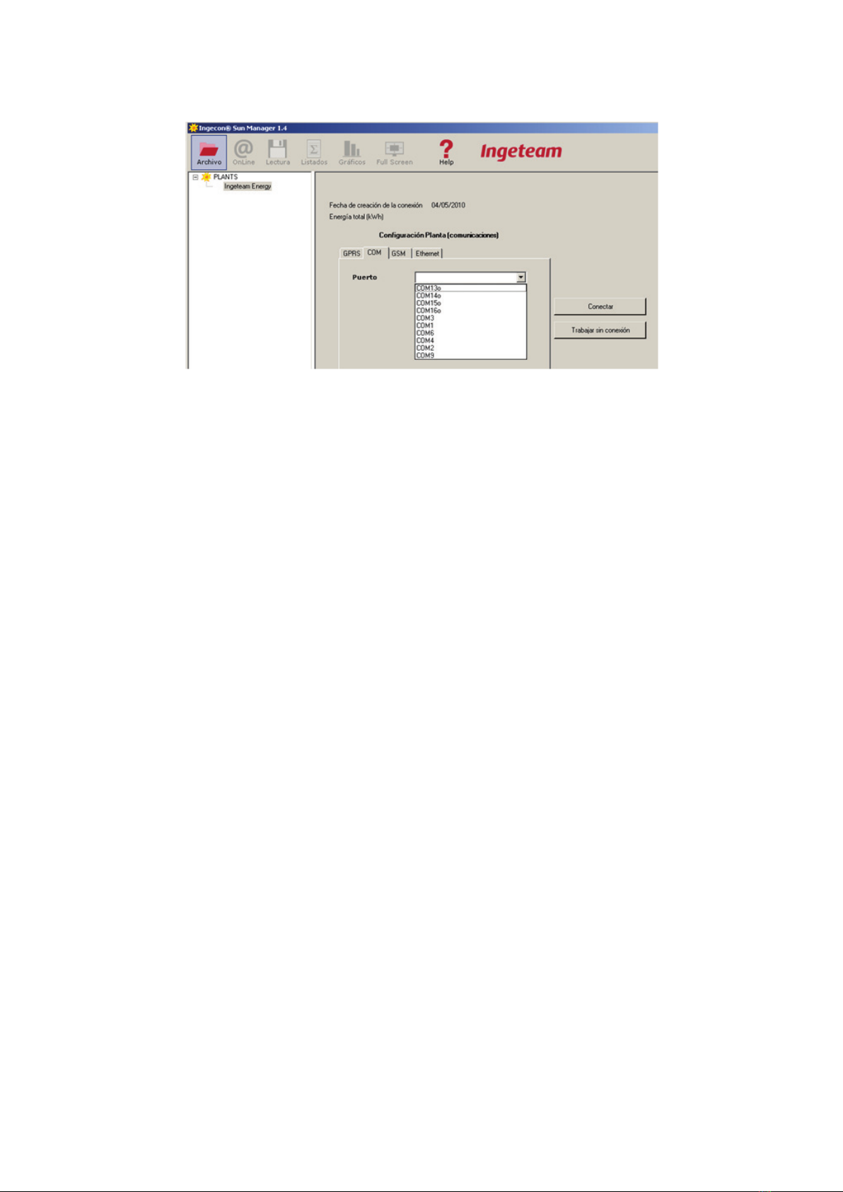
2. The monitor program is configured in Opciones -> Configuración comunicaciones (options - communications
configuration) by selecting the port number corresponding to the converter.
AAX2002IKI01
10
Installation ManualIngeteam Energy, S.A.
AAP0058 - RS-485 to RS-232 Converter
Reference AAP0058 corresponds to the supply of an RS-232 to RS-485 converter for connection to a PC serial port.
Settings
Set the converter switches as follows:
• Left to “T-RTS, R-/RTS” (central position)
• Right to DCE (top position)
Connections
1. Connect the converter to the PC.
2. Configure it for half duplex communication by connecting converter pins 1(T+) and 4(R+) to communications
board pin 1 and terminals 2(T-) and 3(R-) to pin 2.
3. Power-up the converter.
AAX7030 - Kit RS-485-USB for Ingecon®Sun
Reference AAX7030 corresponds to the supply of a USB to RS-485 converter and the appropriate connectors, for
either three phase inverters or the Ingecon®Sun Lite units.
For the three phase inverters, the pin settings are as described in the table above.
For the Ingecon®Sun Lite, discard the cable with a push-pull connector to PCB on one end and a Harting connector
on the other. The pin settings are as described in the table on the next page.
The driver required for the kit is available at: www.ftdichip.com/Drivers/VCP.htm.
Installing the driver
1. Download the driver from www.ftdichip.com/Drivers/VCP.htm.
2. Connect the converter to the computer USB port. The installation will start automatically, although you will
have to select the location where you saved the driver.
3. The installation will prompt for the drivers again, and the same source should be indicated.
4. Once completed, open the device manager (Administrador de dispositivos) from either the control panel or
from the Start Menu -> Execute (Menú de Inicio -> Ejecutar)... and type in devmgmt.msc.

AAX2002IKI01 11
Ingeteam Energy, S.A.Installation Manual
5. On port element Puertos (COM & LPT) you will see the new COMx port that the system has associated with
the converter, called USB Serial Port or FTDI USB Serial Port (depending on the driver version). Its port number
will be used in the configuration of the Ingecon®Sun Manager.
Ingecon®Sun ComBox
The Ingecon®Sun ComBox can be used as shown in the following figure:
E
E E
E E E
B B B B B B
A
D
C
A. Ingecon®Sun ComBox.
B. Ingecon®Sun units connected to the bus
C. Local PC
D. USB or RS-485, or Ethernet Cable
E. RS-485 cabling
Refer to section “5. Ingecon®Sun ComBox” for further information on the Ingecon®Sun ComBox Centralised commu-
nication hardware.

AAX2002IKI01
12
Installation ManualIngeteam Energy, S.A.
3.2. Local Ethernet communication
All the Ingecon®Sun Ethernet communication accessories incorporate Ethernet to serial port conversion hardware and
have a similar operation, set by default.
They have a fixed IP address assigned and are programmed as TCP servers to accept a connection from the
Ingecon®Sun Manager client software. The default port number through which connections are received is 7218.
Only one client at a time is accepted.
For local communication, the following is required:
• The serial Ethernet converter in equipment A and local computers D must be in the same sub-network.
• The number of the TCP port in which the converter accepts connections.
• There are not two or more devices with the same IP address.
E E E E E
FF
G
F
F
C
DD
A
B
B B B
B
A. Ingecon®Sun with AAX7004 (Ethernet and RS-485 communications card), or Ingecon®Sun Lite with
AAX0023 (Ethernet and RS-485 communications card), or Ingecon®Sun Smart 15 UL with kit AAS0173, or
Ingecon®Sun Smart 25 UL with kit AAS0173, or Ingecon®Sun Power 100 UL with kit AAS0174.
B. Ingecon®Sun units connected to the same bus as A.
C. Ingecon®Sun units with AAP0067 (Ethernet communications card).
D. Local PCs.
E. RS-485 cabling.
F. Ethernet cabling.
G. Network switch.

AAX2002IKI01 13
Ingeteam Energy, S.A.Installation Manual
3.2.1. Ingecon®Sun Ethernet accessories
AAX7023
Reference AAX0023 corresponds to the supply of board AAX7004, communications cable RS-485 AQL0089, flat
cable AQL0090, and the PG cable gland required to guarantee the leak tightness of the equipment at the Ethernet
cable inlet connection.
AAX7004
Communications board AAX7004 / AAX0023 RS-485 interface permits Ethernet communication with a number
of Ingecon®Sun units connected in a bus configuration. It is factory set with IP address IP 192.168.127.253. This
accessory does not incorporate the alarm or report sending functions.
Pin Signal
1 RS-485 B (+)
2 RS-485 A (-)
4GND
Settings
Should you wish to change this address, once connected to the equipment sub-network ( by default 192.168.127.0/24),
you need to open the Internet browser and type in http://192.168.127.253. A Log-in prompt will appear in which
neither the user name or password need to be entered. This takes you to the following page:
The IP address can be changed in the “Network” section. Once a change has been made, remember to click on “Apply
Settings”. Remember that all the equipment must be in the same sub-network.

AAX2002IKI01
14
Installation ManualIngeteam Energy, S.A.
Restoring the IP
The AAX004 board incorporates the Ethernet series TTL XPORT-03 manufactured by Lantronix. If you do not know
the IP address configured in the converter, you can use the “Device Installer” software provided by Lantronix to make
a MAC level search.
The ‘deviceinstaller’ search on the Lantronix web returns links to the software download page. Install and proceed as
shown in the following photos.
Clicking on ‘Search’ shows the items of equipment and their IP addresses.
AAP0067
Board AAP0067 offers Ethernet to serial conversion for a single Ingecon®Sun unit. It is factory set with IP address
192.168.127.254.
Settings
Should you wish to change this address, once connected to the equipment sub-network, you need to open your
Internet browser and enter http://192.168.127.254. This takes you to the following page:

AAX2002IKI01 15
Ingeteam Energy, S.A.Installation Manual
To change the IP address, access the Network Settings folder and click on the “Submit” button to apply the changes.
IP restoration
Board AAP0067 incorporates the Ethernet - serial converterTTL NE-4100T manufactured by MOXA. If you do not
know the IP address configured for the converter, you can use the “NPort Search Utility” software supplied by Moxa
to make a MAC level search.
The ‘NPort Search Utility 4100’ on the Moxa website returns the link to the installation file. Install and proceed as
shown in the following images:
Click on ‘Search’:

AAX2002IKI01
16
Installation ManualIngeteam Energy, S.A.
A dialogue will be displayed and there will be an approximate 10 second search for devices:
And will finally present the results.
AAS0173
The 25-15 kW UL units can optionally be supplied with kit AAS0173 for Ethernet communication. It incorporates an
Ethernet - RS-485 converter to be used like the AAX7004, providing Ethernet connectivity to all the units connected
in a bus configuration.
AAS0174
The 100 kW UL can optionally be supplied with kit AAS0174 for Ethernet communication. It incorporates an Ethernet
- RS-485 converter to be used like the AAX7004, providing Ethernet connectivity to all the units connected in a bus
configuration.
3.2.2. Ethernet communication with the Ingecon®Sun units
Ingecon®Sun Lite
In order to install an Ethernet communication card in the Ingecon®Sun Lite units, you first need to disable the
RS-485 communication, installed as standard. To do so, proceed as described in “How to disable the factory set
RS-485 communication”. You can then install the accessory.

AAX2002IKI01 17
Ingeteam Energy, S.A.Installation Manual
How to disable the factory set RS-485 communication
The following photo, taken with the inverter control card removed, shows the location of lead AQL0053 which must
be replaced in order to disable the RS-485 communication through connector J19 on the power board.
This must be replaced by cable AQL0090 supplied with the Ingecon®Sun Lite communication accessories.
Installation
Remove the blank shown in the photo from the Ingecon®Sun Lite housing and fit a 20 diameter PG cable gland
through which the Ethernet Cabling will pass.
Pre-cut

AAX2002IKI01
18
Installation ManualIngeteam Energy, S.A.
Ingecon®Sun Smart, Power and Power Max
Communications board AAP0067/AAX7004 must be mounted on the control board specific communications
connector.
J11
J12
Read section “8. List of accessories” and always refer to the installation manual for the Ingecon®Sun inverter in
which a communications accessory is to be installed.
The cabling shall be made directly to the flying lead connector on board AAX7002. There is no defined position on the
equipment housing for bring out the cabling, however there are a number of ports available to do so.
Ingecon®Sun Power UL and Power Max UL
For these units, Ethernet communication is available, to order, through an off-the-shelf Ethernet to serial converter
which is factory set with the IP address IP 192.168.127.254 and, like the rest of the Ethernet communication acces-
sories, it receives TCP connections at port 7128.
Ingecon®Sun String Control
Communications board AAP0067 or AAX7004 must be mounted on the specific communications connector on the
String Control electronics board, and the cabling shall be made to the board push-pull connector. The RS-485 cabling
shall be taken out through the PG cable gland designed for this purpose.
Models prior to 2009
Use the earlier version of this document, AAX2002IKI01_.
This manual suits for next models
11
Table of contents
Popular Control Unit manuals by other brands

SMC Networks
SMC Networks IL201 Series Operation manual

Siemens
Siemens SINUMERIK 828D Turning Service manual

Eaton
Eaton Crouse-hinds series instruction sheet

ASAHI YUKIZAI
ASAHI YUKIZAI Dymatrix AVSDV user manual

Rockwell Automation
Rockwell Automation Allen-Bradley 1794-OB8EPXT installation instructions

Rain Bird
Rain Bird EASY RAIN manual

Bray
Bray TRI LOK Installation, operation & maintenance manual

Exhausto
Exhausto EBC 10-P Installation & operating manual

Radio Shack
Radio Shack Color Graphics Option installation instructions

Zator
Zator MZL100 User and maintenance manual

Emerson
Emerson CL600 instruction manual

Pando
Pando PI3300 Instructions for use


