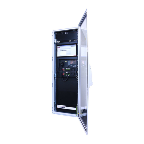
Hubbell GAI-Tronics Elemec3 MIM User manual

Pub. 502-20-0672-001 ISS4
G A I - T R O N I C S ®
A H U B B E L L C O M P A N Y
Elemec3
MIM (Monitored Input Module) and
MRM (Monitored Relay Module)
TA B L E O F CO N T E N T S
GAI-TRONICS 3030 KUTZTOWN RD. READING, PA 19605 USA
610-777-1374 ◼800-492-1212 ◼Fax: 610-796-5954
VISIT WWW.GAI-TRONICS.COM FOR PRODUCT LITERATURE AND MANUALS
Confidentiality Notice.....................................................................................................................1
Models..............................................................................................................................................1
Definitions.......................................................................................................................................1
Abbreviations...................................................................................................................................2
MIM (Monitored Input Module) Assemblies.................................................................................2
Application...............................................................................................................................................2
Data Interfaces........................................................................................................................................3
Inputs .......................................................................................................................................................3
Dry/Wet Input Selection .......................................................................................................................4
24 V/0 V Input Selection ......................................................................................................................4
Input Configuration...............................................................................................................................7
Monitored Relay Module (MRM) Assemblies..............................................................................10
Application.............................................................................................................................................10
Data Interfaces......................................................................................................................................10
CAN Bus.............................................................................................................................................10
Ethernet...............................................................................................................................................11
Inputs .....................................................................................................................................................13
Outputs (Relay Contacts).....................................................................................................................14
Unsupervised Relay Output Wiring....................................................................................................14
Supervised Relay Output Wiring........................................................................................................15
Block Diagrams.....................................................................................................................................17
Installation ....................................................................................................................................20
Installation Safety Guidelines..............................................................................................................20
Installation Guidelines..........................................................................................................................20
Mounting................................................................................................................................................20
Data Communication Connection.......................................................................................................21

CAN BUS MIM/MRM Modules—Power and Settings.....................................................................21
Power—System...................................................................................................................................21
Power—Local (Optional)....................................................................................................................21

Table of contents Pub. 502-20-0672-001 ISS 4
GAI-TRONICS 3030 KUTZTOWN RD. READING, PA 19605 USA
610-777-1374 ◼800-492-1212 ◼Fax: 610-796-5954
VISIT WWW.GAI-TRONICS.COM FOR PRODUCT LITERATURE AND MANUALS
Ground ................................................................................................................................................ 21
CAN Bus Address Setting...................................................................................................................22
CPU PCBA Jumper Settings............................................................................................................... 22
Ethernet MIM/MRM Modules—Power and Settings .......................................................................23
Power ..................................................................................................................................................23
Ground ................................................................................................................................................ 23
Ethernet MIM/MRM Module Settings ...............................................................................................23
CPU PCBA Jumper Settings............................................................................................................... 23
Using PuTTY for Ethernet MIM/MRM Administration ....................................................................24
Serial Port Connection........................................................................................................................24
The Command Line Interface (CLI)...................................................................................................27
Operation.......................................................................................................................................30
Fault Diagnostics..........................................................................................................................30
Reference Documentation ............................................................................................................32
Specifications ................................................................................................................................32
Electrical................................................................................................................................................32
Mechanical.............................................................................................................................................33
Environmental.......................................................................................................................................33
Glossary of Terms .........................................................................................................................34
Revision History............................................................................................................................35

Pub. 502-20-0672-001 ISS4
G A I - T R O N I C S ®
A H U B B E L L C O M P A N Y
Elemec3
MIM (Monitored Input Module) and
MRM (Monitored Relay Module)
GAI-TRONICS 3030 KUTZTOWN RD. READING, PA 19605 USA
610-777-1374 ◼800-492-1212 ◼Fax: 610-796-5954
VISIT WWW.GAI-TRONICS.COM FOR PRODUCT LITERATURE AND MANUALS
Confidentiality Notice
This installation, operation, and maintenance manual contains sensitive business and technical
information that is confidential and proprietary to GAI-Tronics. GAI-Tronics retains all intellectual
property and other rights in or to the information contained herein, and such information may only be
used in connection with the operation of your GAI-Tronics product or system. This manual may not be
disclosed in any form, in whole or in part, directly or indirectly, to any third party.
Models
Elemec3 MIM (Monitored Input Module) models:
•030-02-0096-001 CAN BUS MIM
•030-02-0098-001 Ethernet MIM
Elemec3 MRM (Monitored Relay Module) models:
•030-02-0097-004 CAN BUS MRM 4 Circuits Standard Relay Mount
•030-02-0097-014 CAN BUS MRM 4 Circuits Alternate Relay Mount
•030-02-0097-008 CAN BUS MRM 8 Circuits Standard Relay Mount
•030-02-0097-018 CAN BUS MRM 8 Circuits Alternate Relay Mount
•030-02-0099-004 Ethernet MRM 4 Circuits Standard Relay Mount
•030-02-0099-014 Ethernet MRM 4 Circuits Alternate Relay Mount
•030-02-0099-008 Ethernet MRM 8 Circuits Standard Relay Mount
•030-02-0099-018 Ethernet MRM 8 Circuits Alternate Relay Mount
Definitions
High Voltage—An electrical potential greater than 42.4 V peak or 60 V dc
Low Voltage—An electrical potential less than or equal to 42.4 V peak or 60 V dc

Pub. 502-20-0672-001 ISS4
Elemec3 MIM (Monitored Input Module) and MRM (Monitored Relay Module) Page 2 of 35
Change Note: 37431-146
Abbreviations
CPU—central processing unit PCBA—printed circuit board assembly
EOL—end of line LOC—local
MIM (Monitored Input Module) Assemblies
Application
The Model 030-02-0096-001 and 030-02-0098-001 Elemec3 MIMs provide inputs to Elemec3 PAGA
(public address and general alarm) systems. MIM’s receive up to eight inputs from field devices, monitor
the integrity of the input cabling for trouble conditions or activation, and report these conditions to the
Elemec3 controller.
MIMs have two components: a CPU PCBA and a Monitored-In-8 PCBA. The CPU on the Model 030-
02-0096-001 MIM uses a CAN bus communication protocol; the Model 030-02-0098-001 MIM uses an
Ethernet based communication protocol. Both assemblies mount on 4-inch snap track (see Figure 1 and
Figure 2).
Figure 1. Model 030-02-0096-001 and 030-02-0098-001 Monitored Input Modules

Pub. 502-20-0672-001 ISS4
Elemec3 MIM (Monitored Input Module) and MRM (Monitored Relay Module) Page 3 of 35
Change Note: 37431-146
Figure 2. Models 030-02-0096-001 and 030-02-0098-001 Monitored Input Modules—Mounting
Configuration
Data Interfaces
Data communication between the MIM and the Elemec3 controller takes place over a CAN bus interface
or an Ethernet interface (see Figure 1 showing each MIM type with corresponding CPU card).
The Model 030-02-0096-001 Elemec3 MIM interfaces to the Elemec3 controller via the I/O port (CAN
bus). The Elemec3 controller monitors the MIM devices (via the CAN bus cable). Assign each MIM a
unique address by setting the hexadecimal switch on the MIM's CPU card (see the CAN Bus Address
Setting section). The MIM reports input circuit activations and input cable fault conditions to the
controller. Elemec3 controllers sense interruptions in data communication between each MIM and the
controller as a device fault condition.
The Model 030-02-0098-001 Elemec3 MIM interfaces to the Elemec3 controller cabinet via an Ethernet
connection. The Elemec3 controller monitors the MIM devices via Ethernet connection. Assign each
MIM its device address and network parameters (see the Ethernet MIM/MRM Module Settings section).
The MIM reports input circuit activations and input cable fault conditions to the controller. Elemec3
controllers sense interruptions in data communication between each MIM and the controller as a device
fault condition.
Inputs
The MIM contains eight individually configurable inputs to interface with field devices. Configure each
input via a series of jumper settings on the PCBAs and specifically selected configuration modes in the
Elemec3 Console configuration utility.
The input circuit type determines which connection (A or B) to use for each input circuit. Use an input’s
A connection ONLY for supervision of high voltage devices (i.e. supervised beacons) or outdoor field
wiring. Use an input’s B connection for all other input applications. Use jumpers P27 (IN1) through
P34 (IN8) to set the connection of each input to A or B (see Figure 3, Table 1, and Table 2). Setting an
input to connection B, requires additional jumper settings to set the contact input to wet or dry and
configure the active condition for wet contacts to either 0-volts or 24-volts (see Figure 4, Table 3, Table
4, and Table 5).

Pub. 502-20-0672-001 ISS4
Elemec3 MIM (Monitored Input Module) and MRM (Monitored Relay Module) Page 4 of 35
Change Note: 37431-146
Set the jumper to position A and connect the input to one of the connection A terminals (TB1 thru TB8)
for supervision of high voltage devices. Set the jumper to the B position and connect the input to one of
the B terminals (TB14 to TB21) for all other input applications.
WARNING —Failure to comply with these instructions could result in death or serious
injury.
1. Terminals TB1 to TB8 (A connections) are galvanically isolated inputs ONLY used for outdoor
wiring or the supervision of high voltage devices (i.e. supervised beacons). DO NOT connect any
other inputs to these terminals. Failure to comply with these instructions could result in death or
serious injury.
2. Terminals TB14 to TB21 (B connections) are non-isolated inputs for indoor wiring low voltage
inputs ONLY. DO NOT connect supervised high voltage inputs to these terminals. Failure to
comply with these instructions could result in death or serious injury.
Figure 3. Jumper Locations on the Monitored-In-8 PCBA
Dry/Wet Input Selection
Each connection B input contains two jumpers to select between dry (voltage-free)or wet (24 V dc)
inputs. For dry inputs, place both jumpers in the DRY position. For wet inputs, place both jumpers in the
WET position. When in the wet mode, the 24 V/0 V jumper must also be set (see Table 3, Table 4, and
Table 5 for input jumper configuration details).
24 V/0 V Input Selection
Each connection B input contains a jumper to select between 24 V and 0 V when using wet inputs. The
input activates with the application (24V setting) or removal (0V SETTING) of 24 V to the input (see
Table 4 and Table 5 for input jumper configurations).
NOTES:
• Inputs are polarity sensitive. Ensure the polarity of each input connection is correct.
• Fault monitoring does not occur for circuits configured for wet mode.

Pub. 502-20-0672-001 ISS4
Elemec3 MIM (Monitored Input Module) and MRM (Monitored Relay Module) Page 5 of 35
Change Note: 37431-146
Table 1. (High Voltage) Connection A Input Supervision Configuration
Input
Input Terminal
Input Type Jumper
Factory Default Setting
1
TB1 (IN1A)
P27—A
YES
2
TB2 (IN2A)
P28—A
YES
3
TB3 (IN3A)
P29—A
YES
4
TB4 (IN4A)
P30—A
YES
5
TB5 (IN5A)
P31—A
YES
6
TB6 (IN6A)
P32—A
YES
7
TB7 (IN7A)
P33—A
YES
8
TB8 (IN8A)
P34—A
YES
Table 2. (Low Voltage) Connection B Input Configuration
Input
Input Terminal
Input Type Jumper
Factory Default Setting
1
TB14 (IN1B)
P27—B
NO
2
TB15 (IN2B)
P28—B
NO
3
TB16 (IN3B)
P29—B
NO
4
TB17 (IN4B)
P30—B
NO
5
TB18 (IN5B)
P31—B
NO
6
TB19(IN6B)
P32—B
NO
7
TB20 (IN7B)
P33—B
NO
8
TB21 (IN8B)
P34—B
NO
Table 3. (Low Voltage) Connection B Dry Contact Input Configuration
Input
Input Type Jumper
Factory Default Setting
24V/0V Jumper
1
P1—DRY
P2—DRY
YES
P3—N/A
2
P4—DRY
P5—DRY
YES
P6—N/A
3
P7—DRY
P8—DRY
YES
P9—N/A
4
P10—DRY
P11—DRY
YES
P12—N/A
5
P13—DRY
P14—DRY
YES
P15—N/A
6
P16—DRY
P17—DRY
YES
P18—N/A
7
P19—DRY
P20—DRY
YES
P21—N/A
8
P22—DRY
P23—DRY
YES
P24—N/A

Pub. 502-20-0672-001 ISS4
Elemec3 MIM (Monitored Input Module) and MRM (Monitored Relay Module) Page 6 of 35
Change Note: 37431-146
Table 4. (Low Voltage) Connection B Wet Contact Input Configuration (Active State for 24 V)
Input
Input Type Jumper
Factory Default Setting
24V/0V Jumper
1
P1—WET
P2—WET
NO
P3—24V
2
P4—WET
P5—WET
NO
P6—24V
3
P7—WET
P8—WET
NO
P9—24V
4
P10—WET
P11—WET
NO
P12—24V
5
P13—WET
P14—WET
NO
P15—24V
6
P16—WET
P17—WET
NO
P18—24V
7
P19—WET
P20—WET
NO
P21—24V
8
P22—WET
P23—WET
NO
P24—24V
Table 5. (Low Voltage) Connection B Wet Contact Input Configuration (Active State for 0 V)
Input
Input Type Jumper
Factory Default Setting
24V/0V Jumper
1
P1—WET
P2—WET
NO
P3—0V
2
P4—WET
P5—WET
NO
P6—0V
3
P7—WET
P8—WET
NO
P9—0V
4
P10—WET
P11—WET
NO
P12—0V
5
P13—WET
P14—WET
NO
P15—0V
6
P16—WET
P17—WET
NO
P18—0V
7
P19—WET
P20—WET
NO
P21—0V
8
P22—WET
P23—WET
NO
P24—0V

Pub. 502-20-0672-001 ISS4
Elemec3 MIM (Monitored Input Module) and MRM (Monitored Relay Module) Page 7 of 35
Change Note: 37431-146
Input Configuration
Use the Elemec3 Console application to configure each input to operate in one of five input modes.
Determine the mode to select by the type and quantity of switch contacts in each circuit and the circuit’s
line supervision requirement. Install end of line resistors for circuits with line supervision enabled (see
Figure 4–Figure 8 for wiring diagrams).
• Disabled—Deactivates the circuit.
• N.O. Multi (Supervised)—Multiple normally open switches with line supervision enabled.
• N.O. (Supervised)—Single normally open switch with line supervision enabled.
• N.C. (Supervised)—Single normally closed switch with line supervision enabled.
• N.O. Multi (Unsupervised)—Single or multiple normally open switches with line supervision
disabled.
Each mode requires a unique connection scheme between the external field device(s) and the appropriate
input terminal block on the MIM. The following subsections provide the connection scheme for each
mode.
Disabled:
Use this mode to disable the monitoring of a selected input circuit. The MIM does not monitor the input
in this mode.
NOTE: It is good practice to set all spare inputs (without field wiring connections) to this mode.
N.O. Multi (Supervised):
Use this mode for circuits with any number of NO contacts (see Figure 4) and monitor the circuit for:
• ground faults • open circuits
1. Install any number of NO (normally open) dry contacts in parallel in the circuit.
2. Install a 20-kilohm, 5% tolerance resistor across the end-of-line device terminals (see note below).
The circuit resistance is 20 kilohms when all contacts are inactive (open). The MIM detects this
resistance across the contacts, indicating a healthy circuit.
Figure 4. Multiple Normally Open Switches (with line supervision)
When any contact activates (closes), it bypasses the 20-kilohm resistor (REOL). The input detects the
circuit resistance without the terminating resistor, indicating a contact closure (active). The MIM signals
ground faults and opens on either leg to the E3 controller.

Pub. 502-20-0672-001 ISS4
Elemec3 MIM (Monitored Input Module) and MRM (Monitored Relay Module) Page 8 of 35
Change Note: 37431-146
NOTE: The Model 030-02-0096-001 and Model 030-02-0098-001 MIMs do not include the 20-kilohm,
5% tolerance resistor. Kit 12509-003 (purchased separately) includes this resistor.
N.O. (Supervised):
Use this mode for circuits with a single NO dry contact (see Figure 5) to monitor for:
• open circuits • wire-to-wire short circuits (across + and −) • ground faults
1. Install only one NO contact in the circuit.
2. Install the terminating resistors in series and parallel with the device terminals (see Figure 5) (see note
below).
The circuit resistance is 20.1 kilohms (15 kilohms in series with 5.1 kilohms) when the contact is not
active (open). The MIM detects this resistance, indicating a healthy circuit.
Figure 5. Single Normally Open Switch (with line supervision)
When the contact activates (closes), it bypasses the 15-kilohm resistor. The input detects the 5.1-kilohm
load, indicating the contact closed (active). The MIM reports a fault condition to the E3 controller if there
is a wire-to-wire short (across + and −), a ground fault on either leg, or an open on either leg.
NOTE: The 030-02-0096-001 and 030-02-0098-001 MIM’s do not include the terminating resistors. Kit
12509-003 (purchased separately) includes the resistors.
N.C. (Supervised):
Use this mode for circuits with a single NC dry contact (see Figure 6) to monitor the circuit for:
• open circuits • wire-to-wire short circuits (across + and −) • ground faults
1. Install only one NC contact in the circuit.
2. Install the terminating resistors in series and parallel with the device terminals (see Figure 6).
When the contact is inactive (closed), it bypasses the 15-kilohm resistor, and the circuit sees only the 5.1-
kilohm load. The MIM detects this resistance, indicating a healthy circuit.

Pub. 502-20-0672-001 ISS4
Elemec3 MIM (Monitored Input Module) and MRM (Monitored Relay Module) Page 9 of 35
Change Note: 37431-146
Figure 6. Single Normally Closed Switch (with line supervision)
The circuit resistance is 20.1 kilohms when the contact activates (opens) (15 kilohms in series with 5.1
kilohms). The change in input resistance indicates the contact is open (active). The MIM reports a fault
condition to the E3 controller if there is a wire-to-wire short (across + and −), a ground fault on either leg,
or an open on either leg.
NOTE: The 030-02-0096-001 and 030-02-0098-001 do not include the terminating resistors. Kit 12509-
003 (purchased separately) includes the resistors.
N.O. Multi (Unsupervised):
Use this mode for circuits with any number of NO dry contacts installed (see Figure 7). No circuit
monitoring for fault conditions occurs in this mode.
Figure 7. Multiple Normally Open Switches (without line supervision)
24V DC Wet Inputs
Use the Elemec3 Console application to set the input circuit to N.O Multi (Unsupervised) when
connecting wet inputs to the MIM. Wire the input circuit as shown below (see Figure 8). No circuit
monitoring for fault conditions occurs in this mode.
1. Move the shorting jumpers for the input from the factory default dry to wet contact mode (see Figure
3 and Table 2).
2. The input activates during a 0-volt condition or a 24-volt condition in wet contact mode.
The factory default setting is 24 V dc input when active (position 2-3).
3. Move the jumper from position 2-3 to position 1-2 for 0 V dc input active operation.
The input connection is polarity sensitive.

Pub. 502-20-0672-001 ISS4
Elemec3 MIM (Monitored Input Module) and MRM (Monitored Relay Module) Page 10 of 35
Change Note: 37431-146
Figure 8. 24V DC Wet Input (without line supervision).
Monitored Relay Module (MRM) Assemblies
Application
Models 030-02-009X-0X4 (four output) and 030-02-009X-0X8 (eight output) MRM (Monitored Relay
Modules) are for use in Elemec3 PAGA (Public Address and General Alarm) systems. MRM modules
provide either four or eight relay-contact outputs. Typical applications include switching power to
signaling devices (i.e. beacons) or providing contact closure signaling to external systems/devices. The
Elemec3 controller controls each relay individually based on system configuration settings and system
conditions.
The MRMs contain eight input circuits as described in the MIM (Monitored Input Module) section of this
manual. In addition to the MIM input functions mentioned above, the MRM inputs can supervise the
field wiring connected to the relay outputs. A typical application is monitoring the power cable
connecting beacons to the MRM output relays. A MRM input monitors the field wiring for open-circuit,
wire-to-wire short circuit, and ground fault conditions. An end-of-line resistor is required at the last
device on the field cable run.
The MRM assemblies have alternate relay mounting arraignments so that the relay terminal blocks face
either the connection A input terminal side or the connection B input terminal side of the circuit board.
Refer to figures Figure 10 and Figure 11 (Models 030-02-009X-00X) and Figure 12 and Figure 13
(Models 030-02-009X-01X).
Data Interfaces
The MRM connects to the Elemec3 controller via CAN bus or Ethernet network for data communication
(see Figure 9).
CAN Bus
The Model 030-02-0097-0X1 Elemec3 MRMs interface to the Elemec3 controller via the I/O port CAN
bus.
The Elemec3 controller monitors the MRM inputs and controls the MRM relays via the CAN bus cable.
Assign each MRM a unique address using the hexadecimal switch on the MRM’s CPU card (see the CAN
Bus Address Setting section). The Elemec3 controller reports a device fault condition for any interruption
in data communication between the Elemec3 controller and the MRM.

Pub. 502-20-0672-001 ISS4
Elemec3 MIM (Monitored Input Module) and MRM (Monitored Relay Module) Page 11 of 35
Change Note: 37431-146
Ethernet
The Model 030-02-0099-0X1 Elemec3 MRMs interface to the Elemec3 controller via an Ethernet local
area network connection.
The Elemec3 controller monitors the MRM inputs and controls the MRM relays via Ethernet connection.
Assign each MRM its device address and network parameters (see the Ethernet MIM/MRM Module
Settings section). The Elemec3 controller reports a device fault condition for any interruption in data
communication between the Elemec3 controller and a MRM.
Figure 9. Models 030-02-0097-0XX and 030-02-0099-0XX Monitored Relay Modules

Pub. 502-20-0672-001 ISS4
Elemec3 MIM (Monitored Input Module) and MRM (Monitored Relay Module) Page 12 of 35
Change Note: 37431-146
Figure 10. Models 030-02-0097-004 and 030-02-0099-004 Monitored Relay Modules
(Standard Mounting Configuration)
Figure 11. Models 030-02-0097-008 and 030-02-0099-008 Monitored Relay Modules
(Standard Mounting Configuration)

Pub. 502-20-0672-001 ISS4
Elemec3 MIM (Monitored Input Module) and MRM (Monitored Relay Module) Page 13 of 35
Change Note: 37431-146
Figure 12. Models 030-02-0097-014 and 030-02-0099-014 Monitored Relay Modules
(Alternate Mounting Configuration)
Figure 13. Models 030-02-0097-018 and 030-02-0099-018 Monitored Relay Modules
(Alternate Mounting Configuration)
Inputs
Inputs not used for relay output cable supervision are available to monitor dry or wet contact inputs as
described in the MIM section of this manual

Pub. 502-20-0672-001 ISS4
Elemec3 MIM (Monitored Input Module) and MRM (Monitored Relay Module) Page 14 of 35
Change Note: 37431-146
Outputs (Relay Contacts)
The MRM contains either four or eight individually configurable relay-contact outputs (depending on the
model) with status indicators; allowing it to control field devices such as beacons. Make the connections
for these field devices at terminal blocks TB1 through TB8 on the power relay modules.
There are two terminal blocks on each DPDT (Double Pole Double Throw) output contact on the power
relay module (i.e. TB1 and TB2 are for output #1, TB3 and TB4 are for output #2, etc.) Additional
details on the output contact terminals and status indicators is provided below (see Table 6).
To ensure proper wire termination, crimp ferrules on the ends of all conductors terminated at the terminal
blocks. The size of the ferrule is dependent upon the size of the conductor used. Source the ferrules from
any supplier such as Phoenix, Altech, or Weidmuller.
Table 6. Relay Contact Outputs
Output
Power Relay Module
Terminals
Relay Contact
Status LED
1
Lower
TB1
TB2
1
2
DS1
2
Lower
TB3
TB4
1
2
DS2
3
Lower
TB5
TB6
1
2
DS3
4
Lower
TB7
TB8
1
2
DS4
5
Upper
TB1
TB2
1
2
DS1
6
Upper
TB3
TB4
1
2
DS2
7
Upper
TB5
TB6
1
2
DS3
8
Upper
TB7
TB8
1
2
DS4
Unsupervised Relay Output Wiring
The Elemec3 system uses the relay contacts to switch power to one or more signaling devices (i.e.
flashing beacons) using the normally open and common relay contacts. This mode supports both ac-
powered (see Figure 14) and dc-powered (see Figure 15) signaling devices (both figures use OUT1
(Output 1) as an example). The system does not supervise the cable supplying power to the signaling
device.
*NOTE:The MRM does not contain any current limiting for the signaling device power. GAI-Tronics
recommends installing an external fuse or circuit breaker for each output circuit with the
appropriate voltage and current ratings. Fuses should be of the slow-blow variety.

Pub. 502-20-0672-001 ISS4
Elemec3 MIM (Monitored Input Module) and MRM (Monitored Relay Module) Page 15 of 35
Change Note: 37431-146
Figure 14. Unsupervised AC-Powered Beacons
Figure 15. Unsupervised DC-Powered Beacons
Supervised Relay Output Wiring
Supervise the field cables connected to relay-contact outputs 1–8 using the corresponding A input circuit
and install a 20-kilohm end-of-line resistor on the field cable. Relay output #1 wiring is shown below for
dc-powered signaling devices (see Figure 16) and for ac-powered signaling devices (see Figure 17).
Outputs 2–8 are identical to outputs 1–8 using the appropriate terminals on the MRM. Configure the
MRM input cicuits for RELAY SUPERVISION using the Elemec3 Console configuration utility.
*NOTE: The MRM does not contain any current limiting for the signaling device power. GAI-Tronics
recommends installing an external fuse or circuit breaker for each output circuit with the
appropriate voltage and current ratings. Fuses should be the slow-blow type.

Pub. 502-20-0672-001 ISS4
Elemec3 MIM (Monitored Input Module) and MRM (Monitored Relay Module) Page 16 of 35
Change Note: 37431-146
Figure 16. Supervised DC-Powered Beacons
Install one blocking diode for each dc signaling device connected to the power cable. The end-of-line
resistor (REOL) is a 20-kilohm, 2-watt, 5% tolerance resistor. Observe all polarities (see Figure 16).
NOTE: Some signaling devices already include a blocking diode in the unit. Do not install an additional
blocking diode in this case.
NOTE: The MRM does not include the blocking diodes, wire jumpers, or the 20-kilohm, 2-watt, 5%
tolerance resistor. Order these items separately.
Figure 17. Supervised High Voltage AC-Powered Beacons
NOTE: The MRM does not include the wire jumpers or the 20-kilohm, 10-watt, 5% tolerance resistor.
Order these items separately.

Pub. 502-20-0672-001 ISS4
Elemec3 MIM (Monitored Input Module) and MRM (Monitored Relay Module) Page 17 of 35
Change Note: 37431-146
Block Diagrams
J1
IN1A
C2
C1
TB2
MRM
K1
TB2
TB1
BEACON
AC
POWER
FUSE **
TB13
RLY CNTRL
TB1
+- TB1
+24V
RELAY
PCBA AC BEACON
20.0K
IN8
PCBA
NC2
NC1
CGND
CABINET
CHASSIS
GROUND
THICK LINES INDICATE FIELD WIRING.
NO2
NO1
WIRE JMPRS *
ELEMEC
CONTROLLER
CPU
PCBA
R *
SUPERVISION CKT
EOL
Figure 18. Elemec3 MRM Block Diagram—Typical Supervised High Voltage AC Beacon
*NOTE: The MRM does not include the wire jumpers, blocking diode, or end-of-line resistor (REOL).
Order these items separately.
**NOTE: The MRM does not provide current limiting capability for signaling device power. Install an
external slow-blow fuse for each output circuit with the appropriate voltage and current
ratings.
Figure 19. Elemec3 MRM Block Diagram—Typical Unsupervised High Voltage AC Beacon
**NOTE: The MRM does not provide current limiting capability for signaling device power. Install an
external slow-blow fuse for each output circuit with the appropriate voltage and current
ratings.

Pub. 502-20-0672-001 ISS4
Elemec3 MIM (Monitored Input Module) and MRM (Monitored Relay Module) Page 18 of 35
Change Note: 37431-146
Figure 20. Elemec3 MRM Block Diagram—Typical Supervised Low Voltage DC Beacon
*NOTE: The MRM does not include the wire jumpers, blocking diode, or end-of-line resistor (REOL).
Order these items separately.
**NOTE: The MRM does not provide current limiting capability for signaling device power. Install an
external slow-blow fuse for each output circuit with the appropriate voltage and current
ratings.
Figure 21. Elemec3 MRM Block Diagram—Typical Unsupervised Low Voltage DC Beacon
**NOTE: The MRM does not provide current-limiting capability for signaling device power. Install an
external slow-blow fuse for each output circuit with the appropriate voltage and current
ratings.
This manual suits for next models
1
Table of contents
Other Hubbell Control Unit manuals

Hubbell
Hubbell GAI-TRONICS HUBBCOM GRC600 User manual

Hubbell
Hubbell Gai-Tronics 12504-009 User manual

Hubbell
Hubbell H-MOSS CU300HD User manual

Hubbell
Hubbell GAI-TRONICS HUBBCOM GRC600 User manual

Hubbell
Hubbell GAI-TRONICS HUBBCOM GRC600SS User manual

Hubbell
Hubbell GAI-TRONICS 378-003 E3 IP MIM User manual

Hubbell
Hubbell GAI-TRONICS XCP0020A User manual

Hubbell
Hubbell GAI-TRONICS 379-003 IP MRM User manual

Hubbell
Hubbell wiHUBB User manual

Hubbell
Hubbell GAI-TRONICS E3 User manual