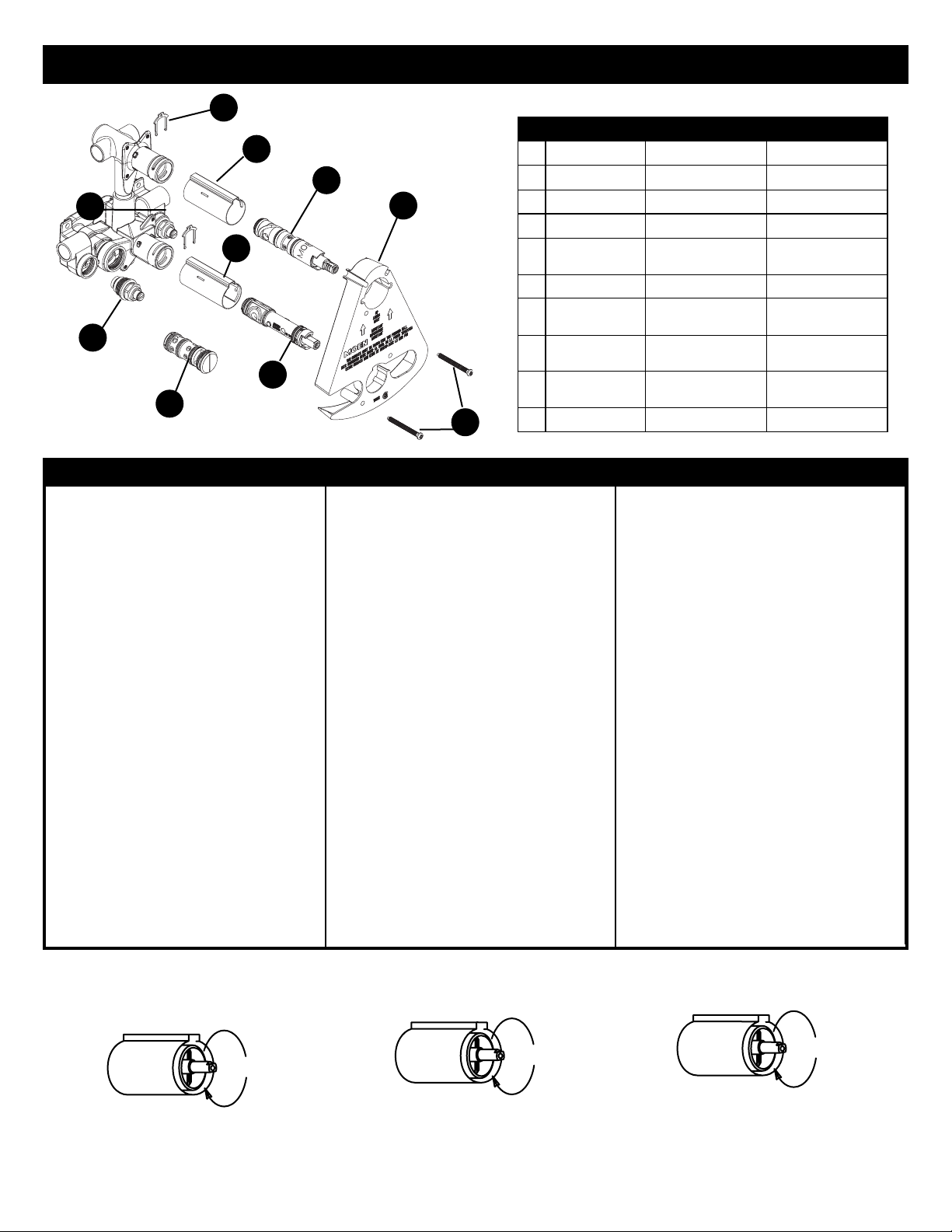
Moen MOENTROL 3320 User manual

FILE
LIMA
LIME
PLIERS
PINZAS
PINCES
DRILL
TALADRO
PERÇEUSE
TUBING CUTTER
CORTADOR DE TUBO
COUPE-TUYAU
FLASHLIGHT
LINTERNA
LAMPE DE POCHE
TILE SEALER
SELLADOR DE BALDOSA
MASTIC DE CÉRAMIQUE
ADJUSTABLE WRENCH
LLAVE AJUSTABLE
CLÉ ANGLAISE
HACKSAW
SIERRA DE ARMERO
SCIE À MÉTAUX
PHILLIPS SCREWDRIVER
DESTORNILLADOR DE ESTRELLA
TOURNEVIS À POINTE CRUCIFORME
PLUMBER'S PUTTY
MASILLA DE PLOMERO
MASTIC DE PLOMBIER
SAFETY GLASSES
GAFAS DE SEGURIDAD
LUNETTES DE SÉCURITÉ
HEX WRENCH
LLAVE HEXAGONAL
CLÉ HEXAGONALE
TORCH
SOLDADOR
CHALUMEAU
SOLDERING
SOLDERING
PASTE FLUX
PASTE FLUX
SOLDER KIT
EQUIPO DE SOLDAR
NÉCESSAIRE À SOUDER
FLATBLADED SCREWDRIVER
DESTORNILLADOR DE PALA
TOURNEVIS À TÊTE PLATE
For Safety and ease of faucet
replacement, Moen recommends the
use of these helpful tools.
Para la seguridad y facilidad de repuesto
de la mezcladora, Moen recomienda las
siguientes herramientas.
Par mesure de sécurité et pour faciliter
l’installation, Moen suggère l’utilisation
des outils suivants.
INS282A
®
HELPFUL TOOLS HERRAMIENTAS UTILES OUTILS UTILES
ENGLISH ESPAÑOL FRANÇAIS
MOENTROL®WITH BUILT IN THREE FUNCTION TRANSFER
VALVE INSTALLATION INSTRUCTIONS
MODELS 3320, 3330
MOENTROL®MUNI D’UN ROBINET COUPLEUR À TROIS
FONCTIONS - DIRECTIVES D’INSTALLATION
MODÈLES 3320, 3330
INSTRUCCIONES PARA LA INSTALACION DE LA VALVULA
MEZCLADORA MOENTROL®DE TRES FUNCIONES
MODELOS 3320, 3330
KEEP INSTRUCTIONS FOR
FUTURE REFERENCE
Thank you for purchasing a quality MOEN valve.
With simple care and maintenance, it will provide
you with many years of reliable performance.
Please read all instructions before installation.
TIPS FOR REMOVAL OF OLD FAUCET:
CAUTION: Always turn water OFF before
removing existing faucet or disassembling
the valve. Open faucet handle to relieve
water pressure and ensure that complete
water shut-off has been accomplished.
GUARDE ESTAS INSTRUCCIONES PARA
REFERENCIA FUTURA
Gracias por comprar una válvula MOEN de alta
calidad. Con un cuidado y mantenimiento
sencillos, le brindará muchos años de servicio
fiable. Por favor lea todas las instrucciones antes
de instalar.
SUGERENCIAS PARA RETIRAR LA VIEJA
MEZCLADORA:
ADVERTENCIA: Desconecte siempre el
agua antes de retirar la mezcladora
existente o desarmar la válvula. Abra los
manerales de la mezcladora para
desahogar la presión del agua y
asegurarse de que se ha logrado un corte
completo de la misma.
GARDER CES DIRECTIVES POUR
RÉFÉRENCE ULTÉRIEURE
Merci d’avoir acheté un soupape de qualité
MOEN. Avec un peu de soin et d’entretien, le
rendement fiable de ce produit durera plusieurs
années. Lire attentivement toutes les directives
avant de débuter l’installation.
SUGGESTIONS POUR ENLEVER L’ANCIEN
ROBINET :
ATTENTION :Toujours couper l’alimentation
en eau avant d’enlever ou de démonter le
soupape. Ouvrir la poignée du robinet pour
libérer la pression d’eau et pour s’assurer
que l’alimentation en eau a bien été coupée.
!!
©Moen Incorporated, 2002
Printed in U.S.A.
INS282A FEB ‘02
!
Complies with ASME A112.18.1M and CSA B125Complies with ASME A112.18.1M and CSA B125 Conformément à ASME A112.18.1M et CSA B125
En cumplimiento de ASME A112.18.1M y CSA B125

1INS282A
PARTS DIAGRAM DIAGRAMA DE PIEZAS TABLEAU DES PIÈCES
ENGLISH
ESPAÑOL
FRANÇAIS
1
Retainer Clip
Presilla Retenedora
Bride
2
Stop Tube
Tubo de Parada
Tube d'arrêt
3
Cartridge
Cartucho
Cartouche
4
Plaster Ground
Plantilla de Yeso
Arrêt d'enduit
5
Escutcheon
Screws
Tornillos de Chapetón
Vis de Rosace
6
Cartridge
Cartucho
Cartouche
7
Stop Tube
with Stop Nut
Tubo de Cierre con
Tuerca de Cierre
Tube d'arrêt avec
écrou de blocage
8
Balancing Spool
Carrete de
Compensación
Bobine d'équilibrage
9
Stop-Check Valve
Válvula Checadora-
de Cierre
Robinet à soupape
à clapet libre blocable
10
Retainer Clip
Presilla Retenedora
Bride
1
7
8
9
10
2
3
4
5
6
ENGLISH ESPAÑOL FRANÇAIS
IMPORTANT: Pipe chips, sand, stones and other
solids found in new and renovated plumbing can
damage the sealing surfaces of the cartridge and
cause leaks. To avoid damages, DO NOT
OPERATE VALVE until instructed below.
1. If the showerhead has been installed, remove it
before flushing.
2. Turn OFF hot and cold water at the integral
stops and open the handle to relieve pressure
and insure complete shut-off.
3. Remove adjustable temperature limit stop,
retainer clip and cartridge and balance spool
(unscrew balance spool with a wide-bladed
screwdriver and pull straight out of the valve).
4. At the integral stops, slowly turn both hot and
cold water on and thoroughly flush out the body
and lines.
5. Turn off both hot and cold water using the
integral stops.
6. Install balance spool, cartridge, retainer clip and
handle.
7. Turn the valve on in the mix position and open
both hot and cold stops.
8. Divert water to the shower and flush the riser.
9. Turn off the valve and install the showerhead.
10. Check the system for leaks.
FLUSHING INSTRUCTIONS
(after faucet installation) DIRECTIVES DE RINÇAGE
(après l’installation du robinet)
Para eliminar el entrecruce de cañerías en
instalaciones de ambos lados de la misma pared o
corregir instalaciones empotradas en la que las
posiciones Caliente y Frío están invertidas:
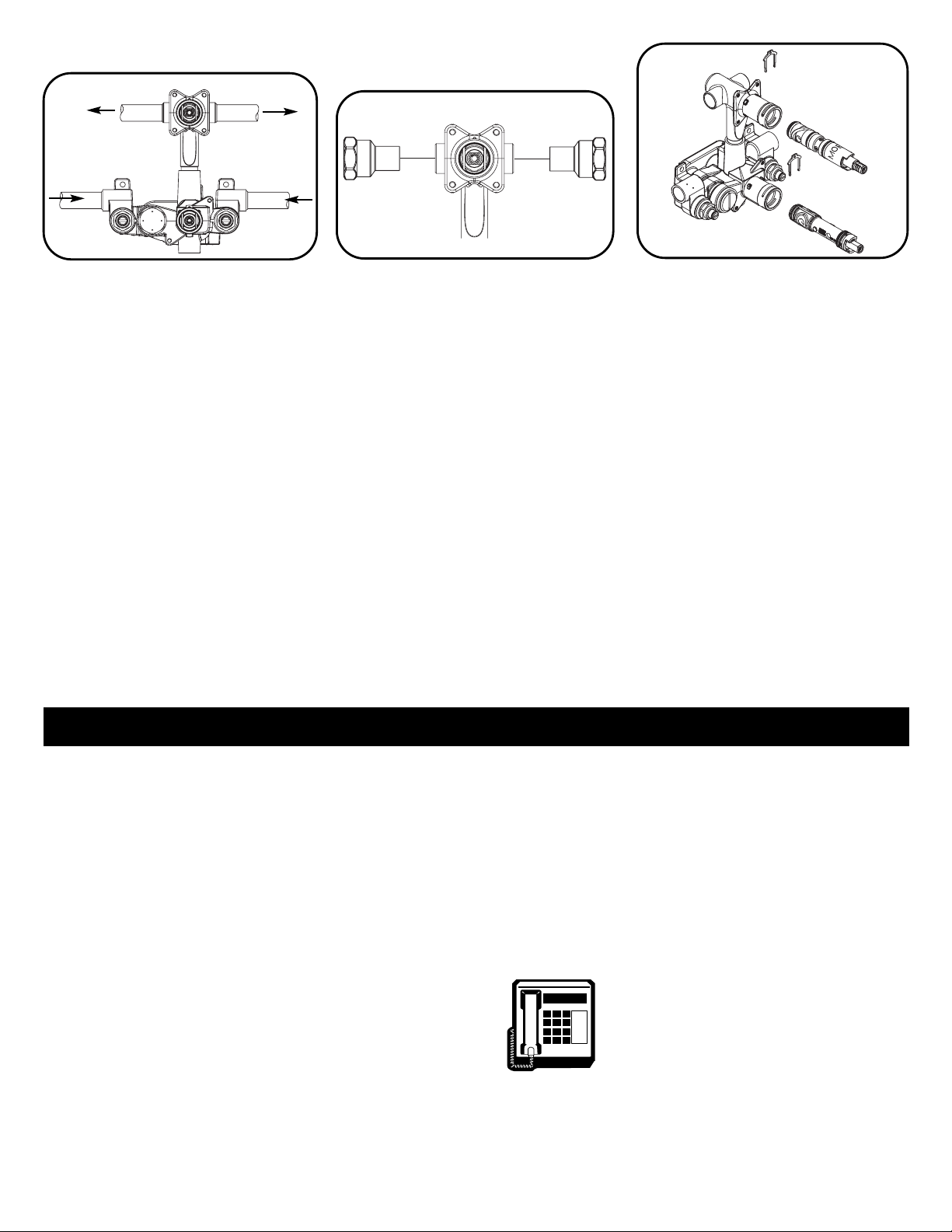
1. Remove handle parts.
2. Turn valve stem around so that the notched flat is
turned one half turn or 180 degrees.
3. Re-install handle parts. Tighten handle securely.
To eliminate Cross-Piping on Back-to-Back
Installations or to Correct Reversed Rough-In where
Hot and Cold Positions are Reversed:
1. Retire las piezas del maneral
2. Gire el vástago de la mezcladora de modo que la
muesca chata gire media vuelta o 180 grados
3. Re-instale las piezas del maneral y ajústelo
firmemente
IMPORTANT : Des débris de tuyauterie, du sable, de la
pierraille et d’autres solides, qui se trouvent dans toute
plomberie nouvelle et rénovée, peuvent endommager
les surfaces étanches de la cartouche et causer des
fuites. Pour prévenir de tels dommages, suivre les
directives ci-dessous AVANT D' OUVRIR LA SOUPAPE.
1. Si la pomme de douche est déjà installée, l’enlever
avant de rincer la plomberie.
2. FERMER l’eau chaude et l’eau froide aux robinets
d’arrêt intégrés et faire pivoter la poignée pour éliminer la
pression et s’assurer que l’alimentation en eau a bien
été coupée.
3. Enlever le limiteur de température réglable, la bride et
la cartouche ainsi que la bobine d’équilibrage. (Dévisser
la bobine d’équilibrage à l’aide d’un tourne-vis à grande
lame et tirer tout droit pour l’enlever de la soupape.).
4. Aux robinets d’arrêt intégrés, ouvrir l’eau chaude et
l’eau froide et bien rincer toute la plomberie.
5. Fermer l’eau chaude et l’eau froide à l'aide des
robinets d’arrêt intégrés.
6. Installer la bobine d’équilibrage, la cartouche, la bride
et la poignée.
7. Ouvrir la soupape à la position combinée et ouvrir les
robinets d’arrêt d’eau chaude et d’eau froide.
8. Inverser la direction de l’eau pour la faire passer par la
douche et rincer la colonne montante.
9. Fermer la soupape et installer la pomme de douche.
10. Faire une vérification de la plomberie pour s’assurer
qu’il n’y a pas de fuites.
Pour corriger les raccords transversaux des installations dos-
à-dos ou corriger une plomberie brute inversée (positions de
l’eau chaude et de l’eau froide inversées) :
1. Enlever les pièces de poignée.
2. Faire pivoter la soupape pour que le côté plat avec
encoche soit tourné d’un demi-tour ou de 180 degrés.
3. Réinstaller les pièces de la poignée. Bien serrer la
poignée.
INSTRUCCIONES DE ENJUAGUE
(después de instalar la mezcladora)
IMPORTANTE: Las virutas de metal, arena, piedras y
otros sólidos presentes en cañerías nuevas o
renovadas pueden dañar las superficies de sellado y
causar pérdidas. Para evitar daños, NO HAGA
FUNCIONAR LA MEZCLADORA hasta que se indique
a continuación.
1. Si ha sido instalada la regadera, retírela antes de
enjuagar.
2. CIERRE el agua caliente y la fría en los cierres
integrales y abra el maneral para aliviar la presión y
asegurar un cierre completo.
3. Retire el tope ajustable de límite de temperatura, la
presilla retenedora y el cartucho con el carrete de
compensación (desatornille l carrete con un
destornillador de pala ancha y tírelo derecho hacia
fuera de la mezcladora).
4. En los cierres integrales, abra lentamente el agua
caliente y la fría y enjuague cuidadosamente el
cuerpo y las líneas.
5. Cierre nuevamente el agua caliente y la fría usando
los cierres integrales.
6. Instale el carrete de compensación, el cartucho, la
presilla retenedora y el maneral.
7. Abra la mezcladora en posición mezcla y abra los
cierres caliente y frío.
8. Desvíe el agua a la regadera y enjuague la línea de
subida.
9. Cierre la mezcladora e instale la regadera.
10. Controle posibles pérdidas en el sistema.

Cutting The Hole
For THICK Wall Installation (greater than 3/16” thickness)
1. Remove the plaster ground from the valve. Trace the shape of the plaster ground on the wall (use a pencil, or
something that can be washed off). It will be necessary to extrapolate the traced line along the open edges of
the plaster ground.
2. Following the shape just traced, draw a line following this shape about 1/8” outside this shape. This outer line
defines the shape which must be cut out.
For THIN Wall Installation (less than 3/16” thickness)
1. Repeat step 1, above. Be sure to save the screws as the plaster ground will need to be replaced for thin wall
installations.
2Following the shape just traced, draw a line following this shape about 1/8” inside this shape. This inner line
defines the shape which must be cut out.
Valve Positioning
For THICK Wall Installation (greater than
3/16” thickness)
For THICK wall installation, position the valve
so that the front face of the plaster ground is
flush with the finished wall. Remove the
plaster ground once the valve is installed and
the piping connections have been made. Do
not install the plaster ground until the trim is to
be installed.
INSTALLATION INSTRUCTIONS
2
The plaster ground face indicates
the correct orientation for the
valve assembly, as shown (arrows
pointing upward).
CAUTION: For CC (copper to
copper) installations, the cartridge
must be removed from the valve
body before heating the valve.
Failure to do so will result in
cartridge damage. Please refer to
the instructions ‘Cartridge
Removal.’
Thick wall installation
Thin wall installation
Plaster Ground
Thick Wall Installation Thin Wall Installation Thin Wall Installation
Valve Positioning
For THIN Wall Installation (less than 3/16” thickness)
For THIN wall installation, position the valve so that the front face of the plaster ground is
resting against the backside of the wall. The plaster ground stays in place for THIN wall
installations.

INS282A
3
Moen Incorporated • 25300 Al Moen Drive • North Olmsted, OH 44070-8022 U.S.A.
In Canada Moen Inc. • 2816 Bristol Circle • Oakville, Ontario L6H5s7
Faucets made of leaded brass alloys may contribute small amounts of lead to
water that is allowed to stand in contact with the brass. The amount of lead
contributed by any faucet is highest when the faucet is new. The following steps
may reduce potential exposure to lead from faucets and other parts of the
plumbing system:
•Always run the water for a few seconds prior to use for drinking or cooking
• Use only cold water for drinking or cooking
• If you wish to flush the entire plumbing system of water that has been standing
in the pipes or other fittings, run the cold water until the temperature of the
water drops, indicating water coming from the outside main
• If you are concerned about lead in your water, have your water tested by a
certified laboratory in your area
Moen products have been manufactured under the highest standards of quality and
workmanship. Moen warrants to the original consumer purchaser for as long as the original
consumer purchaser owns their home (the “Warranty Period” for homeowners), that this
faucet will be leak and drip-free during normal use and all parts and finishes of this faucet will
be free from defects in material and manufacturing workmanship. All other purchasers
(including purchasers for industrial, commercial and business use) are warranted for a period
of 5 years from the original date of purchase (the “Warranty Period” for non-homeowners).
If this faucet should ever develop a leak or drip during the Warranty Period, Moen will FREE
OF CHARGE provide the parts necessary to put the faucet back in good working condition and
will replace FREE OF CHARGE, any part or finish that proves defective in material and
manufacturing workmanship, under normal installation, use and service. Replacement parts
may be obtained by calling 1-800-289-6636 (Canada 1-800-465-6130), or by writing to the
address shown. Proof of purchase (original sales receipt) from the original consumer
purchaser must accompany all warranty claims. Defects or damage caused by the use of other
than genuine Moen parts are not covered by this warranty. This warranty is applicable only to
faucets purchased after December 1995 and shall be effective from the date of purchase as
shown on purchaser’s receipt.
This warranty is extensive in that it covers replacement of all defective parts and finishes.
However, damage due to installation error, product abuse, product misuse, or use of cleaners
containing abrasives, alcohol or other organic solvents, whether performed by a contractor,
service company, or yourself, are excluded from this warranty. Moen will not be responsible
for labor charges and/or damage incurred in installation, repair or replacement, nor for any
indirect, incidental or consequential damages, losses, injury or costs of any nature relating to
this faucet. Except as provided by law, this warranty is in lieu of and excludes all other
warranties, conditions and guarantees, whether expressed or implied, statutory or otherwise,
including without restriction those of merchantability or of fitness for use.
Some states, provinces and nations do not allow the exclusion or limitation of incidental or
consequential damages, so the above limitations or exclusions may not apply to you. This
warranty gives you specific legal rights and you may also have other rights which vary from
state to state, province to province, nation to nation. Moen will advise you of the procedure to
follow in making warranty claims. Simply write to Moen Incorporated using the address below.
Explain the defect and include proof of purchase and your name, address, area code and
telephone number.
MOEN LIFETIME LIMITED WARRANTY CONSUMER INFORMATION
HELPLINE:
1 (800) BUY-MOEN
[289-6636]
In the U.S. call our toll free Helpline number, for answers
to any product installation, or warranty questions.
In Canada:
Toronto: 905-829-3400;
Rest of Canada: 1-800-465-6130
In Mexico:
(84) 88-08-26, 88-08-27,
o 91-800-84-345
Pipe Connections to the Valve
Connect the piping to the valve as shown
above. If soldering copper to copper, be sure to
remove the cartridges prior to soldering (see
Cartridge removal step).
NOTE: Do not use outlet port on Moentrol Valve.
Unplugging and use of this port will cause
improper functioning of the valve.
Before installing the IPS version of the valve,
CC to IPS adapters need to be soldered into
the outlet ports of the transfer valve as
shown. Remove the transfer valve cartridge
before soldering the adapters.
Cartridge Removal (for soldering only)
The cartridges will need to be removed prior to
soldering the copper piping to the valve.
1. Remove the cartridge retainer clips using a
pic or similar tool by pulling the clips up and
out through the top slot.
2. Once the retainer clips are removed, use a
pair of pliers to pull the cartridges out of the
valve body.
3. Re-install the cartridges to their correct
locations after the valve body has
returned to room temperature.
4. Re-install cartridge retainer clips.
Outlet #1 Outlet #2
Hot Water Inlet Cold Water Inlet
This manual suits for next models
1
Other Moen Control Unit manuals