Ingersol Rand 500PS3 Setup guide

47109533
Edition 1
September 2010
Save These Instructions
Air Impulse Wrench (Twin Blade)
Model 500PS3, 700PS3 and 900PS4
Maintenance Information

2 47109533_ed1
WARNING
Always wear eye protection when operating or performing maintenance on this tool.
Always turn o the air supply and disconnect the air supply hose before installing, removing or adjusting any accessory on this tool or
before performing any maintenance on this tool.
Note: When reading the instructions, refer to exploded diagrams in Parts Information Manual when applicable (see under Related
Documentation for form numbers).
Changing The Mechanism Fluid
To change the Mechanism Fluid in the Impulse Mechanism, proceed
as follows:
1. Using a hex wrench, remove the three Hammer Case Cap Screws
and Lock Washers. Lift the Hammer Case o the Motor Housing
over the Drive Shaft. Remove the Hammer Case Gasket.
2. Lift the assembled mechanism o the Rotor.
3. Using a 2.5 mm hex wrench, unscrew and remove the Oil Plug.
Remove the Oil Plug Seal and Oil Plug Seal Support.
4. Using either the 1.5 mm or the 2 mm hex wrench furnished
with the tool, rotate the Adjustment Screw without paint in the
wrench hole, counterclockwise until it stops.
5. With the oil plug opening downward over a container, rotate the
Drive Shaft to purge the uid from the mechanism.
6. Using the syringe and uid from the Fluid Replacement Kit (Part
No. EQ106S–K400), ll the mechanism with the uid furnished
in the Kit until the uid overows the ll hole. Model 500PS3 will
require 9 cc of uid; Model 700PS3, 12 cc and
Model 900PS4, 17 cc.
(Refer to Dwg. TPD1265)
NOTICE
Do Not Substitute Any Other Fluid.
Failure to use the impulse mechanism uid provided could
damage the tool, increase maintenance and decrease
performance. Use only clean uid in these tools.
(Dwg. TPD1265)
7. Submerge the mechanism in a reservoir containing mechanism
uid, and using a wrench, rotate the Drive Shaft clockwise and
counterclockwise to purge any remaining air from the system.
8. Remove the mechanism from the uid and rotate the Adjustment
Screw clockwise until it stops.
9. Thread the Oil Plug with the Oil Plug Seal and Seal Support into
the mechanism until it is snug.
10. Wipe the outside of the mechanism dry and clean and remove
the Oil Chamber Plug. Using the syringe, withdraw 0.55 cc of uid
from 500PS3 models, 0.65 cc of uid from 700PS3 models and
0.90 cc from 900PS4 models.
11. Install the Oil Chamber Plug and tighten it between 20 and 25
in–lb (2.3 and 2.8 Nm) torque.
12. Position a new Hammer Case Gasket on the Motor Housing and
install the assembled mechanism on the rotor shaft.
13. Place the Hammer Case Cover over the Drive Shaft against the
Housing and Gasket. Install the three Hammer Case Cap Screws
and Lock Washers. Tighten each Screw between 45 an 50 in–lb
(5.1 and 5.6 Nm) torque.
14. Test the tool for torque at maximum, minimum and mid–range
torque settings. If the tool does not perform satisfactorily, repeat
the rell procedure and pay particular attention to removing
unwanted air from the uid system. Refer to the section
TORQUE ADJUSTMENT for specic adjustment procedures.
15. If the torque is satisfactory but the tool fails to shut–o, only
then, is it necessary to adjust the shut–o mechanism.
If it should become necessary, proceed as follows:
Remove the Adjusting Hole Plug from the Hammer Case.
Using a pointed probe, pick the paint out of the wrench
opening in the Adjustment Screw that is 180 degrees away
from the Torque Adjustment Screw.
Rotate the Screw counterclockwise not more than ten
degrees.
Permanently mark the Screw for future identication and then
retest the tool. Adjustments to the shuto mechanism should
only be made in ve to ten degree increments.
NOTICE
Before operating the tool, mark the shuto Adjustment Screw
with a permanent marker or paint so that it can be distinguished
for future adjustments.
a.
b.
c.
d.

47109533_ed1 3
Disassembly
General Instructions
1. Do not disassemble the tool any further than necessary to replace
or repair damaged parts.
2. When grasping a tool or part in a vise, always use leather–covered
or copper–covered vise jaws to protect the surface of the part
and help prevent distortion. This is particularly true of threaded
members and housings.
3. Do not remove any part which is a press t in or on an assembly
unless the removal of that part is necessary for repairs or
replacement.
Disassembly of the Impulse Mechanism
1. Use a hooked wire to pull the Retaining Pin Spring (68) out of the
end of the Drive Shaft (66) and remove the
Socket Retaining Pin (67).
2. Using a hex wrench, remove the three Hammer Case Cap Screws
(85) and Lock Washers (86). Lift the Hammer Case (82) o the
Motor Housing (1) over the Drive Shaft. Remove the Hammer
Case Gasket (80).
3. Lift the assembled mechanism o the Rotor (42).
4. Grasp the ats of the Housing (47) in vise jaws with the output
end of the Drive Shaft downward.
5. Insert the pins of the Spanner Plug from the No. 700A–99 Tool Kit
into two holes in the Housing Cap (49). Using a wrench on the
plug, unscrew and remove the Housing Cap from the Housing.
(Refer to Dwg. TPD1267).
Spanner Plug Clockwise To Loosen
(Dwg. TPD1267)
6. Stand the Disassembly Arbor from the Tool Kit, large end
downward, on a workbench or the table of an arbor press. Insert
the output end of the Drive Shaft into the central opening and
either tap the Housing downward o the components or use the
Pressing Sleeve in the Kit to press the Housing downward o the
components.
(Refer to Dwg. TPD1268)
Pressing Sleeve Tap Edge Lightly With Brass
Hammer Or Use Pressing
Sleeve From Tool Kit
Disassembly Arbor
From Tool Kit
Housing
(Dwg. TPD1268)
NOTICE
In the following step, do not remove or turn the Shut–o
Adjustment Screw (73) located in the Front Liner Cover (72). It is
the Screw with the paint in the wrench opening.
7. Disassemble the components of the mechanism in the sequence
shown in Drawing TPA1480 on Page X.
Disassembly of the Motor
1. Grasp the Motor Housing (1) in vise jaws with the Backcap (23)
upward.
2. Using a hex wrench, remove the three Backcap Screws (36) and
Lock Washers (37).
3. Lifting straight upward, remove the Backcap and assembled
shut–o mechanism from the Motor Housing and also the
Backcap Gasket (35). Set the assembled Backcap aside.
4. Remove the Housing from the vise jaws and insert a rod into the
central opening in the output end of the rotor shaft.
5. While holding the motor end of the Housing above a piece of
cardboard on the workbench, lightly tap the rod to remove the
Rear End Plate Assembly (38), Rotor (42) and Vanes (43).
6. On the table of an arbor press, support the Rear End Plate with
blocks as close to the Rotor as possible and press the Rotor out of
the Rear End Plate and Rear Rotor Bearing (39).
NOTICE
In the following two steps, do not enlarge or damage the shaft
hole in the End Plate.
7. To remove the Rear Rotor Bearing from the Rear End Plate, use a
small drift or pin punch through the central opening of the Rear
End Plate to tap the Bearing out of the End Plate.
(Refer to Dwg. TPD1271)
(Dwg. TPD1271)
8. Using a longer drift punch through the Cylinder (41), tap the
Front Rotor Bearing (45) out of the Front End Plate Assembly (44)
in the same manner.
9. The Cylinder and Front End Plate are a shrink t in the Motor
Housing and parts that can be damaged during the heating
process must be removed before heating the Housing.
10. Press the Reverse Lever Retaining Pin (21) out of the Reverse
Lever (19) and pull the lever o the shaft of the ReverseValve (15).
11. Using snap ring pliers, remove the Reverse Valve Retainer (18).
12. Grasp the shaft of the ReverseValve with pliers, and pull the
Reverse Valve, Reverse Valve Detent Ball (17) and Detent Spring
(16) out of the Reverse Valve Bushing (14). Be careful not to lose
the Ball and Spring.

4 47109533_ed1
General Instructions
1. When grasping a tool or part in a vise, always use leather–covered
or copper–covered vise jaws to protect the surface of the part
and help prevent distortion. This is particularly true of threaded
members and housings.
2. Always press on the inner ring of a ball–type bearing when
installing the bearing on a shaft.
3. Always press on the outer ring of a ball–type bearing when
pressing the bearing into a bearing recess.
4. Except for bearings and mechanism parts, always clean every part
and wipe every part with a thin lm of oil before installation.
5. Wipe a thin lm of mechanism uid on all internal mechanism
components before installing them in the mechanism.
6. Apply a lm of O–ring lubricant to every O–ring before
installation.
Assembly of the Motor
1. If the shut–o mechanism was disassembled, install the Control
Shaft Seal (34) into the groove on the Control Shaft (33).
2. Insert the Control Shaft Spring (32) into the central opening
at the large end of the Control Bushing (29) and insert the
assembled Shaft, Seal end leading, into the opening. The end of
the Shaft must be encircled by the Spring and the long groove
must align with the three crossholes for the
Control Bushing Balls (31).
3. Coat the Control Bushing Balls with Ingersoll Rand No.28 Grease
and insert them into the crosshole openings.
4. Install the Control Valve Seal (28) on the ControlValve (27) and
place the Control Plate (26), large open end leading, over the
shaft of the Control Bushing.
5. Install the Backcap Front Spring (25) and the Control Valve
Assembly, seal end leading, over the shaft of the Control Bushing.
Install the Control Bushing Seal in annular groove around the
bushing shaft.
6. Fit the Backcap Rear Spring (24) against the Control Valve and
thread the entire assembly, spring end leading, into the Backcap
(23). Using a spanner wrench, tighten the Control Bushing in the
Backcap.
7. Using an arbor press and a piece of tubing that contacts the outer
ring of the bearings, press the Front Rotor Bearing (45) into the
Front End Plate (44) and the Rear Rotor Bearing (39) into the Rear
End Plate (38).
(Refer to Dwg. TPD1274)
8. Stand the Rotor (42) on the table of an arbor press. It should be
upright on a at metal plate having a clearance hole for the shaft.
The shaft with the hex must be upward.
End Plate
Tubing
Bearing
(Dwg. TPD1274)
9. Place a 0.001”(0.025 mm) shim on the upward surface of the large
portion of the rotor body. Using a piece of tubing that contacts
the inner ring of the bearing, press the Front Rotor Bearing and
Front End Plate, End Plate leading, onto the shaft of the Rotor
until the End Plate contacts the shim. Remove the shim.
(Refer to Dwg. TPD1275)
Pressing Plug
Front Rotor
Bearing
Rotor
Plate With Rotor
Shaft Clearance
Front End Plate
0.001” (0.025 mm)
Shim Space
(Dwg. TPD1275)
10. Coat each Vane (43) with a thin lm of oil and insert a Vane into
each of the rotor vane slots with the straight edge of the Vane
outward.
11. Install the Cylinder (41) over the Vanes and Rotor making certain
the End Plate Alignment Dowel (46) enters the notch in the end
face of the Cylinder.
12. Stand the assembly on an arbor press table so that the rotor shaft
on the front end plate end contacts the table. Press the Rear End
Plate Assembly, bearing end trailing, onto the rotor shaft against
the Cylinder. Make certain the End Plate Alignment Dowel (40)
enters the notch in the end face of the Cylinder.
13. Stand the assembly on a table with the Front End Plate Assembly
upward.
13. Using a pin punch, tap the Throttle Retaining Pin (13) out of the
Handle.
14. Grasp the Trigger (11) and pull the assembled throttle out of the
Motor Housing.
15. Using a pin punch and without damaging the Trigger, remove the
Trigger Pin (12).
16. Slide the Throttle Bushing Assembly (4) o the shaft of the
Throttle Rod Assembly (8).
17. Using a thin blade screwdriver, remove theValve Retaining Ring
(10) and slide the Throttle Valve Assembly (6) o the shaft of the
Throttle Valve Rod.
18. Using an adjustable wrench, unscrew and remove the Inlet
Bushing (2) and Exhaust Deector Assembly (22).
19. Insert a threaded rod through the Cylinder and Front End Plate
and install a nut and washer on the end plate end of the rod.
Position the Rear End Plate on the threaded rod against the
Cylinder and clamp the End Plates and Cylinder snug with
another nut and washer. Do not tighten the assembly excessively.
CAUTION
In the following step, take all precautions necessary to prevent
being burned by handling warm or hot parts.
20. Using a heat induction coil or an oven, heat the assembly and
Housing until it is warm enough to pull the assembly out the rear
of the Motor Housing. Do not apply enough heat to distort the
Housing.
21. To disassemble the shut–o mechanism, grasp the Backcap in
copper–covered vise jaws with the Control Shaft Assembly (33)
upward.
22. Using a spanner wrench, unscrew the Control Bushing Assembly
(29) and carefully separate the components. Be doubly careful
not to lose the three Control Bushing Balls (31) from the shaft of
the Control Bushing.
Assembly

47109533_ed1 5
CAUTION
In the following step, take all precautions necessary to prevent
being burned by handling warm or hot parts.
14. Using an induction coil or oven, heat the Motor Housing (1)
until the motor opening is large enough to be placed over the
Cylinder. At that time, install the Housing over the Cylinder and
Front End Plate making sure the radial End Plate Alignment Pin in
the Rear End Plate enters the notch in the Motor Housing.
15. Allow the assembly to cool and install the Backcap Gasket (35)
and the assembled Backcap (23).
16. Secure the Backcap to the Housing by installing the three
Backcap Mounting Screws (36) and Lock Washers (37). Tighten
each Screw between 45 and 50 in–lb (5.1 and 5.6 Nm) torque.
17. Install the Exhaust Deector (22) in the bottom of the handle of
the Motor Housing and tighten it between 20 and 25 ft–lb (27
and 34 Nm) torque.
18. Thread the Inlet Bushing (2) into the bottom of the handle of the
Motor Housing (1) and tighten it between 30 and 35 ft–lb (40 and
47 Nm) torque.
19. Install theThrottle Rod Seal (9) in the groove on the large hub of
the Throttle Rod (8).
20. Install theThrottle Valve Seal (7) in the groove on the large hub of
the Throttle Valve (6).
21. Slide the Throttle Valve, Valve Seal end rst, onto the Throttle
Valve Rod.
22. Secure the ThrottleValve Assembly by installing the Valve
Retaining Ring (10) in the small groove on theThrottle Valve Rod.
23. Install the threeThrottle Bushing Seals (5) in the grooves on the
Throttle Bushing (4).
24. Slide the Throttle Bushing Assembly onto the shaft of theThrottle
Valve Rod and position the Trigger (11) on the same shaft. Install
the Trigger Pin (12).
25. Insert the assembled Trigger into the Housing. Make certain
the widest end of the Trigger is nearest the motor bore and
the narrowest portion of the Throttle Valve aligns with hole for
the Throttle Retaining Pin (13). Install the Pin making certain it
captures the Throttle Valve and secures the assembled Trigger.
26. Align the detent hole in the Reverse Valve (15) with the hole
inside the Reverse Valve Bushing (14) and slide the Valve into the
Bushing until almost reaching the detent hole. Insert the Reverse
Valve Detent Spring (16) and Reverse Valve Detent Ball (17) into
the hole and while compressing the Spring with the Ball, slide the
Valve completely into the Bushing.
27. Using snap ring pliers, install the Reverse Valve Retainer (18).
28. Slide the Reverse Lever (19) onto the Reverse Valve, making
certain the Reverse Lever Alignment Pin (21) enters the notch
on the face of the Reverse Valve Bushing. Secure the Lever to the
Valve by inserting the Reverse Lever Retaining Pin (20).
Assembly of the Impulse Mechanism
1. Insert the long shaft of the Piston Stop (58) into the central
opening of the O–ring Installer furnished with the Tool Kit (Part
No. 700A–99). Place the Piston Stop Seal (59) on the tapered end
of the Installer and roll the Seal up the taper and into the groove
on the large body of the Piston Stop. Install the Check Valve Front
Seal (61) and Check Valve Rear Seal (62) on the Check Valve (60).
2. When looking inside the central opening of the Liner Assembly
(55), the internal wall has three holes on one side which do not
extend through the wall. The opening on the end face of that wall
is for the Torque Valve Piston (57). Install theTorque Valve Piston,
large end trailing, into that opening.
3. Insert the Piston Spring (64) into hole in the end face of the
opposite wall. Insert the Check Valve Piston (63), large end
trailing, and the Check Valve Ball (65) into the same opening.
4. Thread the Threaded Tee Wrench furnished with the Tool Kit into
the end of the Check Valve Assembly and using the Wrench to
hold the Assembly, insert the Assembly into the opening against
the Ball.
5. Unscrew the Wrench and screw it into the Piston Stop Assembly
and using the Wrench to hold the Assembly, insert the Assembly
into the opening against the Piston. Mark this opening with a felt
marker to indicate that it contains the Torque Valve Piston.
6. Install the Sensor Seal Back–up O–ring (54) followed by the
Sensor Seal (53) on one end of the Sensor (62) and insert the
assembly, Seal end leading, into the central opening of the Rear
Liner Cover (50). Make certain the assembly slides freely in the
opening.
7. Install the Rear Liner Cover Seal (51) in the annular groove on the
face of the Rear Liner Cover.
8. Install the two Front Liner Cover Piston Seals (78) in the openings
on the face of the Front Liner Cover (71).
9. Install the Seal Back–Up Ring (77) followed by the Drive Shaft
O–ring (76) in the central opening in the face of the Front Liner
Cover.
10. Insert the short round hub of the Drive Shaft (66) into the central
opening of the Rear Liner Cover.
11. Insert a Blade (69) into one slot in the Drive Shaft. Install the Blade
Springs (70) through the Drive Shaft and into the holes in the
Blade. Place the remaining Blade on the Springs making certain
the Springs enter the holes in that Blade.
12. Using nger pressure, compress the Springs with the Blades
until the outer edges of the Blades are ush with the drive shaft
surface. Capture the Blades in this position by installing the
Liner Assembly, piston stop end trailing, over the Drive Shaft and
against the Rear Liner Cover.
NOTICE
This installation can be accomplished more easily by aligning the
compressed Blades with the webs at the narrowest portion of the
opening. Keeping the Blades on the web allows them to slide the
length of the Liner without interference.
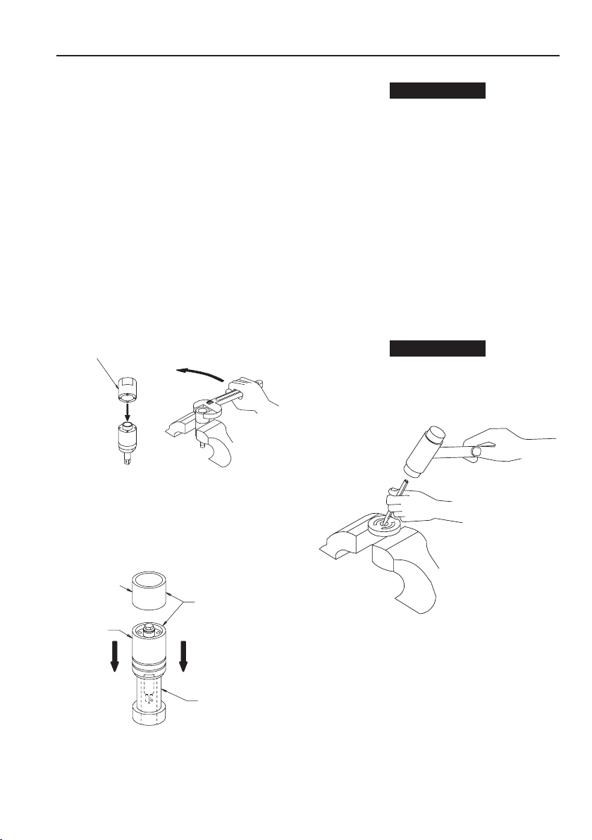
13. Insert the hex end of the Rear Liner Cover into the Disassembly
Arbor from the Tool Kit and stand it on a workbench with the
Drive Shaft upward.
14. Install the Front Liner Cover Assembly over the Drive Shaft and
against the Liner. Make certain the Torque Adjustment Screw
(72) aligns with the proper piston stop opening that was marked
during assembly.
15. Install the two Liner Cover Seals (48) in the grooves inside the
Liner Housing (47) near the end with the external wrench ats.
16. Place the Liner Housing, Seal end trailing, over the assembled
Liner. Make certain the notch in the trailing end face of the
Housing aligns with the Oil Plug (73) in the Front Liner Cover.
Use the Pressing Sleeve from the Tool Kit to press the Housing
over the Seals and into position. Do not Damage the Seals during
installation.
17. Grasp the ats of the Liner Housing in vise jaws and using the
Spanner Plug furnished with the Tool Kit and a torque wrench,
install the Housing Cap, castellated end leading. This is a
left–hand thread; rotate the wrench counterclockwise to tighten
the Cap.Tighten the Cap on models 500PS3 and 700PS3 between
9.4 and 10.7 ft–lb (12.7 and 14.5 Nm) torque and on model
900PS4 between 10.7 and 12.1 ft–lb (12.7 and 16.4 Nm) torque.
18. Make certain the Drive Shaft rotates freely and then ll the
mechanism with uid and reassemble the tool as instructed in
the section, CHANGING THE MECHANISM FLUID.

6 47109533_ed1
Related Documentation
For additional information refer to:
Product Safety Information Manual 04584983.
Product Information Manual 47133053.
Parts Information Manual 47135686.
Manuals can be downloaded from www.ingersollrandproducts.com

Notes:

www.ingersollrandproducts.com
© 2010 Ingersoll Rand
This manual suits for next models
2
Other Ingersol Rand Power Tools manuals