molex 63823-5700 User manual

Hand Crimp Tool for HNF Female Terminals
Doc No: ATS-6382357HM elease Date: 07-15-11 UNCONTROLLED COPY Page 1 of 8
evision: A evision Date: 07-15-11
INSULATION
CRIMP
▲SEE NOTE
BRUSH
STRIP LENGTH
CONDUCTOR
CRIMP HEIGHT
CUT-OFF TAB
SEAM
BELL MOUTH
WIRE
WIRE
BEND DOWN
BEND UP
ROLLING
TWISTING
Application Toolin
Specification Sheet
Tool Kit
Order No. 63823-5770
Hand Crimp Tool
Order No. 63823-5700
FEATURES
% A full cycle ratcheting hand tool ensures complete crimps
% Ergonomically designed soft handles
% Precisely designed crimping profiles with simple contact positioning
% Easy handling due to outstanding force ratio
Tool kits are easily installed into the Hand Crimp Tool or the 63816-0300 Power Crimp Head which is installed
into the 63816-0200 (110 V) or the 63816-0250 (220 V) Battery Powered Tool.
Many different Tool kits can be used with a single Battery Powered Tool.
This tool is IPC/WHMA-A-620 Class 2 and oHS compliant.
SCOPE
Products: HNF Female Terminals for 1.0-2.5mm2 Standard thick wall Insulation Metric wires.
Terminal Series No.
Terminal Order No.
Wire Size Insulation Diameter Strip Len th
Reel Form Only
AWG
mm²
mm In. mm In.
94518
94518-0200
94518-0201
94518-0220
94518-0221
- 1.00
2.60-3.80
.102-.150
5.00-5.50
.197-.217
- 1.50
- 2.50
Customer to cut off terminal from reel: 0.60mm (.024”) maximum Cut-off Tab.
DEFINITION OF TERMS
TYPE 4C

Hand Crimp Tool for HNF Female Terminals
Doc No: ATS-6382357HM elease Date: 07-15-11 UNCONTROLLED COPY Page 2 of 8
evision: A evision Date: 07-15-11
▲Insulation Crimp Note:
Due to the terminal’s insulation grip design
and/or insulation diameter range, this tool
uses “overlap” form geometry in the
insulation punch. This produces an overlap
insulation crimp (A620 – compliant). While
the insulation punch profile may appear
“lopsided”, this is a normal condition for this
tool. See figure to the right. (Some tools with
multiple crimp pockets may not have the
“overlap” profile on all pockets).
CRIMP SPECIFICATION
After crimping, the conductor profiles should
measure the following (see notes below).
Terminal Series No. Bell Mouth Bend up Bend down Twist Roll Conductor Brush
mm In. De ree De ree mm In.
94518 0.20-0.40
.008-.016
3 3 4 8 0.50- 1.50
.020-.059
Seam: Seam shall not be open and no wire allowed out of the crimping area.
Terminal
Series No.
Wire Size Conductor Crimp Insulation Crimp Pull Force
Minimum
Profile
Hei ht Width Hei ht Width
AWG
mm2
mm In. mm In. mm In. mm In. N Lb C
B
A
94518
- 1.00
1.75-1.85
.069-.073
2.80-2.90
.110-.114
3.30-3.40
.130-.134
4.35-4.45
.171-.175
160
36.0
X
- 1.50
1.90-2.00
.075-.079
2.80-2.90
.110-.114
3.50-3.60
.138-.142
4.35-4.45
.171-.175
200
45.0
X
- 2.50
2.10-2.20
.083-.087
2.80-2.90
.110-.114
3.60-3.70
.142-.146
4.35-4.45
.171-.175
250
56.2
X
Tool Qualification Notes:
1. Pull Force should be measured with no influence from the insulation crimp.
2. The above specifications are guidelines to an optimum crimp.
Note:
A crimp height chart is provided with this manual as eference Only. Due to the wide range of wires, strands,
insulation diameters, and durometers, actual crimp height measurements may very slightly. An occasional,
destructive, pull force test should be preformed to check hand tool crimp. Pull Force value must exceed the
minimum pull force specifications listed.
CAUTION: Install only Molex terminals listed above with this tool. Do not crimp hardened objects as damage
can occur to the tool or die.
OVERLAP
INSULATION
CRIMP
OVERLAP FORM GEOMETRY
ANVIL
PUNCH
WIRE

Hand Crimp Tool for HNF Female Terminals
Doc No: ATS-6382357HM elease Date: 07-15-11 UNCONTROLLED COPY Page 3 of 8
evision: A evision Date: 07-15-11
ANVILS
POWER
CRIMP
HEAD
Fi ure 1
PUNCHES
M4 X 10 LONG
BHCS
M4 X 18 LONG
BHCS
SWING
LOCATOR
OPEN
PRESS DOWN
ON THE BRASS
PIVOT SHAFT
LIFT UP ON
THE LOCATOR
Fi ure 2
INSTALLATION
To install the Tool Kit into the Power Crimp Head
follow the steps below:
Anvils and Punches Installation
1. Insert the Anvils into the bottom slots of the
nest. Install the M4 x 10 long BHCS and
tighten in place.
2. Insert the Punches into the top slots of the nest.
Install the M4 x 18 long BHCS and tighten in
place. See Figure 1.
Locator Installation and Removal
Follow the steps below to install or replace the locator. See Figure 2.
To install the locator
1. Position the locator with the hole over the brass pivot shaft and snap
it into place.
To remove the locator
1. Open the crimp hand tool and unlock the locator latch.
2. Swing the locator open and away from the hand tool.
3. Firmly press down on the brass pivot shaft with your thumb, while
pulling the locator up. Slip the locator off the top of the brass pivot
shaft.
OPERATION
Open the tool by squeezing the handles together, at the end of the closing
stroke, the ratchet mechanism will release the handles, and the hand tool
will spring open.
Crimpin Terminals
1. Select the desired terminal listed in the preceding
charts.
2. Unlock the locator latch and swing the terminal locator
away from the crimp tool shown in Figure 3 and 4.
3. Press down on the wire stop on the locator as shown in
Figure 4. Insert the proper terminal into the proper nest
opening. Make sure when choosing the nest opening, it
will correspond with the correct profile on the hand tool.
Fi ure 3
LATCH LOCKED
LATCH UNLOCKED

Hand Crimp Tool for HNF Female Terminals
Doc No: ATS-6382357HM elease Date: 07-15-11 UNCONTROLLED COPY Page 4 of 8
evision: A evision Date: 07-15-11
SWING OPEN
TERMINAL
PUSH HERE TO
OPEN WIRE STOP LOCATOR
TERMINAL
IN PLACE
Fi ure 4
LOCATOR LATCH
IN OPEN POSITION
HANDLE
OPEN
LOCATOR
CLOSED
Fi ure 5
TERMINAL
PUSH HERE TO
OPEN WIRE STOP
Fi ure 6
WIRE IN TERMINAL
JAWS
PARTIALLY
CLOSED
WIRE AGAINST
WIRE STOP
4. eturn the locator to closed position. Make sure the locator latch is in lock position. Insert the proper wire
over the terminal. See Figure 5. Gently touch the wire stop with the end of the wire and align with the grips on
the terminal. See Figure 6 and 7.
5. Compress the terminal by squeezing the tool handles
until the ratchet mechanism cycle has been
completed. elease handles to open the jaws.
6. Unlock the locator latch and swing the locator open.
7. emove the crimped terminal from the terminal
locator by pressing down on the wire stop and gently
pulling on the wire.
8. Visually inspect the crimped terminal for an
acceptable crimp.
Note: The tamper proof ratchet action will not release the tool until it has been fully closed.
Fi ure 7
WIRE
INSULATION
PUNCH
CONDUCTOR ANVIL
LOCATOR
INSULATION ANVIL
WIRES AGAINST
LOCATOR STOP
CONDUCTOR
PUNCH
TERMINAL

Hand Crimp Tool for HNF Female Terminals
Doc No: ATS-6382357HM elease Date: 07-15-11 UNCONTROLLED COPY Page 5 of 8
evision: A evision Date: 07-15-11
For the Battery Power Tool:
1. Cycle the Battery Power Tool to crimp the
terminal to the wire.
2. emove the crimped terminal from the
terminal locator by pressing down on the
wire stop and gently pulling on the wire.
3. Visually inspect the crimped terminal for an
acceptable crimp.
Maintenance
It is recommended that each operator of the tool
be made aware of, and responsible for, the
following maintenance steps:
1. emove dust, moisture and other contaminants with a clean brush, or soft, lint-free cloth.
2. Do not use any abrasive materials that could damage the tool.
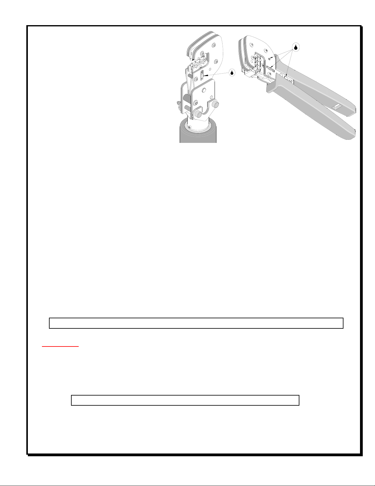
3. Make certain all pins; pivot points and bearing surfaces in the tool head are protected with a thin coat of high
quality machine oil. Do not oil excessively. This tool was engineered for durability, but like any fine piece of
equipment, it needs cleaning and lubrication for a maximum service life of trouble-free crimping. The use of
light oil, such as 30 weight automotive oil, every 5,000 crimps or monthly, will significantly enhance the tool life
and ensure a stable calibration. See Figure 8A or 8B for lubrication points.
4. Store the tool in a clean and dry area when not in use.
Miscrimps or Jams for Crimp Hand Tools Only (See Figure 11)
Should this tool ever become stuck or jammed in a partially closed position, Do Not force the handles open or
closed. The tool will open easily by rotating the small slotted screw marked with an arrow. See Figure 11.
Warranty
This tool kit is for electrical terminal crimping purposes only. This tool kit is made of the best quality materials. All
vital components are long life tested. All tools are warranted to be free of manufacturing defects for a period of 30
days. Should such a defect occur, we will repair or exchange the tool kit free of charge. This repair or exchange
will not be applicable to altered, misused, or damaged tools.
CAUTION: Molex crimp specifications are valid only when used with Molex terminals and tooling.
CAUTIONS
1. Manually powered hand tools are intended for low volume or field repair. This tool is NOT intended for
production use. epetitive use of this tool should be avoided.
2. Insulated rubber handles are not protection against electrical shock.
3. Wear eye protection at all times.
4. Use only the Molex terminals specified for crimping with this tool.
CAUTION: epetitive use of this tool should be avoided.
Certification
Molex does not certify or re-certify commercial grade hand tools but rather supplies the following guidelines for
customers to re-certify hand tools.
LUBRICATION
POINTS
(BOTH SIDES)
LIGHT OIL
(EVERY MONTH
OR
5,000 CRIMPS)
Fi ure 8A
Fi ure 8B

Hand Crimp Tool for HNF Female Terminals
Doc No: ATS-6382357HM elease Date: 07-15-11 UNCONTROLLED COPY Page 6 of 8
evision: A evision Date: 07-15-11
% This tool is qualified to pull force only. To re-certify, crimp a terminal to a wire, which has been stripped
12.7mm (1/2”) long, so there is no crimping of the insulation. Pull the terminal and wire at a rate no faster than
25mm (1.00”) per minute. See the Molex web site for the Quality Crimp Handbook for more information on pull
testing.
% When the hand tool is no longer capable of achieving minimum pull force, it should be taken out of service and
replaced.
% This tool is very difficult to disassemble and reassemble. Customer repair is not recommended.
The chart below shows all applications for this Tool Kit.
Tool Kit
Order No.
Tool
Order no.
Tool
Description
Power Head
Order No.
Adapter
Description
Fi ure
No.
63823-5770
63810-1050
Hand Crimp Frame (Short) N/A N/A 9
63810-1000
Hand Crimp Frame (Long) N/A N/A 9
63816-0200
Battery Power Tool (110 V)
63816-0300 Power Crimp Head
10
63816-0250
Battery Power Tool (220 V)
63816-0300 Power Crimp Head
10
Applications for the Tool Kit
Hand Crimp Tool Battery Powered Tool
Fi ure 9 Fi ure 10
WARNING: NEVER operate service, install tool kits, or adjust the Power Crimp Head without proper
instruction and without first reading and understanding the instructions in the proper Manual or
Specification Sheet. See Chart above for the correct Manual or Specification Sheet.
WARNING: NEVER install tooling or service this tool while it is into any power source. Make sure the
power is turned off.
CAUTION: Keep fingers away from the crimping area when operating this tool. It may cause severe injury.
CAUTION: Wear safety glasses when operating or serving this tool.
POWER
CRIMP
HEAD
LOCKING PINS
BATTERY
POWERED
TOOL
TOOLING KIT
HAND CRIMP
FRAME LONG
AND SHORT
TOOLING KIT

Hand Crimp Tool for HNF Female Terminals
Doc No: ATS-6382357HM elease Date: 07-15-11 UNCONTROLLED COPY Page 7 of 8
evision: A evision Date: 07-15-11
RATCHET
RELEASE SCREW
Fi ure 11
M4 X 8mm
LONG BHCS
2
1
1
M4 X 18mm
LONG BHCS
M4 X 10mm
LONG BHCS
2
3
WITH TOOL KIT
LOCATOR ONLY
HAND TOOL PARTS LIST
Item Number Order Number Description Quantity
1 63810-1000 Hand Crimp Frame (Long) 1
2 63823-5770 Tool Kit with Locator 1
3 63823-5775 Locator (only) EF

Hand Crimp Tool for HNF Female Terminals
Doc No: ATS-6382357HM elease Date: 07-15-11 UNCONTROLLED COPY Page 8 of 8
evision: A evision Date: 07-15-11
Fi ure 12
1
2
2
M4 by 8 Lon
BHCS
M4 by 18 Lon
BHCS
M4 by 10 Lon
BHCS
1
POWER HEAD PARTS LIST
Item Order No En ineerin No. Description Quantity
1
63816-0300 63816-0300 Power Crimp Head 1
2
63823-5770 63823-5770 Tool Kit with Locator 1
http://www.molex.com
This manual suits for next models
1
Table of contents
Other molex Power Tools manuals

molex
molex RAST 5.0 Arbor Press Terminator User manual

molex
molex 43375 User manual

molex
molex 69020-1908 User manual

molex
molex TM2000 User manual

molex
molex Mini Mi2 User manual

molex
molex 63827-8800 User manual

molex
molex 63827-2000 User manual

molex
molex Mini Mi2 User manual

molex
molex 64000-0041 User manual

molex
molex 63816-0200 User manual

molex
molex 69020-2025 User manual

molex
molex TM-3000 User manual

molex
molex TM42 User manual

molex
molex 63811-3300 User manual

molex
molex 63816-0270 User manual

molex
molex TM2000 User manual

molex
molex 11-31-6356 User manual

molex
molex 207129 Series User manual

molex
molex 63816-0100 Manual

molex
molex TM-3000 User manual