Ingrasys iED N Series User manual

iED N Series
- i -
Version: V1.00
Date: February 28, 2014
This document contains proprietary and confidential information of Ingrasys. All rights and titles hereto
remain with Ingrasys. The recipient shall keep this document in strict confidence and shall use this document
in the manner and solely for the purposes expressly agreed to by Ingrasys. The recipient shall not disclose
or allow access to this document, in whole or in part, to third parties, nor use it for the benefit of the recipient
or third parties. The recipient shall not change this document in form or substance by any means, including
without limitation, decompilation, reproduction, revision, or amendment.

Table of Contents
1.1About this Manual............................................................. 1
1.2Safety Precautions............................................................ 1
2.1Features........................................................................ 2
2.2System Requirements........................................................ 2
2.3Package Contents ............................................................ 3
2.4Hardware Overview........................................................... 4
2.4.1Dimensions .................................................................... 4
2.4.2Front View...................................................................... 4
2.4.3Rear View ...................................................................... 4
3.1Connect to the main power.................................................. 5
3.2Connecting to a Network..................................................... 6
3.3Connecting to iED S-201 (RS485 HT sensor) ............................ 6
3.4Connecting DI/DO/AI to iED N-002......................................... 7
4.1Configuring network settings via iED upgrade tool....................... 8
5.1Login.......................................................................... 10
5.2Information................................................................... 10
5.2.1System Overview ........................................................... 10
5.2.2Network Connection ........................................................ 12
5.2.3Alarm List..................................................................... 12
5.3Network Management...................................................... 13
5.3.1TCP/IP........................................................................ 14
5.3.2IPv4 Setting.................................................................. 14
5.3.3IPv6 Address................................................................. 15
5.3.4Accessible IP Setting ....................................................... 15
5.3.5Security....................................................................... 17
5.3.6Network Service............................................................. 17
5.4System Management....................................................... 19
5.4.1General Setting.............................................................. 19
5.4.2Change Password .......................................................... 21
5.4.3Maintenance................................................................. 21
5.4.4Import/Export ................................................................ 22
5.5SNMP Management ........................................................ 23
5.5.1SNMP Setting................................................................ 23
5.5.1SNMP Agent ................................................................. 23
5.5.2SNMP Trap Setting ......................................................... 24
5.6Email Management ......................................................... 25
5.6.1Configure SMTP Server.................................................... 25

5.6.1SMTP Setting................................................................ 25
5.6.2Email Notification Setting .................................................. 26
5.7User Management .......................................................... 28
5.8Sensor Management ....................................................... 29
5.8.1Gateway Management ..................................................... 29
5.8.1Zigbee Setting ............................................................... 29
5.8.2RS485 Setting ............................................................... 30
5.8.3Sensor Management ....................................................... 30
5.8.4Sensor Overview............................................................ 30
5.8.5Sensor Configuration....................................................... 31
5.8.6Sensor Upgrade............................................................. 37
5.8.7Cloud Management......................................................... 37
5.9Event Action.................................................................. 38
5.10Log ............................................................................ 38
5.10.1System Log .................................................................. 38
5.10.2Event Log .................................................................... 39
5.10.3History Log................................................................... 41
5.10.4Syslog Setting ............................................................... 42
5.10.5System/Event Log........................................................... 42
5.10.6History Log................................................................... 43
6.1LED indicators............................................................... 45
6.2Specifications................................................................ 46


1. Preface
1.1 About this Manual
This manual provides instructions for installing the iED N-002 on your network and for configuring
the network. It is suggested to read this manual according to the sequence of the Table of Contents
in order to avoid any setting errors.
1.2 Safety Precautions
1. Do not attempt to disassemble the equipment in order to avoid electrical shock or irreparable
damage to internal parts.
2. Do not place the equipment outdoors in rain or in locations with high humidity in order to protect
electronic components from short circuit.
3. Installation and maintenance of this equipment should be handled by professional technicians.
4. Make sure the equipment and its accessories are secured properly to prevent it from falling to the
ground and being damaged.
5. Use only the power adaptor and accessories included in the package, alternative brands may
damage the equipment.
6. Follow the instructions in this manual to connect the power adaptor and avoid improper use of
the equipment. Make sure all the cables are connected correctly before turning on the power.
7. Do not use any organic solutions or corrosive detergents to clean the exterior of the equipment.
To clean the equipment, first turn off the power. Use a cloth that has been lightly dampened in
water to clean the exterior.
8. Do not use the equipment in the following environments:
●Humidity higher than 100%.
●Temperature higher than 70°C or lower than -20°C.
●Near objects which transmit strong electromagnetic waves (e.g. televisions or radios).
●Locations subject to violent shaking.
●Locations that are damp or that come in contact with water.

User’s Manual
2. Getting Started
2.1 Features
Real-time temperature/humidity and other environmental conditions monitoring
Comprehensive environment conditions management and flexible configuration via Web
Brower or SNMP or Modbus over TCP/IP
Automatic event notification via E-mail and SNMP Trap
Automatically assigned IP via DHCP or BOOTP
System Security: IP-based filtering and password protection for operation and
administration
Support SSL V3 and SSH V2 protocol
Automatically records and displays environment events, warning, and time stamps
Configuration utility simplifies the firmware upgrade process
Settable thresholds for all sensors
System, data, and event logging features
Auto-sense to works in the 10/100Mbps Fast Ethernet network environment
Supports four digital-inputs for normal open/close sensors
Supports four digital-outputs to trigger extended devices by events
Supports four DC voltage/current configurable sensors
Rack mountable
Quick and easy installation (Hot-swappable)
Address-specific IP security masks prevent unauthorized source from accessing iED N-
002 through the network
2.2 System Requirements
Operating System: Windows XP, 2003, Vista, 2008, 7, 2012, 8 and above.
Internet Browser: Microsoft IE 11.0, Firefox 26.0, Chrome 32.0.1700.107 m or above.

2.3 Package Contents
Make sure that your package has the following items. If any of items are missing or damaged,
contact your nearest service center or vendor.
Item Models/variants/notes
IP-based I/O controller iED N-002
AC Adapter 100~240 V ; 50/60Hz x 2
CD-ROM Manual, QIG, Modbus address, Upgrade Tool
QIG Quick Installation Guide
Terminal Block Power (2 pin) x1
RS-485(3 pin) x 1
I/O (4 pin) x 32
iED N-002 AC Power code x 2 CD-ROM with manual
and software
Quick Installation Guide 3 Pin Removable
Terminal Block 4 Pin Removable
Terminal Block
2 Pin Removable
Terminal Block

User’s Manual
2.4 Hardware Overview
2.4.1Dimensions
2.4.2 Front View
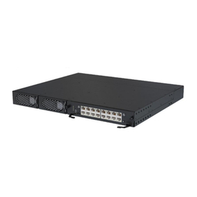
2.4.3 Rear View

3. Installation and Connection
To install the iED N-002 on a network and change its configuration, you need a workstation
running Microsoft Windows (XP, 7 or later) and
connect the iED N-002 to LAN.
3.1 Connect to the main power
Insert the end of the power connector to the AC-In jack on the rear of the iED N-002. Connect the
other end into a power socket (100 ~ 240V).

User’s Manual
3.2 Connecting to a Network
The iED N-002 can be connected to an Ethernet network with a RJ-45 cable as shown below.
Connect the iED N-002 to an Ethernet hub or switch with a RJ-45 cable.
3.3 Connecting to iED S-201 (RS485 HT sensor)
The iED N-002 can be connected to iED S-201 (RS485 HT Sensor) with 3 wires by RS485 for
communication and with 2 wires for power as shown below.

3.4 Connecting DI/DO/AI to iED N-002
The iED N-002 can be connected to 32 sets of sensor (enclose closure sensor) on Digital Input
and 16 sets of devices on Digital Output and 16 sets of (4~20 mA) sensor on Analog Input that
each sets of DI/DO/AI connected via 2 wires. Analog-in of No.4 I/O module is connect waterleak
sensor.
Waterleak

User’s Manual
4. Configuration
4.1 Configuring network settings via iED upgrade tool
When you have installed the iED N-002 via LAN (refer to Chapter 3), you can configure the
network setting of “iED N-002” via “iED Upgrade Tool” by the following steps.
1. Make sure you have a PC with the TCP/IP network installed.
2. Find “iED Upgrade Tool v1.00.exe” from CD-ROM
3. Double click icon for installation
4. After installation completed, please perform “iED Upgrade Tool”
5. Clicking Discover icon to find out the device in the network.
6. One entry was selected, and then to click Set IP icon

7. IP address of iED N-002 set as the same IP segment of your PC/network.
8. Open browser then input the IP address of iED N-002

User’s Manual
5. Managing iED N-002 via web browser
5.1 Login
The mouse moves on the icon of Login then click left button.
Input correct User Name and Password (default is admin / admin)
5.2 Information
There are three sub-menus under Information.
System Overview
Network Connection
Alarm List
5.2.1 System Overview
This page is default homepage of iED N-002 and gives System Information and Network
Information.

4.1.1.1 System Information
System Information shows “System Name”, “Serial Number”, “Firmware Version” and “System
Elapsed Time”.
System Name
This field shows the system name of iED N-002
Serial Number
This field shows the serial number
Firmware Version
This field shows the reversion of iED N-002
System Elapsed Time
This field shows the iED N-002 time setting. This value is displayed in the DD hh:mm:ss
(i.e., 1 day 05h: 34m: 20s)
4.1.1.2 Network Information
“Network Information” shows IPv4 and IPv6 address and MAC address.
IPv4 address
This field shows the present IPv4 address. For example: 192.168.54.152
IPv6 address
This field shows the present IPv6 address. For

User’s Manual
example:2001:1234:2345:3456:67890:2e0:d8ff:feff:b406/64
MAC Address
This field shows the present MAC address. For example: 00:E0:D8:FF:B5:4E
5.2.2 Network Connection
This page shows Connection Table and IP Filter Table
4.1.2.1 Connection Table
It will display “Total TCP Connection numbers” and “Source Host Address” (IPv4 or IPv6) and
“Connection Type” (HTTP, HTTPs, SSH…, and so on) and “Login username” in the table.
4.1.2.2 IP Filter Table
It will display Allow or Deny IPv4 or IPv6 address in the IP Filter Table.
Note: the accessible IP list must be enabled
5.2.3 Alarm List
This page lists the present total active alarms and all alarms at Alarm Table that includes “Alarm ID”
and “Alarm Time” and “Sensor Name” and “Alarm Description”.

Number of Active Alarms
This field shows the number of current active alarms.
Alarm ID
This field shows the sequential number that indicates the sequence of alarm activation. This
number will be reset after the iED N-002 rebooted.
Sensor Name
This field shows the present sensor’s name that the alarm is triggering.
Alarm Description
This field shows the complete alarm description.
5.3 Network Management
There are four sub-menus under Information.
TCP/IP
Accessible IP Setting
Security
Network Service

User’s Manual
5.3.1 TCP/IP
This page allows the administrator to set the local network configuration parameters.
Enable DHCP
This is the parameter enabling the Dynamic Host Configuration Protocol (DHCP)
process. This protocol are used to obtain a dynamic IPv4 address from a DHCP server
otherwise not.
5.3.2 IPv4 Setting
IP Address
This field allows the administrator to view the present setting or set the IPv4 address of
iED N-002 and only accept “dotted decimal notation” format (i.e., 192.168.60.229).
Subnet Mask
This field allows the administrator to view the present setting or set the subnet mask of
iED N-002 and only accept “dotted decimal notation” format (e.g.: 255.255.255.0)
Gateway
This field allows the administrator to view the present setting or set the IPv4 address of
gateway and only accept “dotted decimal notation” format (e.g.: 192.168.1.254)
Primary DNS Server
This field allows the administrator to set the IPv4 address of the network DNS server and
only accept “dotted decimal notation” format (e.g.: 8.8.8.8).

Secondary DNS Server
This field allows the administrator to set the IPv4 address of the network DNS server and
only accept “dotted decimal notation” format (e.g.: 8.8.8.8).
5.3.3 IPv6 Address
Enable IPv6
This check box is the parameter enabling allows IPv6 functionality.
Configuration
This field allows the administrator to select the configuration type:
Automatic: IPv6 address,Prefix Length,Router and DNS that all will depend on IPv6
router or DHCPv6.
Manual: the administrator could manually set IPv6 address, Prefix Length, Router and
DNS.
IP Address
If configuration as Manual, this field allows the administrator to view the present setting or
set the IPv6 address of iED N-002 and only accept “hexadecimal” format (i.e.,
2001:1234:100:f101:2e0:d8ff:feff:b522). If configuration as automatic, this field will be
gray and unable to set and shows the value from IPv6 router or DHCPv6 assigned.
Prefix Length
If configuration as Manual, this field allows the administrator to view the present setting or
set the Prefix Length of iED N-002 and only accept an integer between 1-128. (i.e.,
2001:db8:abcd:0012::0/64 from:2001:db8:abcd:0012:0000:0000:0000:0000
- 2001:db8:abcd:0012:ffff:ffff:ffff:ffff). If configuration as automatic, this field will be gray
and unable to set and shows the value from IPv6 router or DHCPv6 assigned.
Router
If configuration as Manual, this field allows the administrator to view the present setting or
set the IPv6 address of router and only accept “hexadecimal” format (i.e.,
2001:1234:100:f101:2e0:d8ff:feff:b522). If configuration as automatic, this field will be
gray and unable to set and shows the value from IPv6 router or DHCPv6 assigned.
Primary DNS Server
This field allows the administrator to set the IPv6 address of the network DNS server and
only accept ““hexadecimal” format (i.e., 2001:1234:100:f101:2e0:d8ff:feff:b522).
Secondary DNS Server
This field allows the administrator to set the IPv6 address of the network DNS server and
only accept “hexadecimal” format (i.e., 2001:1234:100:f101:2e0:d8ff:feff:b522).
5.3.4 Accessible IP Setting
This page allows the administrator to set Accessible IP list.

User’s Manual
Enable the accessible IP list
This check box is the parameter enabling accessible IP list.
Accessible IP list
Clicking will show ADD dialog, once one or more entries have been selected, it is not
available.
IP Address
This field allows the administrator to set the IPv4/IPv6 address and only accept
“dotted decimal notation” format (i.e., 192.168.60.229) or “hexadecimal” format (i.e.,
2001:1234:100:f101:2e0:d8ff:feff:b522).
Prefix Length
This field allows the administrator to set the Prefix Length and only accept an integer
between 0-32 (IPv4) or 0-128 (IPv6).
Action
Allow, this IP or IP segment could be accessed iED-N002.
Deny, this IP or IP segment could not be accessed iED-N002.
One or more entries have been selected and to click , they will be deleted from list.
One of entries have been selected and to click , the Modify dialog will appear.
This manual suits for next models
1
Table of contents
Popular Controllers manuals by other brands
Huawei
Huawei ECC800-Pro user manual

Saswell
Saswell SEA801-APP Installation and user guide

Siemens
Siemens SIPART Series operating instructions
Metso
Metso VALVCON QX Series Installation maintenance and operating instructions

Novus
Novus XL6 quick start guide

ADB Safegate
ADB Safegate CRE 2.5 installation manual


