Iniven IAFT-30ADSP User manual

IAFT-30ADSP
5 Columbia Road, Somerville, NJ 08876
Toll Free: (800) 526-3984 | Phone: (908) 722-3770 | Fax: (908) 722-5461
COMPACT SINGLE ANALOG TRANSMITTER

DESCRIPTION
The IAFT-30ADSP is a compact single analog transmitter for use in telemetry systems. Inside of the chassis are three
different modules mounted to the common terminal board in the back of the unit. These modules include: IT-98
Programmable Transmitter, IP-98 Power Supply, and I/O 40T Analog I/O Module.
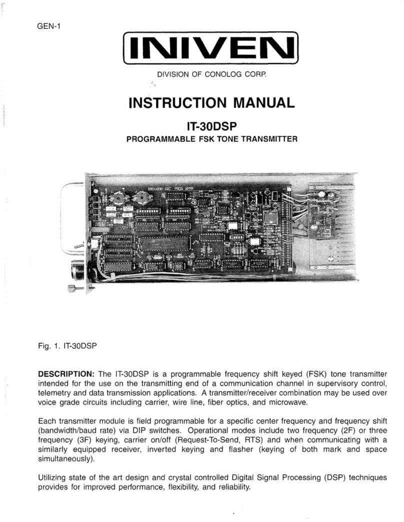
IT-98DSP
Transmitter Module
FEATURES
•Optical or voltage keying inputs
provided on each unit.
•Front panel level adjustment
•DIP switch programmable
•Modular cost saving design
•12 Year Warranty
DESCRIPTION
The IT-98DSP is a programmable
frequency shift keyed (FSK) tone
transmitter intended for use on the
transmitting end of a communication
channel in supervisory control,
telemetry and data transmission
applications. It may be used over
voice grade circuits including carrier,
wire line, fiber optics, and
microwave.
Each transmitter module is field
programmable for a specific center
frequency, frequency shift
(bandwidth/baud rate) and mode of
operation via DIP switches.
Operational modes include two
frequency (2F) or three frequency
(3F) keying, carrier on/off (Request-
To-Send, RTS) and when
communicating with a similarly
equipped receiver, inverted keying
and flasher (keying of both mark and
space simultaneously).
IP-98
Power Supply Module
FEATURES
•Wide Range of Input Voltages
•5000 Vdc Isolation
•Modular cost saving design
•12 Year Warranty
DESCRIPTION
The IP-98 and IP-98-1U are a series
of Regulated Switching Power
Supplies for use within the 3U, 1U,
and compact style chassis.
The IP-98 is available in a wide
range of input voltages; 115 Vac,
125 Vdc, 48 Vdc, 24Vdc, and 12 Vdc
each providing regulated +5 V, +15 V
& -15 Vdc outputs. The IP-98-
115Vac, IP-98-125Vdc, IP-98-48Vdc,
and IP-98-24Vdc provide 55 Watts of
power standard, while the IP-98-
12Vdc and aIl IP-98-1 U versions
used in the 1U chassis deliver 20
Watts of power.
All supplies except the 12 Vdc units
have 5000 Vdc isolation from input to
output and meet both SWC
Standards ANSI/IEEE C37.90.1978
& C37.90a-1974.
I/O 40T
Analog I/O Module
FEATURES
• Uni-polar or bi-polar I/O’s
• Wide range of I/O’s
• High accuracy & stability
• Differential input for ground loop
noise rejection
• Form C relay output
• 12 year warranty
DESCRIPTION
The I/O 40T is an accurate and
stable voltage (or current) to
frequency converters. The I/O 40T
when used in conjunction with
INIVEN’s 98 Series FSK transmitter,
is the transmitting side of an analog
telemetry system.
Various inputs to the unit can be
accommodated. Bi-polar and uni-
polar voltage or current inputs can be
accepted.
The output of the I/O module is a
square wave which modulates an
FSK tone transmitter alternately
between mark and space
frequencies at a rate within a 5-30Hz
range. Standard ranges are 5-25Hz,
10-30Hz and 18-30Hz.

SPECIFICATIONS
IT-98DSP Transmitter Module
Output Level
Front panel adjustable to +5 dBm
Output Impedance
15 KΩminimum
Keying Inputs
Mark, Space, and Request to Send (RTS/carrier on/off)
High impedance 3-30 Vdc
Optically coupled 5-50 Vdc
Optional optically coupled inputs to 150 Vdc
Keying Methods
CMOS, TTL, RS232, Dry contact, Opto-isolation, Voltage
(various I/O interfaces available)
Operating Frequency Range
200-3800 Hz
Operating Bandwidths
50, 60, 85, 120,170, 240, 300 or 600 Hz Standard
Data Level Outputs
Clear -To-Send (CTS) .5 ms delay @ +5 Vdc
Indicators
Front panel mounted for mark, space, RTS, and CD/carrier on
CTS
Spectral Purity
Harmonic content: 70dB below carrier level.
Spurious signals at adjacent channels: 70dB below carrier
Bias Distortion
Less than 7% with channel keyed in accordance to
programmed bandwidth, back to back Transmitter/Receiver.
Environmental Requirements
Temperature Range: -30 to +70 C (-22 to +158 F)
Relative Humidity: 95% maximum, non-condensing at 40 C
(104 F).
Power Requirements
+5 Vdc +/- 5% (4.75 to 5.25 Vdc) 95ma @ 5 V
+12 Vdc +/- 35% (7.8 to 16.2 Vdc) 13.9 ma @ 15 V
-12 Vdc +/- 35% (7.8 to 16.2 Vdc) 11.5 ma @ 15 V
Physical
Weight: .5lbs (.23 Kg)
Dimensions:
• 1.0” (25.4 mm) W
• 5.04” (128 mm) H
• 9.76” (248 mm) D
IP-98 Power Supply Module
Input Voltages
115 Vac 86 Vac to 144 Vac
125 Vdc 94 Vdc to 156 Vdc
48 Vdc 36 Vdc to 60 Vdc
24 Vdc 18 Vdc to 30 Vdc
12 Vdc 9.6 Vdc to 14.4 Vdc
Output Voltages
+ 5V supply +/- 1% 5 amp
+ 15V supply +/- 20% 3 amp
- 15V supply +/- 20% 2 amp
Total Output Power
55 Watts 20 Watts
IP-98-115Vac IP-98-12Vdc
IP-98-125Vdc IP-98-1U-115Vac
IP-98-48Vdc IP-98-1U-125Vdc
IP-98-24Vdc IP-98-1U-48Vdc
IP-98-1U-24Vdc
IP-98-1U-12Vdc
Output Ripple
+ 5V 20mV peak Maximum
+15V 50mV peak Maximum
- 15V 100mV peak Maximum
Efficiency
80% at full load typical
12Vdc version 60% at full load typical
Isolation
5000 Vdc from input to output
1000 Vdc from input to output on 12
volt supply.
Surge Withstand Capability
ANSI/IEEE C37.90.1978 & C37.90a-1974 except
12 Vdc supplies
Environmental Requirements
Temperature Range: -30 degrees C to +70 degrees
C (-22 to +158 F)
Relative Humidity: 95% maximum, non condensing
at 40 C (104 F)
Physical
Weight: 1.4 Ibs (.64 kg).
Dimensions
• 2.8 inches (71 mm) W
• 5.04" (128 mm) H
• 9.76" (248 mm)

I/O 40T Analog I/O Module
Environmental Requirements
Temperature Range: -30 to +70 C (-22 to +158 F)
Relative Humidity: 95% maximum, non-condensing at 40 C (104 F).
Power Requirements
+15 Vdc 15 mA (I/O 40T & I/O 40R)
-15 Vdc 7 mA (I/O 40T), 5ma (I/O 40R)
Accuracy
Setable to .1 % of span
Linearity
<0.1 % of span
Drift
<0.005% per degree C
<0.2% over 6 months
<0.1% per volt of supply voltage change
<30 micro volts per degree C input offset
Input DC Voltage Range
±50mV to ±5V
Input DC Current Range
±0.1mA to ±50mA
Input Common Mode Rejection
>45db with up to 3V peak common mode noise
Input Resistance
>1 MQ for voltage input
Output Frequency Range
5-25Hz, 10-30Hz & 18-30Hz standard (call factory for specials)
Output Voltage
>10V peak-to-peak square wave
Physical
Weight: .5lbs (.23 Kg)
Dimensions
• 1.0" (25.4 mm) W
• 5.04" (128 mm) H
• 3.30" (83.8 mm) D


INIVEN™
INSTRUCTION MANUAL
IP-98 AND IP-98-1 U
POWER SUPPLIES
Fig. 1. IP-98 POWER SUPPLY
DESCRIPTION: The IP-98 and IP-98-1 Uare a
series of Regulated Switching Power Supplies
for use within the "3U" and
"1
U" EURO style
chassis. The IP-98 is available
in
awide range
of input voltages; 115 Vac, 125 Vdc, 48 Vdc, 24
Vdc, and 12 Vdc each providing regulated
+5
V,
+15 V&-15 Vdc outputs. The IP-98-115Vac, IP-
98-125Vdc, IP-98-48Vdc, and IP-98:24Vdc pro-
vide 55 Watts of power standard, while the IP-
98-12Vdc andaIlIP-98-1Uversions used in the
1U chassis deliver 20 Watts of power. All sup-
plies exceptthe 12 Vdc units have 5000 Vdc iso-
lation from input to output and meet both SWC
Standards ANSI/IEEE C37.90.1978 &C37.90a-
1974.
FEATURES:
•Wide Range of Input Voltages.
•5000 Vdc Isolation on 24, 48, 125 Vdc &115
Vac.
•Cost Saving Design While Maintaining Reliability and Quality.
•Life Time Warranty.

20 Watts
IP-98-12Vdc
IP-98-1 U-115Vac
IP-98-1 U-125Vdc
IP-98-1 U-48Vdc
IP-98-1 U-24Vdc
IP-98-1 U-12Vdc
SPECIFICATIONS:
Input Voltages:
115 Vac 86
Vac
to 144 Vac
125 Vdc 94 Vdc to 156 Vdc
48 Vdc 36 Vdc to 60 Vdc
24 Vdc 18 Vdc to 30 Vdc
12 Vdc 9.6 Vdc to 14.4 Vdc
Output Voltages:
+5V supply +/- 1% 5 amp
+15V supply +/- 20% 3amp
-15V supply +/- 20% 2amp
Total
Output Power:
55 Watts
IP-98-115Vac
IP-98-125Vdc
IP-98-48Vdc
IP-98-24Vdc
Output Ripple:
+5V 20mV peak Maximum
+15V 50mV peak Maximum
-15V 100mV peak Maximum
Efficiency: 80% at full load typical
12Vdc version 60% at full load typi-
cal
Isolation: 5000 Vdc from input to output
1000 Vdc from input to output
on
12
volt supply.
Surge
Withstand
Capability:
ANSI/IEEE
C37.90.1978 &C37.90a-1974except
12 Vdc supplies.
Environmental Requirements:
Temperature Range: -30 degrees Cto +70 de-
grees C(-22 to +158
F)
Relative Humidity: 95% maximum, non condens-
ing at 40 C(104
F)
Physical:
Weight: 1.4 Ibs (.64 kg).
Dimensions: 2.8 inches
(71
mm) Wide by
5.04" (128 mm) High by 9.76" (248 mm)
Deep
Note: IP-98-1 Uhas aspecial front panel and is
intended for use
in
the 1U chassis only.
SAFETY
Standard safety precautions must be followed at all times when installing, oper-
ating, servicing, and repairing this equipment. INIVEN/CONOLOG CORP. assumes
no liability for failure to observe standard or specifically noted safety require-
ments
or
to use this equipment for purposes other than intended.
GROUNDING:
Asuitable ground is required to reduce the haz-
ard of shock. Referto the enclosed module, chas-
sis, and/or cabinet wiring diagram for ground
connection locations. '
ENVIRONMENT:
Operation of any electrical equipment
in
any area
containing gases, fumes, wet, or damp
is
apo-
tential safety hazard. Necessary precautions
.should be taken.
MANUAL:
Operators and maintenance personnel should
read this manual before installing the equipment
and placing it
in
service. Only properly trained
personnel with proper tools and equipment
should operate, maintain, repair, or service this
equipment.
SHOCK:
Potentially dangerous electrical shock can oc-
cur whenever working
on
this product. Protec-
tive measures and safety procedures should be
observed at all times.
NOTE:
The IP-98 Series of Power Supplies Contain High Voltages.
Do
Not Handle Com-
ponents With Power Applied to the Unit.
This manual suits for next models
2
Table of contents
Other Iniven Transmitter manuals
