Kimo TG 100 Instruction Manual

WITH or WITHOUT display
Features of the transmitter
Features of the housing
Temperature transmitter
TG 100
Part number
To order, just add the codes to complete the part number :
Example : TG100-VOA
Model : temperature transmitter TG 100 active sensor 0-10 V output, with
display and duct mount probe.
Transmitter / power supply / output
Display
OWith display
NWithout display
Mounting
ADuct mount
BTerminal block
TG100
-
Temperature
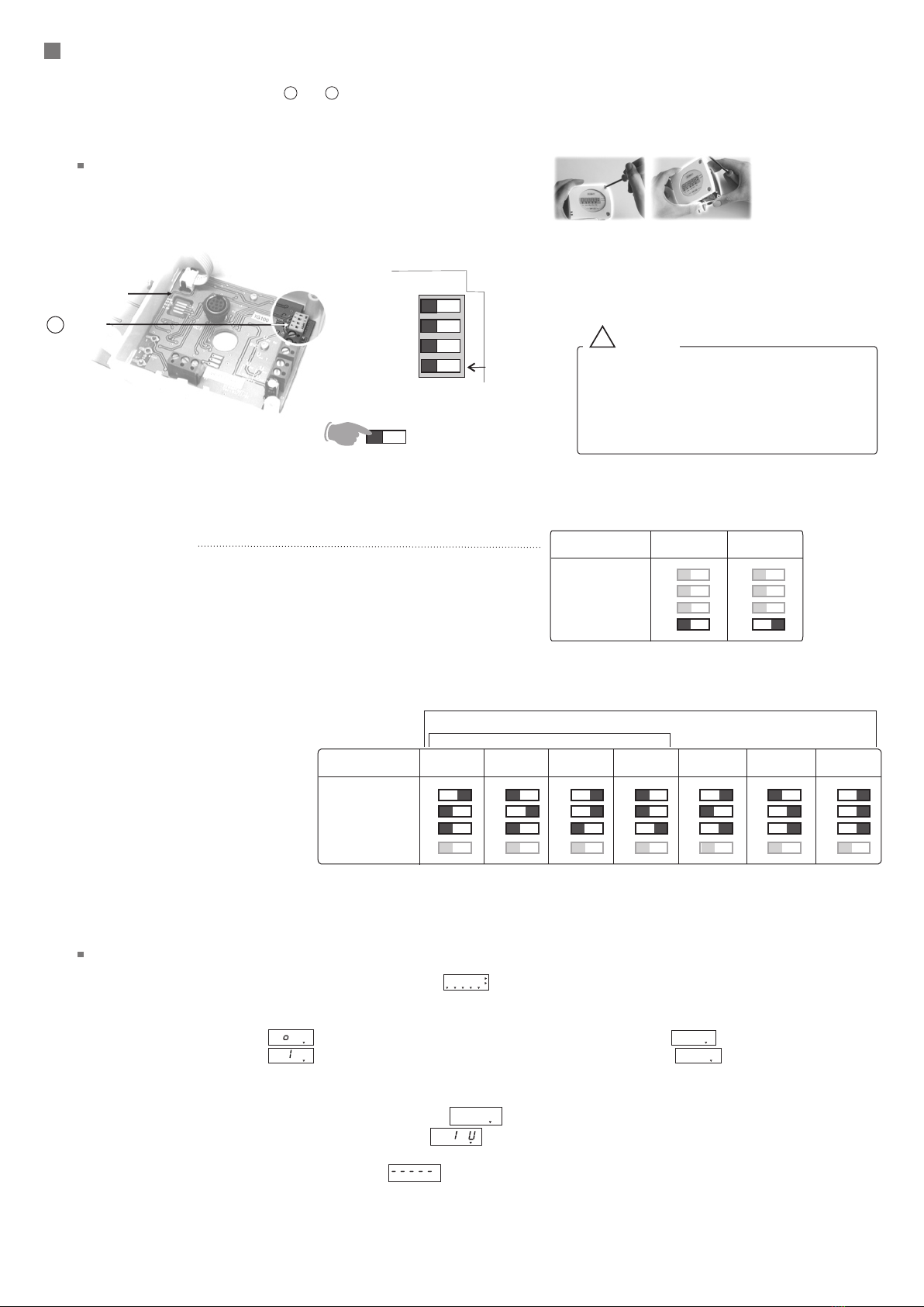
Measuring range ......................see chart ”Configuration”
Units of measurement .............°C, °F
Accuracy * ................................±0,5% of reading ±0,4°C (duct mount probe)
according to the probe (Pt 100 on terminal block)
Response time .........................1/e (63%) 5 sec. (duct mount probe)
according to the probe (Pt 100 on terminal block)
Resolution ................................0,1°C
Type of sensor..........................Pt 100 class A as per DIN IEC751
Type of fluid............................ air et neutral gases
• Duct temperature transmitter, TG100 type
• Measuring ranges from 0 to +50°C, -20 to +80°C, -50 to +50°C, 0 to +100°C,
0 to 200°C, 0 to +300°C, 0 to +400°C (according to model, see “Configuration”)
• 0-10 V output , active sensor, power supply 24 Vac/Vdc (3-4 wires) or
4-20 mA output , passive loop, power supply 18 to 30 Vdc (2 wires)
• ABS IP 65 housing, with or without display
• Quick and easy mounting “1/4 turn” system with wall-mount plate
Housing ...............................................ABS
Fire-proof classification.....................HB as per UL94
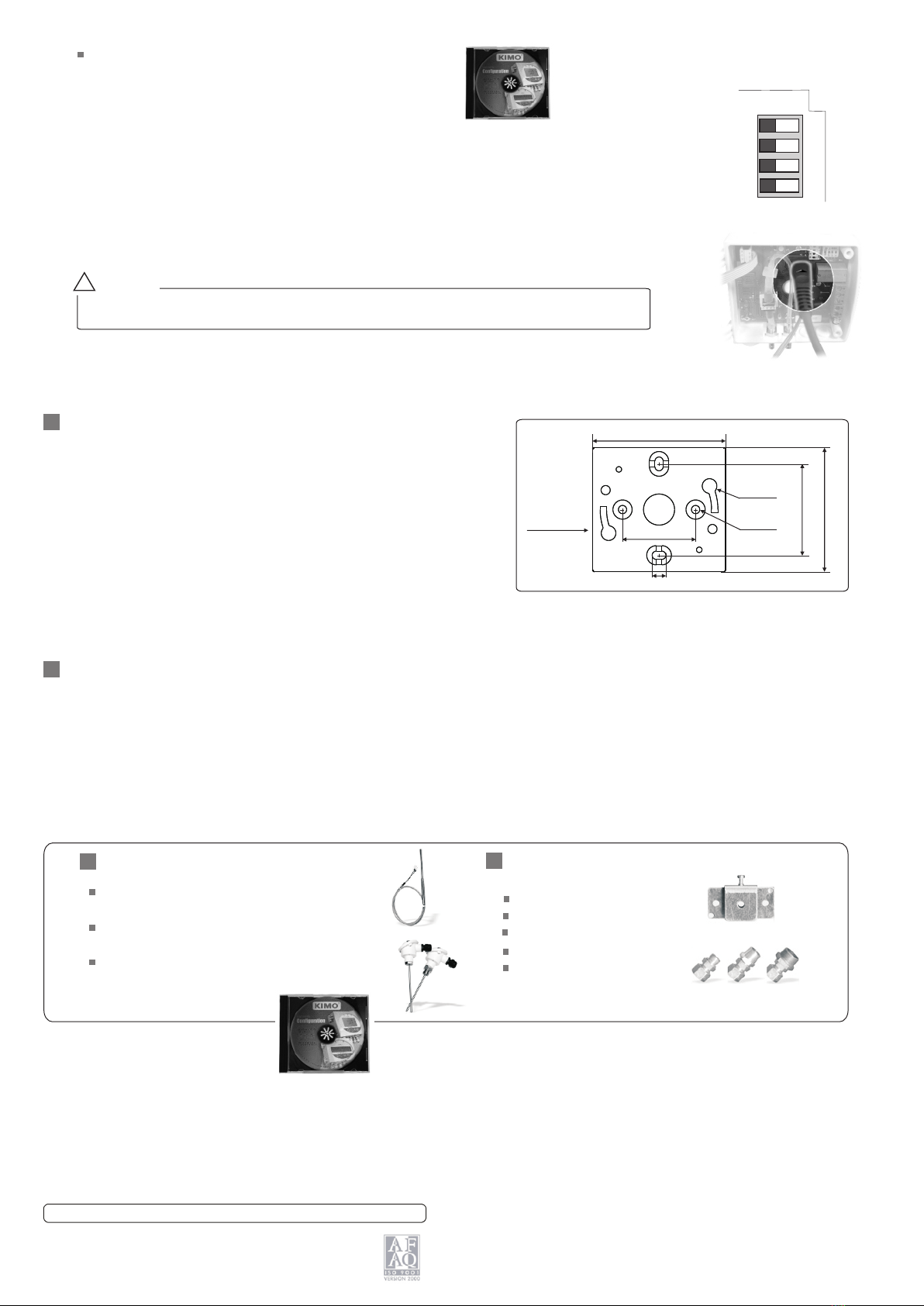
Dimensions ........................................see drawings beside
Protection............................................IP 65
Display.................................................5- digit LCD. Dimensions 50 x 15 mm
Height of the digits .............................10 mm
Cable grip ............................................for cables Ø 7mm maxi.
Weight..................................................145g (with display) - 110g (without display)
Technical Specifications
Output / power supply....active transmitter 0-10 V (power supply 24 Vac/Vdc ±10%), 3-4 wires
passive loop 4-20 mA(power supply. 18/30 Vdc), 2 wires
maximum load : 500 Ohms (4-20 mA)
minimum load : 1 K Ohms (0-10 V)
Consumption ....................................2 VA (0-10V) or max. 22 mA(4-20mA)
Electro-magnetical compatibility .......EN 61326
screw terminal block for cables Ø 1.5 mm² max
Communication to PC ...................... Kimo RS 232 cable
Working temperature (housing)..........0 to +50°C
Working temperature (probe) .............-20 to +80°C (duct mount probe)
according to the probe (Pt100 on terminal block)
Storage temperature ........................-10 to +70°C
Environment .....................................air and neutral gases
..........................................
..........................................
..........................................
Electrical connection .......................
VActive • 24 Vac/Vdc • 0-10V
A Passive • 18/30 Vdc • 4-20 mA
TG 100
duct mount
TG 100
Pt 100 on terminal block
(probe in option)
Dimensions of the housing
(with wall-mount plate)
Pt100 on terminal block
100 mm 42 mm
83 mm
Duct mount
100 mm 42 mm
83 mm
150 mm
Ø 13 mm
Working principle : Pt100 is a resistance with a positiv e
coefficient which varies according to the temperature. The higher the
temperature is, the more the value of the resistance increases.
Example : for 0°C 100 - for 100°C 138,5
e temperatur
*All the accuracies indicated in this technical datasheet were stated in laboratories conditions, and can be guaranted for
measurements carried out in the same conditions, or carried out with calibration compensation.
w
e
N
w
e
N
Technical Data Sheet
Pressure • Temperature • Humidity • Air Velocity • Airflow • Sound level

-
+
+
-
Vdc
IT
Power supply
18-30 Vcc
Vdc...........direct voltage
GND.........ground
b
Connection
Cable tubing
Power supply
terminal block
Output
terminal block
a
b
c
Electrical connection - as per norm NFC15-100
!
cCable grip : to insert the cable, it is required to
slightly cut the rubber.
Terminal
block
a
Connection
to PC
LCC 100
software
e
DIP switch
d
TG 100 - VOA, TG 100 - VNA • Output
active sensor
0-10 V
For the models
GND .................ground
Vdc T................direct voltage (temperature)
a
Output
Power supply
OR
Vac...........alternative voltage (phase)
Vac...........alternative voltage (neutral)
b
TG 100 - VOA, TG 100 - VNA, TG 100 - VOE, TG 100 - VNE •Output 0-10 V - active loop
4 wires
Regulator display
or PLC / BMS
passive type
--
++
GND
Vdc T
-
+
+
-
Power supply
terminal block
Output
terminal block
Vdc
GND
Power supply
24 Vdc
or Vac
Vac
Power supply
24 Vac
Class II
~
~~ ~
3 wires
!
or
+
GND
Vdc T
-
+
+
Power supply
terminal block
Output
terminal block
Vdc
GND
Power supply
24 Vdc
+
GND
Vdc T
Power supply
terminal block
Output
terminal block
Vac
GND
Power supply
24 Vac
~
Phase Neutral
TG 100 - AOA, TG 100 - ANA, TG 100 - AOE, TG 100 - ANE
• Output 4-20 mA - passive loop
For the models
For the models
2 wires
Regulator display
ou PLC / BMS
passive type
-
+
+
-
Vdc
IT
Regulator display
or PLC / BMS
active type
+
Iin
or
Pt100
1
2
2' 1
2
2'
Connection of the Pt100 probe
for the models
TG 100 - VOB, TG 100 - VNB, TG 100 - AOB, TG 100 - ANB
Terminal block
a
a
TG 100 - AOA, TG 100 - ANA
Output 4-20 mA - passive loop
For the models
Vdc...........direct voltage
IT..............direct current (temperature)
TG 100 - AOB, TG 100 - ANB
Output 4-20 mA - passive loop
For the models
TG 100 - VOB, TG 100 - VNB • Output 0-10 V - active sensor
For the models
Power supply
terminal block
Output
terminal block
a
b
DIP switch
d
Connection
to PC
LCC 100
software
e
Cable grip
c
f
2’ 2 1
Pt100
terminal block
f
Vdc...........direct voltage
GND.........ground
b
Power supply
OR
Vac...........alternative voltage (phase)
Vac...........alternative (neutral)
b
GND .................ground
Vdc T................direct voltage
(temperature).........................
a
Output
aVdc...........direct voltage
IT..............direct current (temperature)
f
2’ 2 1
Pt100
terminal block
4 wires
3 wires 3 wires
2 wires
2 wires
-
+
-
+
2
This connection must be made by a qualified technician. To make the connection, the transmitter must not be energized.
To make a 3-wire connection, before powering up the transmitter, please connect the
ground to the output of the input ground. See drawing below.

Configuration
To configure the transmitter, please unscrew the 2 screws from the housing,
and then open it.
!Caution !
Configuration by DIP switch
• Units setting
To set the measuring unit, please put the on-off switch 4 of
units, as shown beside.
• Measuring range setting
To set the measuring range, please
put the on-off switches 1, 2 and 3 of
the measuring range, as shown
beside.
DIP
switch
Electronic
board
d
Identification of
DIP switch on the board
DIP switch
}
Measuring range
setting
Units setting
1
2
3
4
On-off switch
Configurations
Combinations
0 to 50 °C -20 to 80 °C -50 to 50 °C 0 to 100 °C
1
2
3
4
1
2
3
4
1
2
3
4
1
2
3
4
Configurations °C °F
Combinations
1
2
3
4
1
2
3
4
0 to 200 °C
1
2
3
4
0 to 300 °C
1
2
3
4
0 to 400 °C
1
2
3
4
Measuring range
duct mount
Measuring range
Pt 100 on terminal block
3
To configure the transmitter, it must not be
energized. Then, you can make the settings
required, with the DIP switches (as shown on the
drawing beside). When the transmitter is
configured, you can power it up.
Please follow carefully the combinations beside with the
DIP switch.
If the combinations are wrong, the following message will
appear on the display of the transmitter “CONF ERROR”.
In that case, you will have to unplug the transmitter, place the
DIP switches correctly, and then power the transmitter up.
When the transmitter is powered up, it initializes and displays the digits and then its configuration including :
,
- the measuring range - the analog output.
1- The measuring range
The following message is displayed : . This is the low value of the measuring range, and its digit value : ex : .
The following message is displayed : . This is the high value of the measuring range and its digit value : ex : .
The arrow displayed (at the bottom or on the right of the screen) is relative to the unit of measurement : ex : from 0 to 400 °C.
2 - The analog output
If the analog output is in 4-20mA, then the following message will appear .
If the analog output is 0-10 V, then the following message will appear .
After the display of the configuration, the transmitter displays , which confirms that the initialization is finished and you can start the measurements.
0.0.0.0.0
L0
H.4 0 0. .
4 - 2 0 A. . . .
0. .0.- 0
Initialization the transmitter
It is possible to configure the measuring ranges, the units, the output of the transmitter (according to the model) either by DIP switch
and/or via software (connections and on drawing “connection)
ed

Ref. FT ang - TG 100 - 12/08 C - We reserve the right to modify the characteristics of our products without notice.
Please avoid any aggressive solvent.
Please protect the transmitter and its probes from any
cleaning product containing formol, that may be used
for cleaning rooms or ducts.
Maintenance
Mounting
A
A
ABS
plate
73 mm
68 mm
Ø 4,5 mm
40 mm
50 mm
Ø 8 mm
7 mm
Power supply class 2, input 230 Vac,
output 24 Vac, ref.KIAL-100A
Configuration LCC 100 software with RS
232 cable
Temperature probes Pt100 3 wires (for
model TG 100 on terminal block)
Options Accessories
Installation : mount the ABS plate on the wall (this plate is supplied
with the transmitter). Drilling : Ø 6 mm (with the screws and pins
supplied with the transmitter). Insert the transmitter on the plate (see
Aon the drawing beside) and rotate its housing in clockwise direction
until you hear a “click” which confirms that the transmitter is correctly
installed.
For the model with duct mount, an additional drilling of Ø14mm must
be done before mounting the ABS plate.
Connection tube
Connection fittings
Through-connections
Straight connections
Spherical coupling nut
The configuration of the parameters can be done either with the DIP switch, or via software (you
cannot combine both solutions).
!Caution !
Configuration via software
(with optional LCC100 software)
DIP switch
1
2
3
4
Example : for a transmitter with a range of -100 to +400°C, the minimum configurable range is 20°C.
For example, you can configure your transmitter with a range from -20 to +380°C, or from +300 to
+320°C...
• To access the configuration via software, you must first position the DIP switches as per the
following picture (shown beside), and then connect the cable to the transmitter (see beside and see
“Connection”).
• Please refer to the user manual of the LCC 100 to make the configuration.
An easy and friendly configuration with the software !
You can configure your own intermediary ranges.
www.kimo.fr Distributed by :
EXPORT DEPARTMENT
Tel : + 33. 1. 60. 06. 69. 25 - Fax : + 33. 1. 60. 06. 69. 29
export@kimo.fre-mail :
Table of contents
Other Kimo Transmitter manuals