ddtop UQZ User manual

1/ 14
WWW.DDTOP.COM
UQZ
MAGNETIC FLOAT LEVEL TRANSMITTER
Operation Manual
UQZ-DT-JS-1004-2018
(A)

2/ 14
WWW.DDTOP.COM
Preface
Thank you for choosing the products of Dandong Top Electronics Instrument (Group)Co.,Ltd.
This operation manual provides you with important information on installation, connection and
commissioning as well as on maintenance, troubleshooting and storage. Please read it carefully
before installation and commissioning and keep it as part of the product near the meter for easy
reading.
This manual can be downloaded by entering the version number at www.ddtop.com .
If the instructions are not followed, the protection provided by the meter may be destroyed.
Trademark, Copyright and Restriction Instructions
Dandong Top Electronics Instrument (Group) Co.,Ltd.®, Dandong Top Pump Co., Ltd.®, DDTOP®
are registered trademarks of the company.
The performance specifications of the meter are effective as of the date of publication and are
subject to change without notice. Dandong Top Electronics Instrument (Group)Co.,Ltd. reserves the
right to modify the products described in this manual at any time without prior notice.
Quality Assurance
Dandong Top Electronics Instrument (Group) Co.,Ltd. guarantees that all glass plate level gauge
have no defects in materials and manufacturing processes within one year from the date of delivery.
During the warranty period, if the product returns with quality problems and the claim is
determined by the manufacturer to be within the scope of warranty, Dandong Top Electronics
Instrument (Group) Co.,Ltd. is responsible for repair or replacement of the buyer (or owner) free of
charge.
Dandong Top Electronics Instrument (Group) Co.,Ltd. is not responsible for the costs caused by
improper use of equipment, labor claims, direct or subsequent damage and installation and use of
equipment. In addition to the special written warranty certificate for certain products of Dandong
Top Electronics Instrument (Group) Co.,Ltd., Dandong Top Electronics Instrument (Group) Co.,Ltd.
does not provide any express or implied warranty.
Quality
Dandong Top Electronics Instrument (Group) Co.,Ltd. has passed the ISO9001 quality system
certification. The whole process of product production is strictly in accordance with the scope of the
quality system, providing the strongest guarantee for product and service quality.

3/ 14
WWW.DDTOP.COM
CONTENTS
1 Safety Tips ....................................................................................................................................................................... 4
1.1 Explosion may result in death or serious injury.................................................................................4
1.2 Process leaks can cause serious injury or death................................................................................4
1.3 Failure to follow safe installation guidelines may result in death or serious injury................4
2 Product Manual............................................................................................................................................................. 4
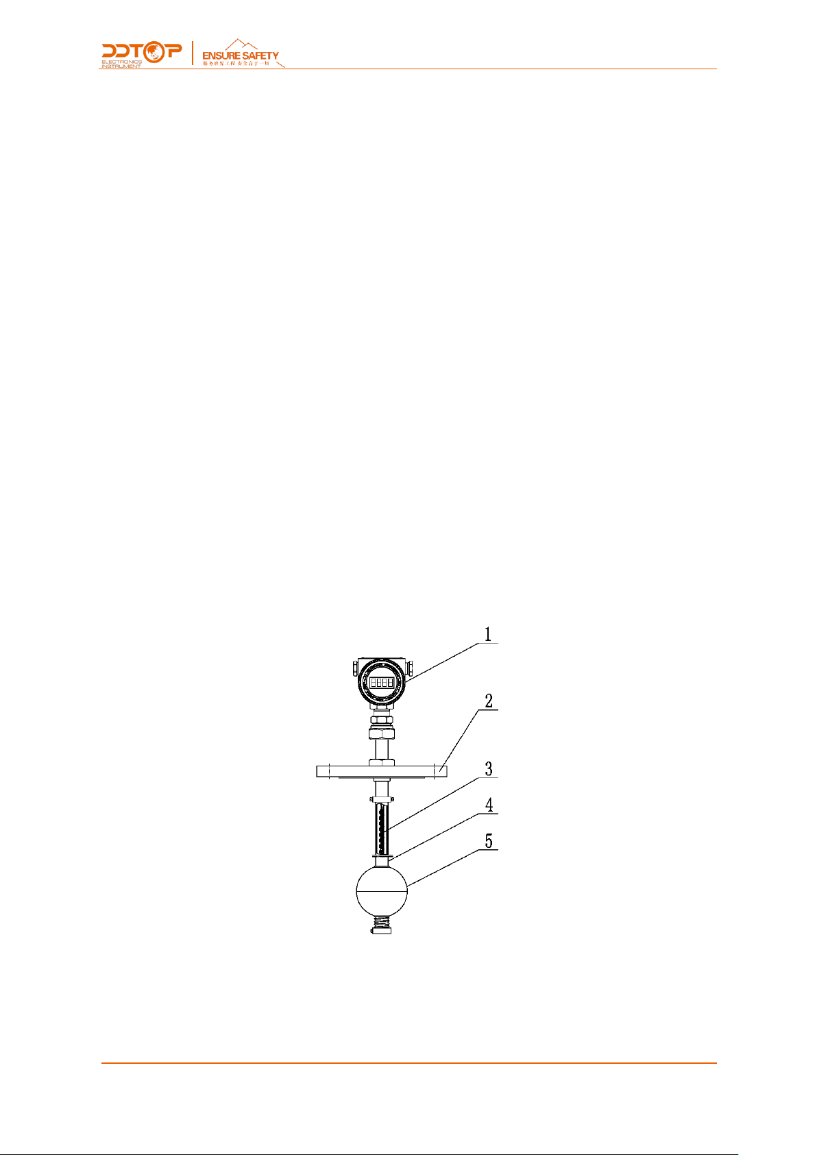
2.1 Product Basic Structure..............................................................................................................................4
2.2 Operating Principle .....................................................................................................................................5
2.3 Packing............................................................................................................................................................5
2.4 Hoisting and Transporting........................................................................................................................5
2.5 Storage............................................................................................................................................................5
3 Technical Characteristics............................................................................................................................................. 5
3.1 Product Features..........................................................................................................................................5
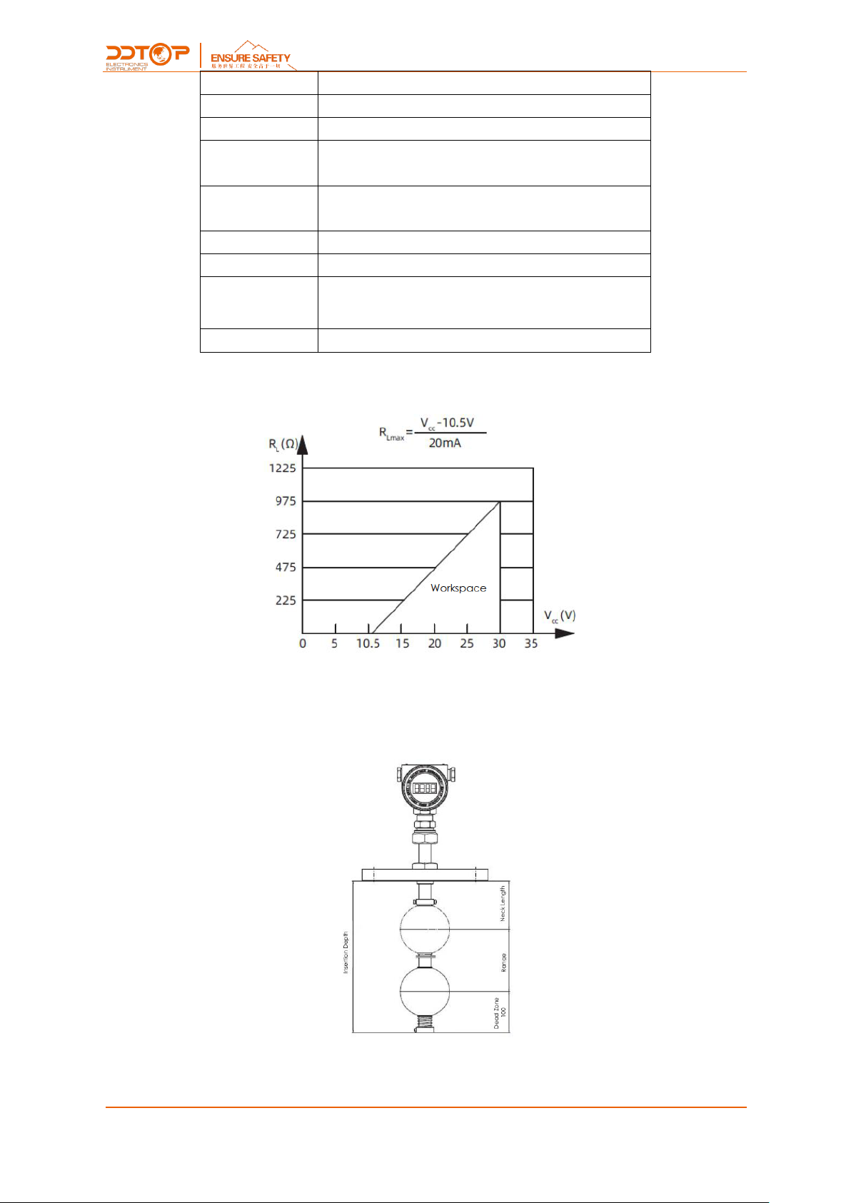
3.2 Main Parameter............................................................................................................................................5
4 Dimension Schematic.................................................................................................................................................. 6
5 Unpacking and Inspection ......................................................................................................................................... 7
5.1 Matters needing attention in unpacking and inspecting goods..................................................7
5.2 Check Content..............................................................................................................................................7
6 Installation....................................................................................................................................................................... 7
6.1 Installation Tool............................................................................................................................................7
6.2 Installation Technical Requirements......................................................................................................7
6.3 Installation Procedure ................................................................................................................................7
7 Debugging ...................................................................................................................................................................... 8
7.1 UQZ Magnetic Float Level Transmitter Debugging .........................................................................8
8 Precautions....................................................................................................................................................................13
9 Fault Analysis and Elimination ................................................................................................................................14
10 Disassembly................................................................................................................................................................14
10.1 Warning......................................................................................................................................................14
10.2 Waste Removal ........................................................................................................................................14
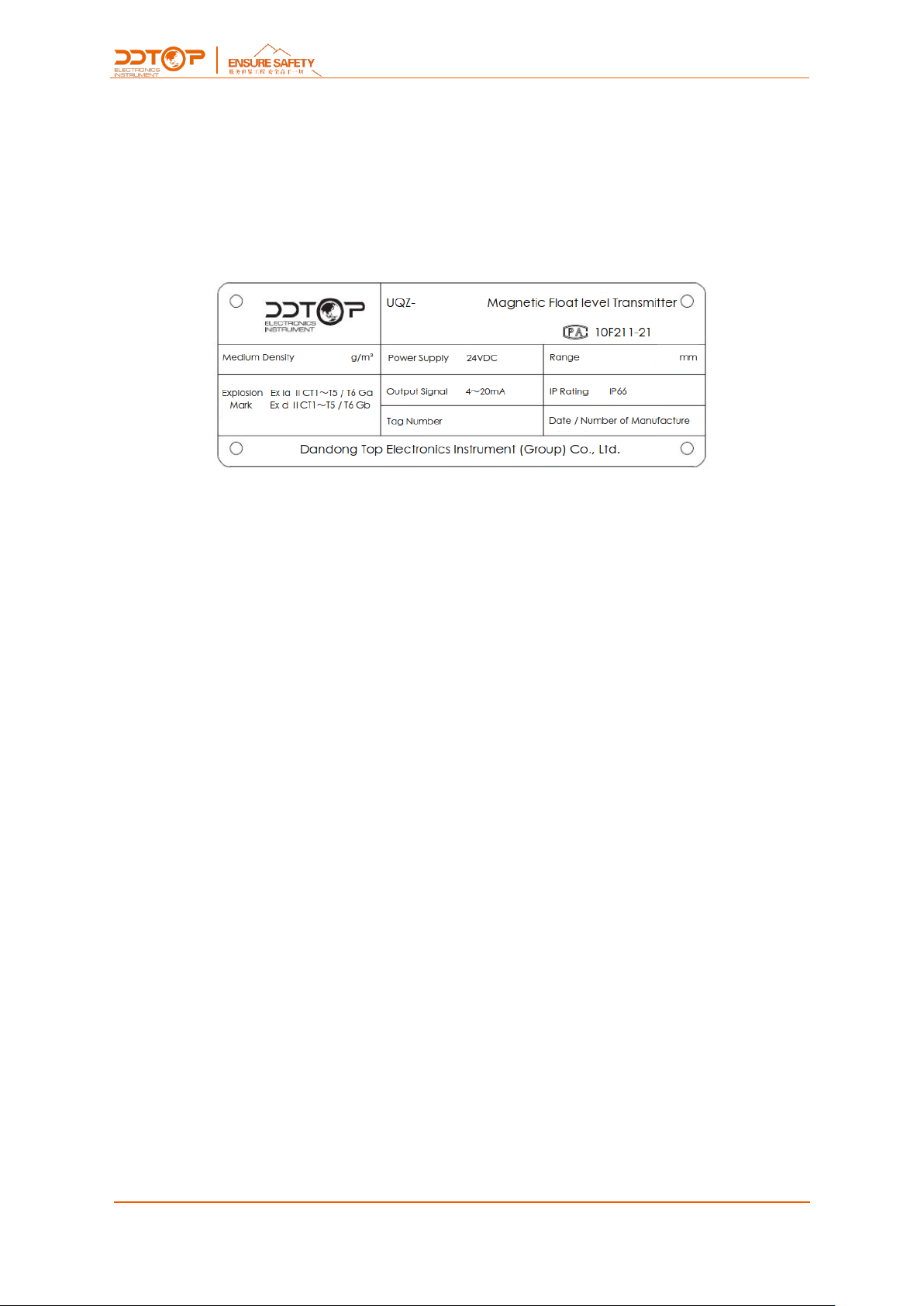
11 Product Certification................................................................................................................................................14

4/ 14
WWW.DDTOP.COM
1 Safety Tips
It is expressly prohibited to modify or change products for safety reasons,repair or replacement
only allows the use of accessories specified by the manufacturer.
1.1 Explosion may result in death or serious injury.
When installing equipment in an explosive atmosphere, be sure to follow applicable local, national,
international standards, codes, and procedures. Be sure to install the equipment in Intrinsically safe
or non-flammable site operating procedures.
1.2 Process leaks can cause serious injury or death.
Care should be taken to lift the transmitter. If the process seal is damaged, the medium may leak at
the joint.
1.3 Failure to follow safe installation guidelines may result in death or serious injury.
The operations described in this manual are performed by professionally trained and qualified
professionals or end-user specialized professionals to complete.
2 Product Manual
2.1 Product Basic Structure-Figure 1
Figure 1 Product Basic Structure
1. Meter head assembly, converter circuit and LCD screen
2. Flange, connection with equipment

5/ 14
WWW.DDTOP.COM
3. Reed switch-resistor components, sensor circuits
4. Housing, protective sensor circuit
5. Floating ball: measuring element
2.2 Operating Principle
UQZ magnetic float level transmitter with float and liquid level or boundary level change
synchronously, the magnetic steel inside the float makes the reed switch close or open, the
resistance value in the sensor circuit changes linearly, and then through the converter circuit in the
meter head assembly will be converted into 4~20mA standard DC signal, which will be displayed on
the LCD screen or output to the control room through the output terminal to realize the
long-distance transmission of the liquid level.
2.3 Packing
Please send the packaging waste to a special recycling agency.
2.4 Hoisting and Transporting
Please select qualified hoisting equipment and lifting straps, and pay attention to safety.
2.5 Storage
Storage temperature -20℃~40℃, storage humidity≤20%
3 Technical Characteristics
3.1 Product Features
3.1.1 UQZ magnetic Float Level Transmitter Explosion-proof certification as adopted, certification
mark:
Intrinsically safe Ex ia ⅡC T1~T5/T6 Ga
Explosion isolation Ex d ⅡC T1~T5/T6 Gb
3.1.2 Product implementation standards
GB/T 25153-2010 Magnetic Float Level Gauge for Chemical Pressure Vessels
JB/T 12957-2016 Magnetic Float Level Transmitter
3.2 Main Parameter
Range
0~6000mm(>6000mm It can be made beyond the range)
Flange standard
HG/T20592-2009、HG/T20615-2009 or on request
Nominal diameter
DN150、DN100
Nominal pressure
≤2.5MPa
Wetted material
304、316L or on request

6/ 14
WWW.DDTOP.COM
Power supply
24V DC
Output signal
4~20mA DC(with HART protocol)
Load characteristics
See load characteristics chart (Figure 2)
Ambient
temperature
-40℃~+80℃
Medium
temperature
-40℃~+120℃
Accuracy
±10mm
Power supply inlet
M20×1.5 (female thread) or on request
Explosion-proof
Intrinsic safety type Ex ia ⅡC T1~T5/T6 Ga
Explosion-proof type Ex d ⅡC T1~T5/T6 Gb
IP rating
IP66
Figure 2 Load Characteristics Chart
4 Dimension Schematic-Figure 3
If special dimensions are required when ordering, the actual dimensions shall prevail.
Figure 3

7/ 14
WWW.DDTOP.COM
5 Unpacking and Inspection
5.1 Matters needing attention in unpacking and inspecting goods
5.1.1 Check whether the product nameplate is consistent with the supply list information
-Figure 4.
Figure 4 Product Nameplate
5.1.2 Check the quantity of each part against the packing list and the material is correct.
5.2 Check Content
Check whether the appearance of the instrument is defective or damaged.
6 Installation
6.1 Installation Tool
Wrenches, flange gaskets and flange bolts for process connections
6.2 Installation Technical Requirements
6.2.1 Before installation, please observe the surface of the float ball carefully to make sure it is
smooth and smooth, and that there is no damage such as depression on the surface of the
magnetic float .
6.2.2 When installing the UQZ magnetic float level transmitter, the housing axis must be
perpendicular to the horizontal plane.
6.3 Installation Procedure-Figure 5

8/ 14
WWW.DDTOP.COM
Figure 5 Installation Procedure
6.3.1 When installing UQZ magnetic float level transmitter, as shown in Figure 5, the flange of the
level transmitter is connected to the flange of the process vessel, to ensure good contact between
the flange and the sealing gasket.
6.3.2 UQZ magnetic float level transmitter according to the following diagram to complete the
wiring - Figure 6
Figure 6 Wiring Diagram
7 Debugging
7.1 UQZ Magnetic Float Level Transmitter Debugging
This section describes how to configure the internal parameters using the 3 local keys (Enter ←←
←), (Up key "↑"), (Down key "↓") and the LCD display.
7.1.1 LCD Display Function Overview
Full screen information is shown in (Figure 7-1).The LCD LCD can display variables including current

9/ 14
WWW.DDTOP.COM
(Figure 7-2), percentage (Figure 7-3), and main variable (Figure 7-4), and can be set to display a
single variable, or the percentage and main variable can be set to cycle through the display, and the
valid bits of the decimal part can be set (0, 1, 2, 3, and 4 decimal places). If the percentage and main
variable are cycled, the LCD will display these two variables alternately with a period of 3 seconds.
Figure 7-1 LCD Full Screen Display Figure 7-2 Current Display
Figure 7-3 Percentage Display Figure 7-2 Main Variable Display
7.1.2 Description of LCD display symbols
①If you are in HART communication, the symbol in the right corner of the LCD screen flashes
.
②若处于开方输出,LCD 显示 。
③If the fixed output current is set, the LCD will display .
④If write protection is enabled, the LCD will display .
⑤The three "888" displays in the lower left corner of the LCD indicate the temperature of the
electronic module and the menu number for configuration.
7.1.3 Description of key functions
The LCD panel has a total of three buttons, these three buttons are, the Enter key "←┘", the Down
key "↓", and the Up key "↑".
●The "↑" and "↓" keys are used to indicate the increase or decrease of data bits and the shift of
the decimal point.
●The "←┘" key is used to enter the prompt data setting screen and data saving.

10 / 14
WWW.DDTOP.COM
7.1.4 Parameter Configuration Method Explanation
Long press "←┘" when the "888" character in the lower left corner shows 1~17, it means the
transmitter is in the field configuration mode of menu rotation, now you can enter initialization code,
modify parameters, meter calibration or migrate by pressing the key.
The data setting process utilizes.
The "←┘" key is used to select the digits and decimal points to be edited and the final confirmation
of the save.
(Blinking for selected status)
The "↑" key is used to blink the number digits incrementally from 0 to 9 and to move the decimal
point to the right.
The "↓" key is used to flash the number of digits in decreasing order from 9 to 0 and to move the
decimal point to the left.
The setting process is as follows.
1. Press and hold down the key '←' to enter the data configuration interface, the lower left corner
will show '01' and the data line will show '00005'. Press the '←┘' key again, the symbol bit will
blink, indicating that the symbol bit can be modified.
2.If you press '↑' or '↓' key again, you can switch between positive and negative sign of data.
3. If you press the '←┘' key again, the first digit starts blinking when the selection of the symbol is
finished, it means the symbol bit can be modified. The numbers cycle between 0 and 9.
4. Press the '←┘' key again, the first digit is finished and you can set the second to fifth digit in the
same way as the first one.
5. After setting the fifth digit, press '←┘' key again to set the decimal point. The decimal point
starts blinking at the same time, which means you can set the decimal point, press '↑' key or '↓'
key to switch the decimal point position to the right or left circularly.
6. After the decimal point is set, press '←┘' key, the up and down arrows on the left side will light
up, which means save the setting.
7. Press the '←┘' key again to set the data again.
7.1.5 Keycode Lookup Table
When the key is used for field configuration, the two "888" display bit characters in the lower left
corner of LCD indicate the current setting menu number, which is the setting function performed by
the current key. The correspondence is as follows.
The "888" display bit in the lower left corner
shows
Set variables
0 or blank
Normal display
1
Enter operation code (00911 initialize instrument)
2
Set units
3
Set LRV
4
Set URV

11 / 14
WWW.DDTOP.COM
5
Set damping time
8
Density (to be used)
9
Arbitrary point migration input compensation value, compensation
value = P actual - P pre-output
11
LRV calibration
12
URV calibration
17
View Sensor Values
Calibration of the instrument can be done as described in "7.1.4 Data Setting Method", with upper
and lower range limits and damping settings.
7.1.6 Unit Setting
The units that can be set are: m, cm, mm, feet, and inch.
①Press and hold the '←┘' to enter the configuration mode (the No. 1 menu will be displayed first,
and the up and down arrows on the left will be lit).
②Press the "↑" to switch the menu to No.2 and display the current unit symbol in the lower right
corner.
Unit Setting
③Press the '←┘' key again, the unit starts flashing units, now press the '↑' key or '↓' to switch to
the unit you want to set.
④Press "←┘" again, the unit is set and the up and down arrows on the left side are lit.
7.1.7 Range Setting
Set the lower range LRV
①Press and hold the '←┘' key to enter the configuration mode (the No. 1 menu will be displayed
first, and the up and down arrows on the left will be lit).
②Press the "↑" key to switch the menu to No.3, and the LCD will show the current LRV value.

12 / 14
WWW.DDTOP.COM
Range Setting
③Press "←┘" key again, the symbol starts flashing, now press "↑" key or "↓" key to switch to the
positive or negative sign you want to set.
④Press the "←┘" key again to finish setting and start setting the maximum range. At this time,
press the '↑' key or '↓' key to set the current blinking digit increment or decrement and press the "
←" key to confirm, and then set the other digits and decimal points in turn, when the left up and
down arrows are lit, the menu item is set complete.
Set the upper range URV
Switch the menu to No. 4 while the current URV value is displayed on the LCD, and repeat the steps
③and ④in 7.1.6 for setting.
7.1.8 Damping Setting
Switch the menu to No. 5 while the LCD shows the current damping value, and repeat the steps ③
and ④in 7.1.6 until the setting is complete.
7.1.9 Two-point Calibration
LRV Calibration
①First adjust the PV value to the zero position (the magnetic float toggles to the zero position).
②Switch the menu to 11 while the LCD displays the current calibration position value. Then repeat
7.1.6 ③and ④to enter the zero point value for zero position calibration.
③Press the "←┘" key until the left up and down arrows illuminate the zero position.
URV Calibration
①First, adjust the PV value to the full degree position (magnetic float toggle to full degree).
②Switch the menu to No. 12 while the LCD displays the current calibration position value, and
then repeat 7.1.6 in ③and ④to enter the fullness value for fullness position calibration.
③Press the "←┘" key until the up and down arrows on the left illuminate the fullness position to
complete the calibration.
7.1.10 Any point migration
The '9' menu enables any point migration function. The user can migrate the current PV value to

13 / 14
WWW.DDTOP.COM
any point in the range. (Enter compensation value) The setup process is as follows.
①Press and hold the '←' key to enter the configuration mode (the No. 1 menu will be displayed
first, and the up and down arrows on the left will be lit).
②Press the "↑" key to switch the menu to '9' and the LCD shows the current PV compensation
value.
③Press the '←┘' key again, the symbol starts flashing, now press the '↑' key or '↓' to switch to
the positive or negative sign you want to set.
④Press the "←┘" key again to complete the setting, and the highest setting parameter blinks. At
this time press "↑" or "↓" to increment or decrement the current blinking digit, press "←" to
confirm and start the next digit setting, and then set the other digits and decimal points.This menu
function setting is completed when the left up and down arrows are lit.
Method of calculating the compensation value.
Compensated value = PV actual - PV pre-output
Note: The key configuration process will not exit automatically, you need to exit the key
configuration manually. The method is to press the '↑' key or '↓' key continuously in the switch
menu state, the menu will increase or decrease, when the menu is greater than 17 or less than
1, exit the key configuration state and enter the normal output mode.
8 Precautions
8.1 The temperature of the medium must not exceed 120°C, otherwise the sensor circuit will be
damaged.
8.2 Confirm that the power supply is safe and reliable and that it is connected in accordance with
the correct positive and negative polarity.
8.3 The use of UQZ magnetic float level transmitter is not suitable for occasions with high vibration.
8.4 Media viscosity ≥10-4 (m2 / s), not suitable for use of UQZ magnetic float level transmitter.
8.5 UQZ magnetic float level transmitter should not work in a strong magnetic field environment.
8.6 Tighten the power cover of the display after debugging to prevent water and moisture in the
meter.

14 / 14
WWW.DDTOP.COM
9 Fault Analysis and Elimination
Fault Phenomenon
Reason
Exclusion Method
No display on LCD screen, no
remote transmission
1. The float doesn't float.
2. Unplugged
3. Damage to electronics in the circuit test
board
1. Determine density or replace float
2. Turn on the power.
3. Replacement of damaged electronics in the
circuit test board
Display on LCD screen, no
remote transmission
Detect board damage
Replace the damaged electronics on the test
board
No display on LCD screen,
remote transmission
Damaged or poorly contacted ammeter
Change the ammeter
10 Disassembly
10.1 Warning
Attention should be paid to hazardous process conditions, such as pressure inside the vessel, high
temperatures, corrosive or toxic medium, etc.
Refer to the instructions in section 6.3 Installation Operation to remove the parts in the reverse
order of operation.
10.2 Waste Removal
Waste disposal should be carried out in accordance with the current guidelines in each region.
11 Product Certification
Table of contents