Inkonova tilt User manual

TILT Assembly Manual
Code No.: MD03001-00-1107
1

TILT Assembly Manual
Code No.: MD03001-00-1107
2
Building the TILT drone
Process of building the TILT is common to all versions current versions: the parts may differ (it will be specified when 3DP and PRO
versions use different components) but assembly remains the same. Please follow the steps given below. You might find extra screws in
most steps than the ones strictly necessary OR very similar lengths than the ones stated in this manual but that should still be suitable.
NOTE: Please refer the Getting Started document for the detailed description of the part names and their functions.
Step 1
Insert the polymer
bearings on each arm
support part (4 pieces,
two left-hand and two
right-hand) and insert it
until it gets flushed on
the other side. Use a 9
or 10 mm drill bit or
similar to insert it as it
goes press fit.
PARTS
4x polymer bearings (large)
2x arms support RIGHT
2x arms support LEFT
HARDWARE
None

TILT Assembly Manual
Code No.: MD03001-00-1107
3
Step 2
Install both tensors, one
on a right-hand arm
support and the other
in a left-hand one. Do
not tighten them yet.
NOTE: you’ll find a
regular washer for M3
to use instead of the red
aluminium parts in the
picture
PARTS
Same as step 1
2x polymer bearings (small
ones)
HARDWARE
2x screw M3x30
2x lock nut M3
4x washer for M3
2x split washer for M3
2x 10mm Nylon cylinder

TILT Assembly Manual
Code No.: MD03001-00-1107
4
Step 3
Mount all four arm
supports with the
tensors on the base
plate. On each arm
support, use only the
inner screws now.
NOTE: pay attention to
the position of the
tensors. The base plate
has in its design a couple
of ‘arrows’ marking the
forward direction (in
picture top is front). In
that orientation the
tensors must both be on
the left.
PARTS
Same as step 2
1x base plate
4x 20 mm aluminum standoffs
HARDWARE
4x screw M3x20 (PRO version)
4x screw M3x25 (3DP version)

TILT Assembly Manual
Code No.: MD03001-00-1107
5
Step 4
Install the shafts with
the pulley in both front
and rear arms supports.
Do not tighten the
pulley set screws yet,
keep the pulleys
completely loose.
PARTS
Same as step 3
2x 8mm diametre shaft
2x pulley with 8mm bore *
HARDWARE
4x set screw M3 (long)

TILT Assembly Manual
Code No.: MD03001-00-1107
6
Step 5
Place the arm
connectors in the
shafts and tighten well
the screws.
PARTS
Same as step 4
4x arm connector
HARDWARE
4x screw M3x16
4x lock nut M3

TILT Assembly Manual
Code No.: MD03001-00-1107
7
Step 6
Mount the each motor
in a motor mount with
the M3x6 screws (4 on
each motor) and
thread lock
(medium/blue). Then
add the motor mount
clamps (the bottom
part of the motor
mount assembly) and
the carbon fiber tubes
inserting them until
the end of the mounts.
Do not tighten the
M3x20 screws yet,
keep them tight but
allowing the tube to
rotate
PARTS
4x motor mount
4x motor mount clamp
4x brushless motor
4x carbon fiber tube
HARDWARE
16x screw M3x6
8x screw M3x20 *
8x lock nut M3
* the mounts and tube have
extra bores that can be used
for positioning and even
keep them installed

TILT Assembly Manual
Code No.: MD03001-00-1107
8
Step 7
Mount the arms in
the arm connectors
and tighten the
screws.
PARTS
Same as steps 5 and 6
HARDWARE
4x screw M3x25
4x lock nut M3
TILT Assembly Manual
Code No.: MD03001-00-1107
9
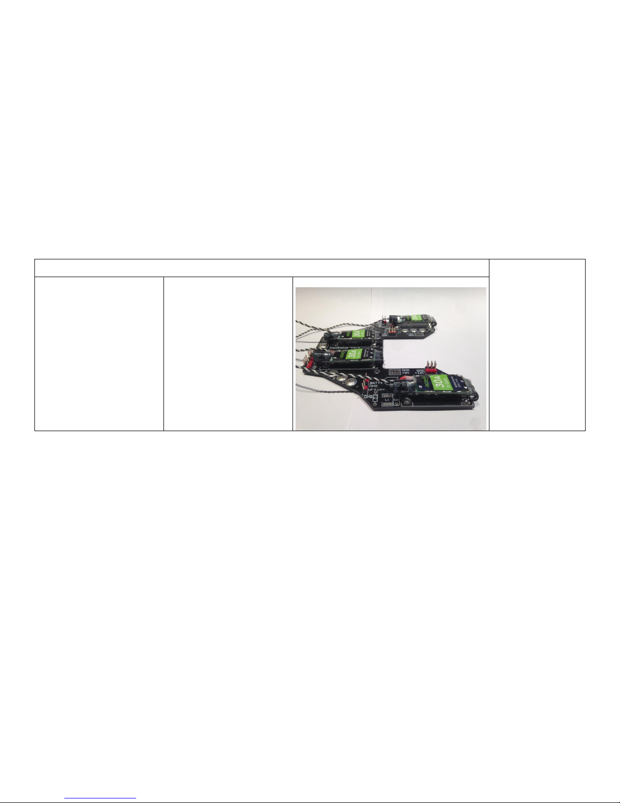
Step 8
If you have purchased
a PDB refer to the
PDB manual for
detailed description
on how to solder the
PDB components.
The picture shown
here is just orientative
of how it should look
like prior to mounting
the PDB to the frame
PARTS
Refer to the PDB manual
for detailed instructions
HARDWARE
Refer to the PDB manual
for detailed instructions
TILT Assembly Manual
Code No.: MD03001-00-1107
10
Step 9
Install the two Nylon
screws and nuts as
shown in the
pictures. The length
supplied is to be used
with landing legs. If
you do not want to
use landing legs you
can cut the Nylon
screws to a suitable
length. The nuts are
here important as
they serve as spacer
to avoid the exposed
bottom PDB pins to
touch the carbon
fiber base plate and
create dangerous
shorts. In the actual
design we do
recommend to use
Nylon screws if using
aluminium landing
legs.
PARTS
Same as step 8
HARDWARE
2x screw Nylon M3x12
2x nut Nylon M3

TILT Assembly Manual
Code No.: MD03001-00-1107
11
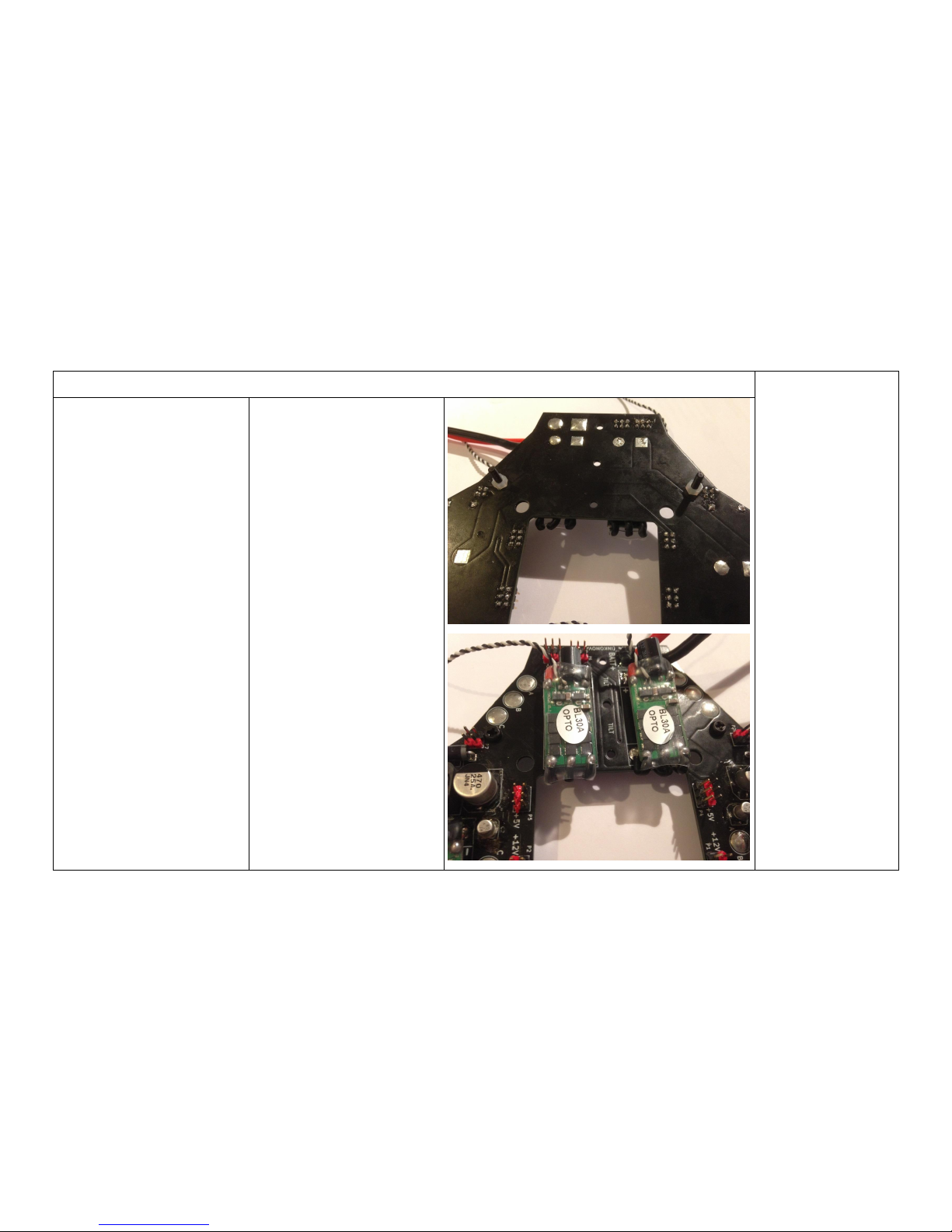
Step 10
Install the Nylon
screw and nut as
shown in the picture.
This screw will be
used to hold the PDB
and the nut as spacer
to avoid shorts. If not
using landing legs,
the screws in step 9
can also be installed
in this way.
PARTS
Same as step 7
HARDWARE
1x screw Nylon M3x12
1x nut Nylon M3

TILT Assembly Manual
Code No.: MD03001-00-1107
12
Step 11
Solder the pin headers
to the Naze flight
controller board as
shown in the pictures
with the black Naze32
board (headers
supplied). Cut the Nylon
screws to about 6 mm
long and install the
standoffs in the flight
controller.
If you want a low
profile headers setup,
you can use the red
Naze pictures as
example (rubber
dampeners not
included in the kit)
PARTS
1x Naze32 flight
controller board
HARDWARE
4x screw Nylon M3x12
(to be vut to about 6 mm
long)
4x standoff Nylon 10 mm
long Nylon
TILT Assembly Manual
Code No.: MD03001-00-1107
13
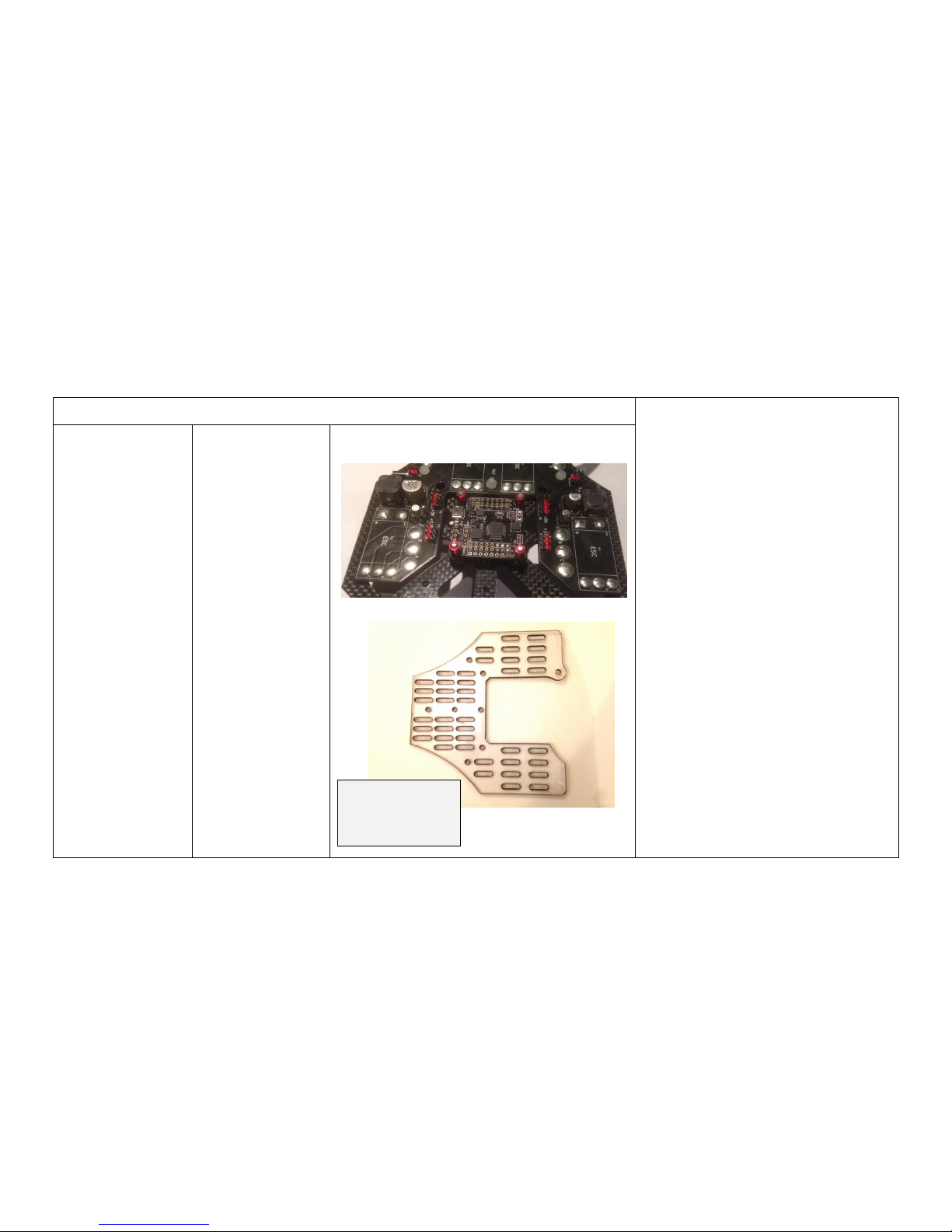
Step 12
Mount the flight controller with the
M3x6 on the base plate (the picture here
is just orientative) and the PDB or PDB
substitution with the Nylon nuts on the
already installed Nylon screws (for the
PDB substitution you do not need the
nylon nuts as separators as there is no
shortcircuit risk).
We recommend insulating the bottom
side of the PDB with electrical insulation
tape. It is not mandatory as the PDB and
solderings should not touch the frame
(CHECK!). We used Kapton (Polyimide)
tape to insulate the PDB from the carbon
fibre chassis.
NOTE: use tape with “low noise” glue
when possible. Some insulation tapes can
cause an increase in the noise in the
system. Using good quality tape with
suitable glue properties is good practice.
PARTS
Same as steps 9,
10 and 11
HARDWARE
4x screw M3x6
3x Nylon nuts
PDB substitution
(comes with all
frames)
TILT Assembly Manual
Code No.: MD03001-00-1107
14
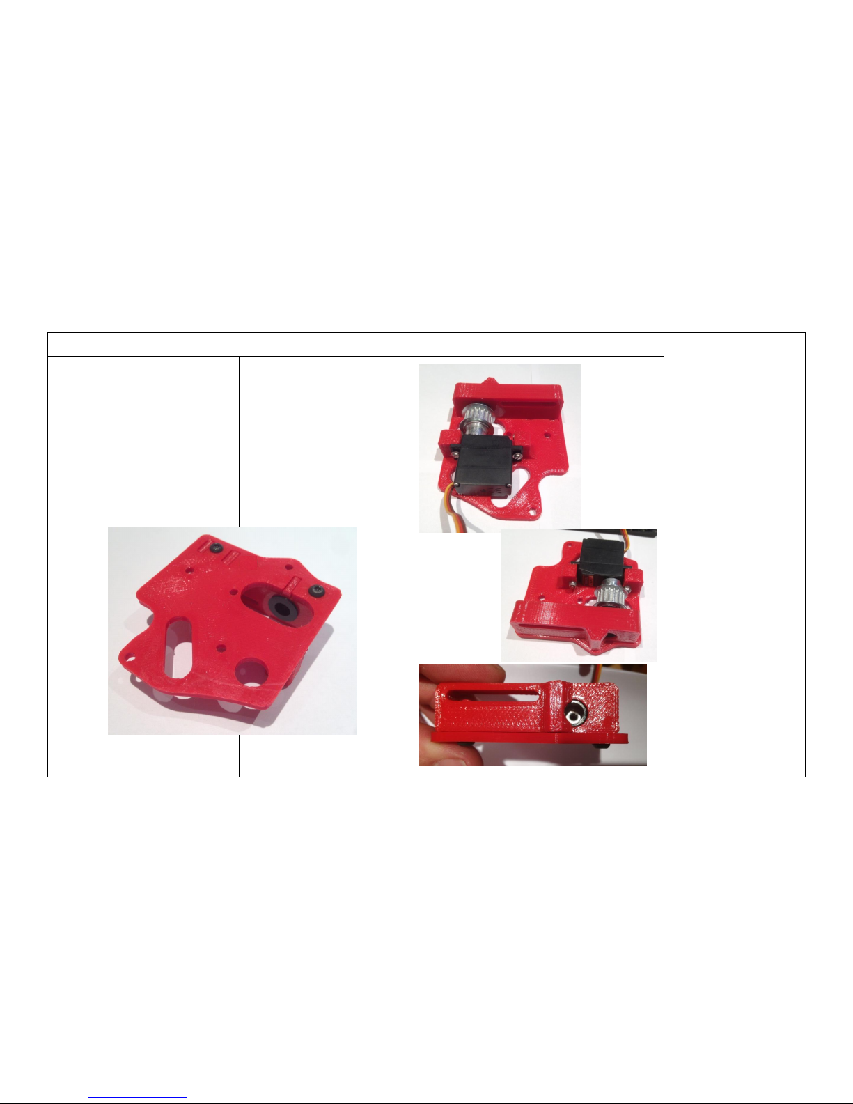
Step 13
Install the polymer
bearing in the IGUS
bearing housing. Then,
screw the servo bearing
housing into the servo
base with the M3x6
screws (keep the
middle bore empty).
Install the servo pulley
in the servo with the set
screws and then, the
servo in the base with
the M2 hardware.
Ensure the servo
pulley is aligned with
the polymer bearing.
Add the nylon cylinder
through the bearing and
screw the M3x20
screws to the pulley
through the Nylon
cylinder (use thread
lock here and do not
tighten excessively).
PARTS
Servo base
IGUS housing
Servo
1x polymer bearings (small)
1x Nylon cylinder 15 mm
HARDWARE
2x screw M3x6
1x screw M3x20
2x screw M2x12
2x washer M2
2x lock nut M2
2x set screw M3 (short)
TILT Assembly Manual
Code No.: MD03001-00-1107
15
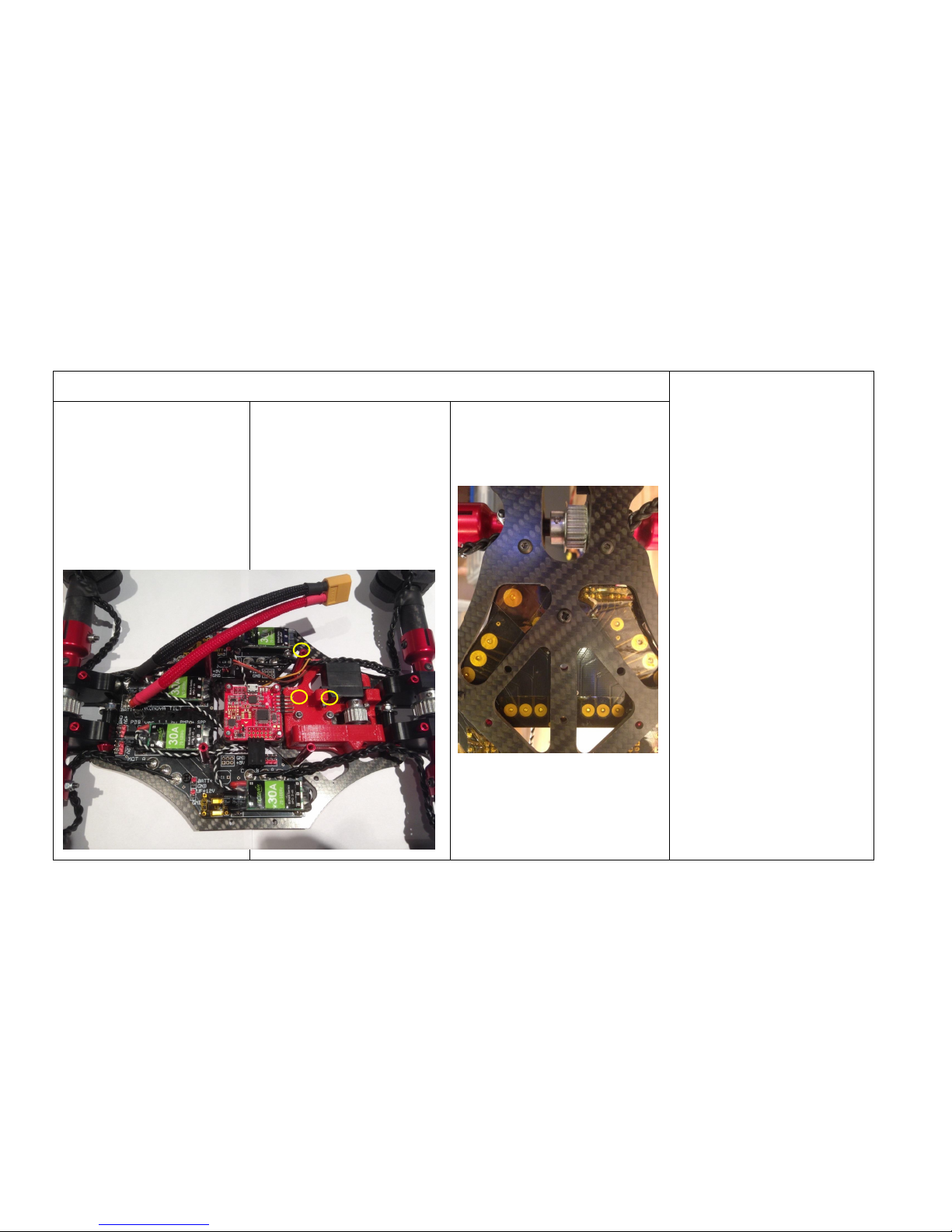
Step 14
Install the tilt servo assembly
to the base plate with the
M3x10 and M3 nuts (yellow
circles) and the four stand-offs,
also with M3x10.
PARTS
Same as step 12
Servo asembly
4x stand-offs 35 mm
HARDWARE
7x screw M3x10
3x lock nut M3
TILT Assembly Manual
Code No.: MD03001-00-1107
16
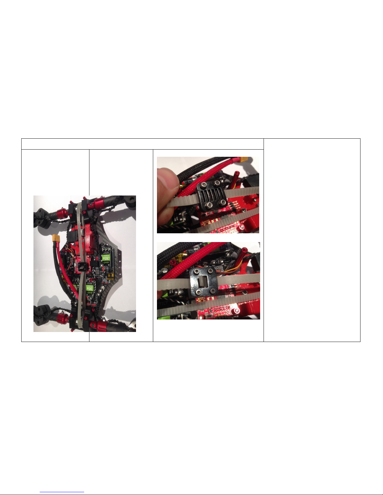
Step 15
Mark 490 mm span in the belt with a
marker leaving similar belt length on
both sides. Pass the open belt
through the pulleys as shown in the
picture.
Check the arms support tensors are
loose and on the bottom of their
travel range.
Install the belt clamp ‘tightening’ the
belt until the 490 mm marks are
being nearly covered by the clamp
parts. Ensure the belt teeth match the
clamp cavities.
PARTS
Same as step 14
Belt
Clamp parts A and B
HARDWARE
4x screw M2x10
4x lock nut M2
8x washer M2
TILT Assembly Manual
Code No.: MD03001-00-1107
17
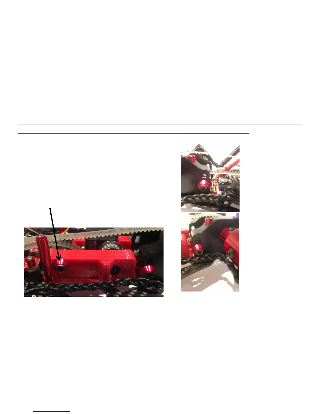
Step 16
Install the third belt
tensor in the servo
assembly with the
M3x25 screw and one
washer (instead of the
red aluminium part in
the picture: not
provided) and on the
other side of the 3D
printed red part, insert
first the split washer,
then the Nylon cylinder,
then the IGUS bearing,
the washer and finally
the M3 lock nut.
Lift the arm support
tensors to the middle
approx. and keep the
servo belt tensor loose
for now.
PARTS
Same as step 15
1x IGUS bearing (small)
1x Nylon cylinder 10 mm
HARDWARE
1x screw M3x25
1x lock nut M3
2x washer for M3
1x split washer for M3
Servo belt tensor

TILT Assembly Manual
Code No.: MD03001-00-1107
18
Step 17
Add the tip dummy
plates (acrylic) or
carbon fiber camera
plates in the front and
back at your
convenience: they are
placed in the gap below
the arm supports using
the two exterior screws.
PARTS
Same as step 16
Tip dummy plates or front
camera plate and/or rear tip
plate
HARDWARE
4x screw M3x20 (PRO version)
4x screw M3x25 (3DP version)

TILT Assembly Manual
Code No.: MD03001-00-1107
19
Step 18 (optional)
Add the gear platforms that you need
(two available). They just slide down
in the four central 35 mm stand-offs
and serve to place any gear you want
(receiver, video transmitter, etc).
PARTS
Same as step 17
HARDWARE
None

TILT Assembly Manual
Code No.: MD03001-00-1107
20
Step 19
Install the receiver and other gear.
PARTS
Same as step 18
HARDWARE
None or variable upon system


