Inmes IM-30 MM User manual
0504269
SAP:147/153
!!! For your safety In order to obtain
higher performance of your equipment !!!
Read the instructions manual carefully
OPERATIONS MANUAL
Http://www.inmes.com.br
IM-30 MM
RUS


INMES Industrial Ltda – IM-30 MM
2
CONGRATULATIONS!
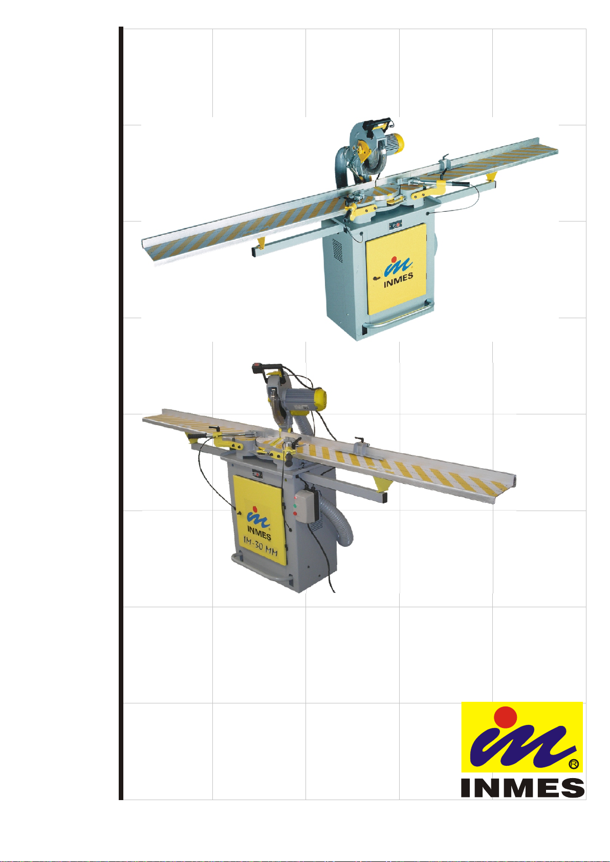
Congratulations for choosing the IM-30 MM and thanks for your confidence in INMES products.
This equipment was developed to satisfy safety and meet your needs for high performance. The
IM-30 MM was especially designed to make high-quality cuts in wood, profiles, however each material
requires the proper blade.
We developed this Owner’s Manual to help you install and use your machine correctly in order to obtain
the maximum benefits of economy and output.
Read the manual carefully and call us to answer any question you may have about your equipment and it’s
operation.
Visit our web site:
http://www.inmes-usa.com
Visit us and check out our wide range of products.

INMES Industrial Ltda – IM-30 MM
3
1 – SAFETY INSTRUCTIONS
For operator safety and durability of your equipment, the instruction must be carried out with great
care when installing and operating your machine, staying alert and learn how to use the IM-30 MM.
1.1 – Safety Signals
DANGER
If the safety instruction is not followed the operator will be seriously injured or killed.
WARNING
Means if the safety instruction is not followed the operator could be seriously injured or killed.
CAUTION
Safety instruction if not carried out with care, might injury the operator.
1.2 – Before using the machine
1.3 – Blade Requirement
The saw blade must proceed the following specifications:
•Extern diameter => 300 mm;
•Arbor diameter => 30 mm;
•Blades marked for 4 000 rpm or higher;
•Blades must be appropriated for each specific material (wood or plastic);
WARNING
!Read the owner’s manual before operating the equipment;
!Wear safety goggles,
!Keep the acrylic blade guard down;
!Keep hands out of the saw blade path;
!Turn off and wait for blade to stop, before adjusting;
!Before plugging in the machine to the electrical INMES Industrial recommends to use a thermo
magnetic circuit breaker on the electrical source as instructed in item 5.3 described in this
instructions manual;
!The manufacturer advice: you should make sure the circuit is properly grounded, using the
green and yellow wire for this purpose;
!The machine must be mounted on a flat surface in an appropriate work area, well lighted and
enough air;
!This machine only accept blade of 300mm
!In order to obtain high performance at work, make sure that you read the owner’s manual.
DANGER
!Do not use high speed steel sawblade because our sawblades work at a 1200rpm.

INMES Industrial Ltda – IM-30 MM
4
1.4 - When Installing the equipment
•The machine must be mounted on a flat surface in an appropriate work area, well lighted and enough air;
•Before switching on the machine, verify the frequency and voltage;
•The electrical installation should be made by an electrician, as well as questions or problems you may
have with your electric installation should be resolved by an electrician;
•Make sure you are using the correct voltage.
1.5 - Before Each Use
•Make sure switch is in OFF position before plugging in
•Make sure before operating that all parts and connections are tight;
•Keep the machine free from cutting residuals;
•Remove any existent foreign objects or tool between the fence and clamping;
•Verify blade spreader before start again;
•Always use the acrylic blade guard assembled;
1.6 – To reduce the risk of injury
•Never place your hand near the blade;
•Hold the profile firmly to the fence;
•Be careful when cutting small pieces,
the profile or small scrap may move
and break the blade or even damage
other parts;
•When cutting long profiles, its
necessary to use extension table (
have our authorized distributor called
), this accessory will let the profile
lay flat on the extension during
cutting operation;
•Let the blade get full speed before
cutting;
•Do not use blades which are not in a good shape, for instance, broken teeth, because they are out of
balance and will not make good cuts, as well as creating a hazard for the operator;
•Before starting the machine make sure that no objects have been left on the base;
•Soldered and unbalance blade must not be used;
•If any part is missing, bent or broken in any way, or electrical part does not work properly, turn the saw
off, unplug the saw and provide the proper maintenance;
•Never use your machine if you observe something which can cause an accident or damage the machine;
•Use only sharp blade;
CAUTION
•When cutting the profiles, the rabbet must be
facing the operator, as shown in figure 01 (F). Must
be avoid cuts as figure 01 (C) or else the saw blade
can pull the scrap piece into the machine, and that
way offering risk to the operator or damage to the
machine.
•In order to obtain a good finishing and safety when
cutting observe on top of the profile that you must
allow at least 3/8” (10mm) of wood between the
cut and the end of the stick as figure 01 (B).

INMES Industrial Ltda – IM-30 MM
5
•Keep the saw blade clean;
•Keep work area around clean, sawdust can
make the floor slippery;
•Make sure there is no debris between the
work piece and the fence;
•Never cut more than one work piece at a
time;
•Anytime the saw blade is removed for
replacement or maintenance; make sure
that the machine is unplugged from the
wall socket;
•After replacing make sure the blade is
properly tight;
•Keep visitors and children away when using;
Note: Always remember that careless fraction
of a second is enough to cause a severe injury
1.7 – Plan your cut
•Make sure the machine has enough cutting capacity to cut the profile you wish to;
•Use appropriate blade for cutting, depending on the type of material to be cut ( wood or plastic);
•When cutting the profiles with rabbet, the rabbet must be facing the operator as figure 01 (F).
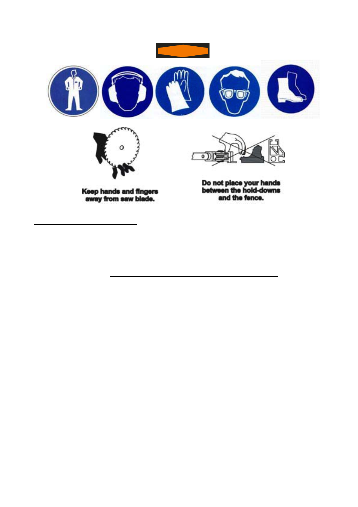
1.8 – Protection:
•Do not wear loose clothing, gloves or jewelry, neckties. They can caught you and draw you against the
moving parts;
•Tie back long hair;
•Wear ear plugs or muffs;
•Always wear safety goggles;
•For dusty operations, wear a dust mask along with safety goggles;
•Always remember that a fraction of a second can cause a serious injury.
Tip:
!When you have a large quantity of profiles to be cut, and you want to do this in a quick way, we advice the
operator to cut first one side, and then the other side. It means rapidity and will save your time, for it’s
not necessary to move the blade position several times.
3/8”
AB
Right
Wrong
CD
Rabbetfacing the operator
EF
profile
scrap piece
Figure 01
Wrong Right
Wrong Right
scrap piece
profile
INMES Industrial Ltda – IM-30 MM
6
WARNING
Before leaving the machine
•Turn the saw off and wait for all moving parts stop;
•Unplug the saw;
•Disconnect the circuit breaker from the power.
2– UNPACKING AND CHECKING CONTENTS
As soon as you receive the IM-30 MM Rotating Miter Saw, make sure that all parts are included.
The following parts are included:
Part or Assembly Quantity
Basic IM-30 MM Rotating Miter Saw 01
Mechanical Clamping System 01
RightTableExtension 01
LeftTableExtension 01
MouldingStop 01
Combination Wrench 24 x 27 mm 01
Phillips3/16”x4” 01
Wrench (for motor flange ) 01
Allen6mm 01
Warranty 01
INMES
RepairCenter 01
Owner’sManual 01
INMES Industrial Ltda – IM-30 MM
7
Optional Accessories:
♦Additional Right Table Extension ♦Work Stand
♦Additional Left Table Extension ♦Additional accessory for Fence
♦90º moulding stop or 45º moulding stop
3 –
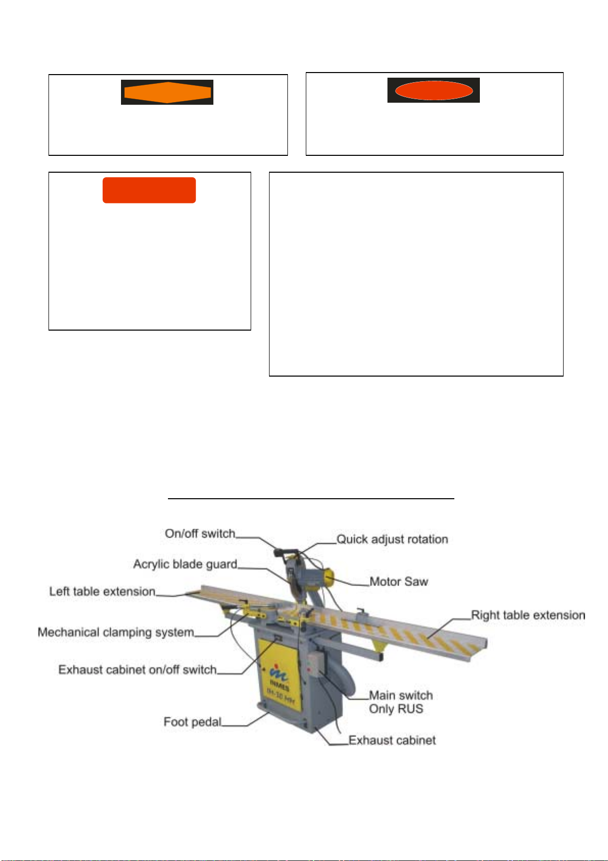
GETTING TO KNOW YOUR MITER SAW
WARNING
!If you are missing any part, do not assembly
the saw, contact our authorized distributor.
DANGER
!Do not plug the power cord into a power source
outlet when unpacking and assembling.
CAUTION
!To avoid back injury get help
whenever you have to lift the saw.
!Inmes developed a movable base for
IM-30; contact our distributor for
further information.
!Place the saw on a secure work
surface.
Important:
!Before installing the machine, make sure that you
have all the parts included.
!If you are missing any part, please do not hesitate to
contact our distributor.
!Always order by part number, use “Vista explodida”
you may find it at the list of parts located in the end
of the manual.
!This manual is extremely useful when ordering spare
parts, therefore keep it in a appropriate place,
should you have more than one equipment the same
model, identify the equipment writing the serial
number on its manual.

INMES Industrial Ltda – IM-30 MM
8
4 –
INSTALLING THE EXHAUST CABINET
To install the exhaust cabinet you must
fit the part (01) into the hose and then
attach this end of the hose over the
aluminum saw casting outlet using a
clamp 02 to tighten it. Once this
procedure is done attach the other side
of the hose over the dust collector
located inside the cabinet using a clamp
to tighten the hose.
As the saw dust is collected in a cloth
bag located inside the cabinet, we do
recommend to empty the bag at least
twice a week in order maintain the high
performance of your equipment.
In order to turn the dust collector on
and off you must press the switch 03
and then turn on the saw by pushing the
switch 04 fig. 02.
(Russia model)
1° - Attach the main switch 05 to the cabinet base 06 using the washers 07 and bolt 08 as shown in fig.
02.
2ª – Turn the main switch 05 fig.02.
3ª – Turn on the dust collector 03 fig. 02.
4ª – Turn on the saw 04 fig. 02.
1ª – Turn off the saw 04 fig. 02.
2ª – Turn off the dust collector 03 fig. 02.
3ª – Turn off the main switch 05 fig. 02.

INMES Industrial Ltda – IM-30 MM
9
5 –
IM-30 MM ELECTRICAL INSTALLATION
!To reduce electrical shocks or damage to the machine, unplug it from the power source before any
maintenance;
!If power cord is worn, cut or damage in any way, you must replace it right way;
!The electrical service must be performed by an specialist;
!Always install the machine in a dry floor, never expose the equipment in rain;
!Never place your hand or finger on the terminals of plug when installing or removing the plug to or from
the outlet;
!Overloading can occur if the operator start and stop many times in a short time, also the use of
improper or dull saw blades are used;
!Before plugging in the machine to the electrical INMES Industrial recommends to use a thermo
magnetic circuit breaker on the electrical source as instructed in item 5.3 described in this instructions
manual.
When using the machine for the first time, the operator must check out if the direction rotation of the
motor is right, otherwise he (she) must invert it.
•To invert the direction rotation in three phased machines, its necessary the inversion the two of the
three wire from power source, changing one for another. This proceed must be done by a specialist.
•To invert the direction rotation in single phased machines, you must change the wires position 5 and 8
(change one for another), inside the connection box. This proceed must be done by a specialist.
5.1 - Motor specifications for IM-30 MM
Induction motor three phase or single phase.
Available in: Consumed Power kw/h: Amps:
115 V Single Phase 1,27 kw/h 11,00 A
208-230 Single Phase 1,22 kw/h 5,55 A
Rotation 3400rpm
Power 1 hp
Frequency 60Hz
50Hz
Bearing
Front 6204 DDU ARZ S1
Back 6201 ZZ ARZ S1
WARNING
!Read the manual and the safety instruction carefully before connecting the plug to the power source.
!Make sure that all the screws are tight before installing the machine.

INMES Industrial Ltda – IM-30 MM
10
5.2 - Motor Specification for Exhaust Cabinet
Motor Induction three phase or single phase.
Available in: Consumed Power kw/h: 50Hz - 60Hz Amps: 50Hz - 60Hz
115 V Single phase 1,20 kw/h 10,40 A
208-230V Single Phase 0,80kw/h - 1,12 kw/h 3,64 A - 5,10 A
Rotation: 3535 rpm
Power: 0,75 hp
Frequency: 60Hz
50Hz
5.3 - Chart with specification for thermo magnetic circuit breaker
Inmes Industrial recommends installing a thermo magnetic circuit breaker on the electrical source,
preferably IEC Curve C standard (For inductive equipments) before connecting the machine to the electrical
source and make sure the circuit is properly grounded using the green/yellow wires for this purpose. This
service must be performed by a qualified staff.
In order to select an appropriate circuit breaker for your equipment use the chart below:
Tension Frequency Nominal current for motor Recommended circuit breaker
110V Single phase 60Hz 11A Bipolar 16A
220V Single phase 60Hz 5,55A Bipolar 10A
For the cabinet base with dust collector motor is also recommended to use a thermo magnetic circuit
breaker on the electrical source, preferably IEC Curve C standard (For inductive equipments) before
connecting the machine to the electrical source and make sure the circuit is properly grounded using the
green/yellow for this purpose. This service must be performed by a qualified staff.
In order to select an appropriate circuit breaker for the cabinet base use the chart below:
Tension Frequency Nominal current for motor Recommended circuit breaker
110V Single phase 60Hz 10,4A Bipolar 16A
220V Single phase 60Hz 5,1A Bipolar 10A
INMES Industrial Ltda – IM-30 MM
11
6 - INSTALLING AND MANTAINING THE SAW BLADE
Tools needed:
01- 24x27 wrench (supplied with machine)
02- 27 wrench (supplied with machine)
03- 3/16”x4" Phillips (supplied with machine)
You must follow the following steps:
Wear leather gloves when replacing or maintaining the blade.
Remember: Whenever the operator remove the blade for replacement or sharpening, its extremely important
to unplug the power cord from power source.
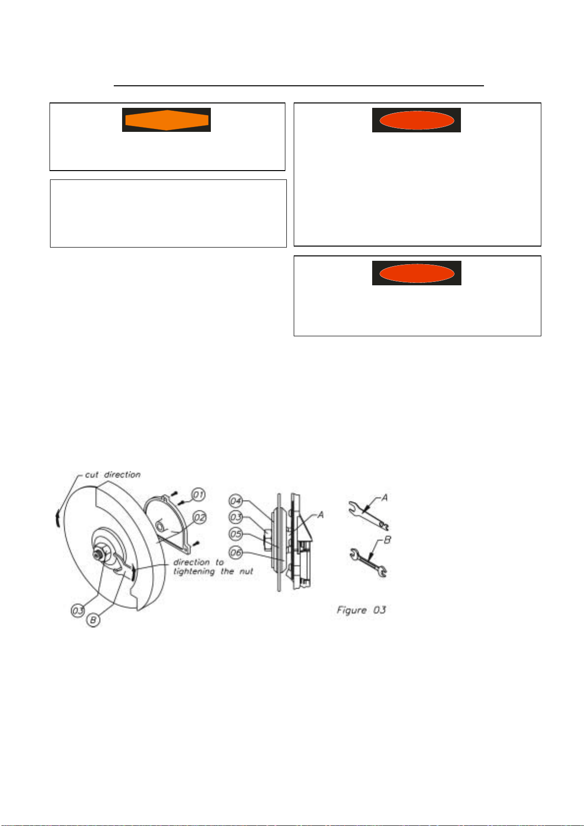
Once this is done proceed as shown as figure 03, following these steps:
1) Remove the three bolts
from the yellow plastic
flange, figure 03 (01);
2) Remove the yellow
plastic flange and the
acrylic blade guard
figure 03 (02);
3) Insert wrench 1 in the
region A as shown in
figure 03 (06);
4) Then Using wrench B
turn the blade nut
clockwise, loosen the nut, as shown figure 03 (03);
5) Rotate the wrench B down;
6) Rotate the wrench A up;
7) Remove the nut figure 03 (03);
8) Take the flange off figure 03 (04);
9) You are finally ready to remove the blade, figure 03 (05);
Important
Each material that you wish to cut (wood, plastic or
aluminum) requires a specific saw blade.
WARNING
!Use only blades of 300mm diameter.
DANGER
!The manufacturer advice do not use either
cracked or welded saw blade.
!Make sure all safety protection are correctly
installed.
!After changing or maintaining the blade,
make sure it is well tightened before
starting the machine.
DANGER
!Do not use high speed steel sawblade
because our sawblades work at a 1200rpm.

INMES Industrial Ltda – IM-30 MM
12
To replace the blade you must follow these steps:
When installing a blade, make sure the blade is clean and free of any protective coating;
When replacing the blade pay attention to the direction of the blade’s teeth.
Once you have checked all these points, then you will be able to replace the blade, following the respecting
steps:
1) Blade;
2) Flange, figure 03 (04);
3) Nut, figure 03 (04) manually tight to the end;
4) Insert wrench A in the region A, figure 03 (06);
5) Then using wrench B turn the blades nut counter clockwise, figure 03 (03);
6) Make sure the blade is well tight;
7) Fit the acrylic blade guard item 02, around the blade and right after that fix the yellow plastic flange
with three screws by a Phillips key;
8) Make sure the flanges are clean and properly arranged;
9) Lower the blade into the table slot and verify for any contact with the base;
10) If the blade contacts table, verify all the procedure that you have done, if you still have problem to
adjust your machine contact authorized service.
7. MOUNTING THE IM-30 SPRING
Before beginning working with your IM-30 Plus Rotating Miter
Saw, its necessary to install the spring, which it is already pre-
assembled on the machine.
To mount the spring, remove the bolt fig. 04 (01)
using Allen key 6mm that comes with the machine. Lift the top as
far as possible, using the handle, place the spring in the direction
of the arrow, until you are able to replace bolt in its original hole.
8. OPERATING YOUR IM-30 MM ROTATING MITER SAW
WARNING
!As soon as you have done, turn off the saw
and unplug the cord power from the out let.
CAUTION
!Use only saw blades specifically
recommended for wood, plastic, or
aluminum, according to the material you
want to cut.
INMES Industrial Ltda – IM-30 MM
13
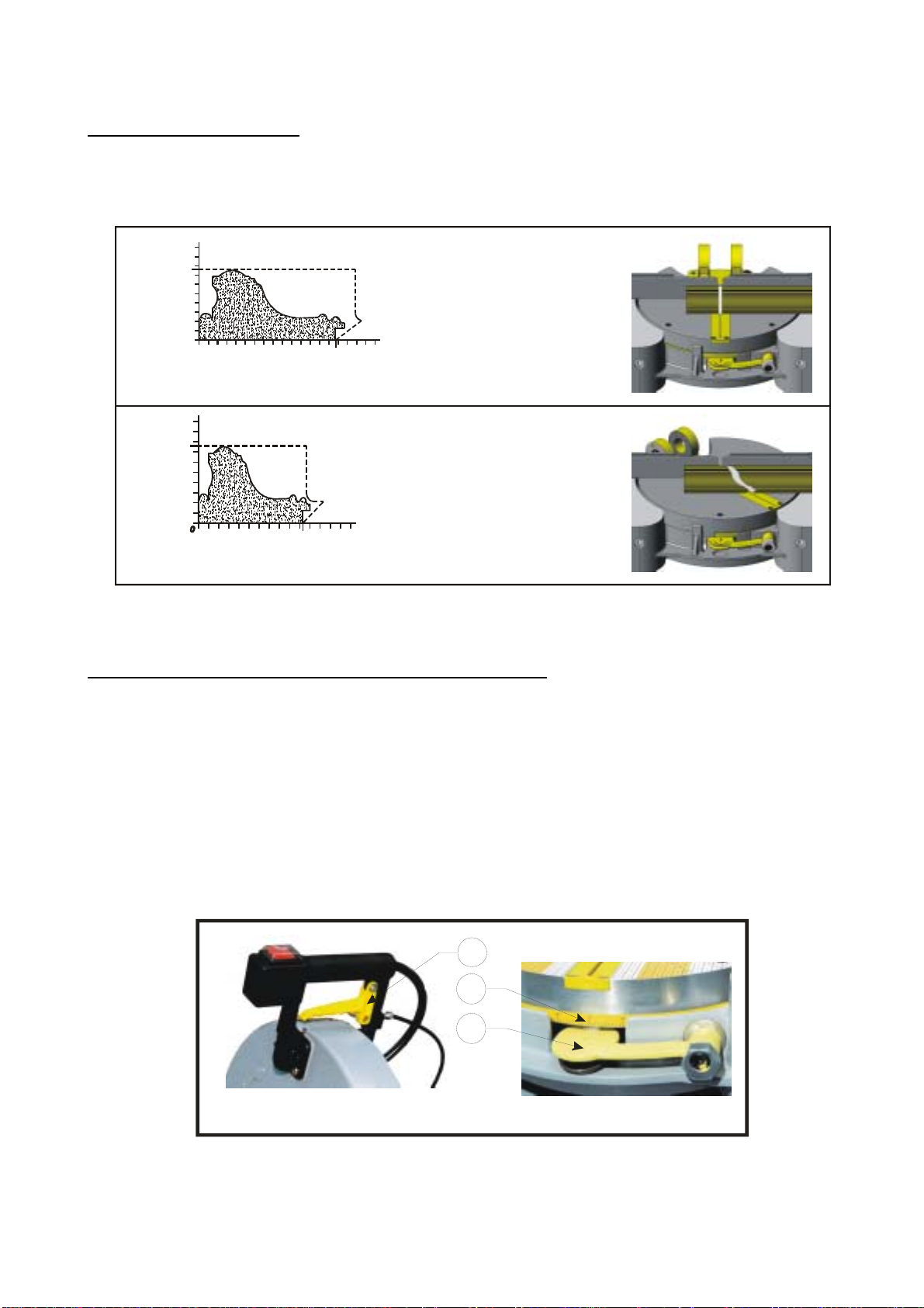
8.1 – Cutting Capacity
This machine has been designed for cutting profiles related in the following drawing below, according to
the respective cutting angles.
8.2 - Choosing the right angle you wish to cut
The IM-30 MM has a quick adjust rotation feature with precision lock position for the most used angles
(45° - 30° - 22,5° - 15° -10° ), and respectively for square and rectangles 6-8-12 and 18 sided frames, and
manual adjust for the other angles.
There are two ways you can adjust the cutting angle.
First:
The operator may use the “quick adjust rotation” feature, which is operated by squeezing the part that
looks like a bicycle brake in the middle the saw handle (next to the On/Off switch) in order to rotate the table.
When the desired angle of position has been reached, just released it to engage again.
02
03
Figure 05
01
Cut
Rotating Table 0°
Cut
Rotating Table 45°
100mm
4”
74mm
2 7/8”
(H - Height)
0
50mm
2”
100mm
4”
147mm
5 3/4”
190mm
7 1/2”
(L - length)
(H - Height)
(L - length)
100mm
4”
50mm
2”
150mm
5 7/8”
74mm
2 7/8”
102mm
4”

INMES Industrial Ltda – IM-30 MM
14
Second:
The operator may press down on the yellow lock disc on the front of the machine to disengage it,
then rotate the saw table until it reaches the position desired, then engage the lock again by releasing
the disk, taking care to have the position properly aligned, so as not to damage the lock pin.
It is possible to obtain the manual adjustment, as before press down on the yellow disk to
disengage the lock, rotate the saw to the angle desired, and then release the yellow disk, then tighten the
screw on top of the fence with your 5mm Allen wrench, which locks the rotating table in place.
Depending on type of frame to be made, follow the table below:
Side
s
Angl
e
04 45°
06 30°
08 22,50°
12 15°
18 10°
8.3 – Operating mechanical clamping system
1. Choose the profile you wish to cut (01);
2. Release the handle (02);
3. Step on the foot pedal (05) all the way
down, and keep it pressed;
4. Adjust the clamping system (03) in the
way of the arrow “A” in order to fit the
profile;
5. Place the profile between the fence
and the clamping;
6. Tight the handle (02);
7. Release the foot pedal (05);
8. Make sure to obtain a space of about
3/8” (10mm) between the clamping and
the profile before releasing the foot
pedal;
9. Observe that when stepping on the foot pedal (05) the clamping (04) moves in the way of arrow
“B” and “C”;
10. The clamping clamps the profiles in the way of arrow “D”
WARNING
!Before cutting, observe the clamping (04) fig (06); if it’s clamping the profile in the
correct way, otherwise it’s possibly to release during cutting, damaging the machine, or
even hurting the operator.
01
02
03
A
A
B
C

INMES Industrial Ltda – IM-30 MM
15
9 –
MAINTENANCE
9.1 - Alignment
To check the blades’ alignment, its required 24 x 27 mm wrench, combination square, 6mm Allen wrench.
Correction of the cutting angle
In case the angles are note true, you may start with the saw blade in the 0º position, to adjust the
calibration you must use a precision square to guarantee a perfect alignment of the blade. When you have
this tool (precision square) in hand, lower the blade, and place the back of the square placed against the
fence fig. (09), and the side of the square next to the blade.
After doing this operation, in case the angles are not true, you will notice a very small slot
between the square and the blade.
Correction of the cutting angle
Figure 09
04
01
02
03
Then use your 06mm Allen, loosen the screw figure 09 (03) then use your 24mm wrench and slowly turn
the adjustment screw fig 09 (02) to the left or right, until adjust the angle 90° between the saw blade and the
fence of the machine.
After adjusting the angle between the blade and the fence, you must tight the screw again, figure 09
(03), using your Allen 06mm, holding the adjustable screw, figure 09 (02), with your 24mm wrench, make sure
the adjustable screw do not move when tightening.
In order to have a perfect adjustment, you may cut 04 pieces and then make the joining.
9.2 Lubrication
!All the motor bearing in this equipment are lubricated with enough amount of high grade lubricant
for the life of the unit under normal operation conditions, therefore, no further lubrication is
required;
!To each eighty (80 hours) working hours it’s necessary to lubricate the yellow quick-adjust cable with
dust-graphite;
!It’s not required any other type of lubrication for the life of your IM-30 Plus.
Important
!To avoid damage to your
equipment, use only original parts.
WARNING
!For operator safety always turn the saw off and remove
the plug from the power source outlet before cleaning or
lubricating your equipment. If these instructions are not
followed the operator may be injured.

INMES Industrial Ltda – IM-30 MM
16
10 –
TROUBLESHOOTING
Problem Probable cause Suggested Solution
Motor does not work
Main feed cable not connected Connect the main feed cabl
e
Circuit breaker off Have circuit breaker checked
ON/OFF switch button damaged Get authorized servic
e
Defective contactor (three phase) Get authorized servic
e
Motor burned Get authorized servic
e
Motor rotate to the
wrong side Electric installation Invert the direction of the motor rotation
Motor does not
work fine during
cutting
Saw blade not sharpen Have it sharpen
Excessive cutting speed Lower cutting speed
Model of the saw blade Use blades with less teeth
Use anti-kickback blad
e
Frequent
disconnection of the
circuit breaker
Motor over-loaded Descent the blade slowly
Have the motor bearing checked
Undersized circuit breake
r
Install a circuit breaker with proper amp.
High level of noise Motor bearing damag
e
Get authorized servic
e
Motor problem Get authorized servic
e
Rough cuts
Saw blade not sharpen Have it sharpen
Awkward blad
e
Replace the blad
e
Blade incorrectly mounted Mount the blade correctly
Blade missing teeth Replace the blad
e
Motor bearing damag
e
Get authorized servic
e
Excessive cutting speed Lower cutting speed
Angle of cut not
accurate
Moulding fence misalignmen
t
Get authorized servic
e
Saw blade misalignmen
t
Make the alignmen
t
Awkward profil
e
Try another cut with a straight profil
e
Profile moves during cutting Secure the profile in place before cutting
Saw blade not sharpen Have it sharpen
Debris between the profile and moulding fenc
e
Clean it up
Hard to pull
Back Mains spring is broken Replace the spring
Hex nut from pivot shaft is too tigh
t
Release th
e
nut slowly
WARNING
!For your own protection, always switch “Off” and remove plug from power source outlet before
troubleshooting.

INMES Industrial Ltda – IM-30 MM
17
11 – PART LIST FOR IM-30 MM ROTATING MITER SAW
COD
E
DESCRIPTIO
N
COD
E
DESCRIPTIO
N
030202
2
Saw blade shaft
n
u
t
040802
5
Allen screw m8x16m
m
030600
3
Internal flange I
M
-
3
0
040802
6
Allen screw m8x20m
m
030600
4
External flange I
M
-
3
0
040802
7
Allen screw m8x25m
m
030600
6
Saw assembly support hin
g
040802
9
Allen
s
crew m8x35m
m
030600
7
Saw assembly shaft
040806
6
Hex nut m
5
030600
8
Table lock screw nylon ti
p
040808
1
3/16” washe
r
030601
2
Insert for 45° table positio
n
040809
1
Allen screw m5x16m
m
030601
5
Q
uic
k
-
turn handl
e
040813
2
Grease Jet M
6
030601
6
Table lock scre
w
040814
3
Allen screw m5x10m
m
030601
8
Rotating table
I
M
-
3
0
040816
4
Phillips screw MQP 4x08m
m
030602
2
Lever pi
n
040816
6
Phillips screw MQP 5x16m
m
030602
3
Acrylic blade guard leve
r
040817
3
Sel
f
-
locking nut
030602
9
Rotating table lock shap
e
040817
7
Hex nu
t
030603
3
Teflon dis
k
040817
8
Hex bol
t
030603
4
Support for acrylic blade guar mechanis
m
040817
9
Hex nu
t
030603
5
Blade guar mechanism sheath
040818
1
Rotating table cable scre
w
030603
7
Q
uick turn handle pi
n
040818
3
Rotating table cabl
e
030603
9
Cable regulator screw
040818
4
Phillips screw MQP 5x16m
m
030605
3
Acrylic blade guard suppor
t
040819
1
Phillips screw MQP 4x12m
m
030605
6
Electric cabl
e
–
main feed/single phase 1cv
040820
0
Washer
030606
5
Electric cable main feed / three phase 1cv (2
)
04
0
821
1
Main saw spring shaft
030610
2
Rotating table lock pi
n
040821
2
Sel
f
-
locking nu
t
030610
4
Electric cabl
e
-
main feed / three phase 1cv (2)
040821
8
3/16” washer
030610
5
Electric cabl
e
-
mail feed / single phase 1cv (2
)
040822
8
Phillips screw m5
x
10m
m
030611
9
Blade guard mechanism bushing
041202
4
Plastic wire clam
p
030619
8
Spring protector
041218
2
Capacitor
030620
0
Main saw spring support
041228
2
Capacitor 240V 50 H
z
030620
3
Main saw spring support
041219
4
Nylon clamps
030620
5
Main saw spring pi
n
0
41222
4
Switch
030622
6
Guide for the cabl
e
041230
4
Prensa Cabo PG 11 PO
L
030227
3
Aluminium saw casin
g
041305
3
MOT 1HP 10
4
-
120/20
8
-
240V 60H
z
030627
4
Aluminum bas
e
041305
4
MOT 1HP 22
0
-
380V 60H
z
030638
3
Sheathing I
M
-
3
0
041305
5
MOT 1HP 110/20
8
-
240V 50H
z
030641
5
Sel
f
-
locking nu
t
041305
6
MOT 1HP 22
0
-
240/38
0
-
415V 50H
z
030
6
46
4
Motor Helix I
M
-
3
0
041601
7
Rotating table lock sprin
g
030646
5
Fan cover
I
M
-
3
0
041601
8
Acrylic blade guard mechanism sprin
g
040400
5
Bearing 6204 DDU ARZ S
1
04160
3
8
Sprin
g
040403
9
Bearing 6201 ZZ ARZ S
1
041700
8
Flexible pin 04x24mm
040501
0
L
a
bel 220V 60H
z
041702
5
Flexible pin 02.5x20m
m
040501
2
Label 220V 60H
z
041702
6
Loc
k
-
washer
040501
3
Label 380V 60H
z
041702
7
Loc
k
-
washe
r
040501
4
Label 220V 50H
z
041703
0
Ke
y
040501
6
Label 220V 50H
z
04
1
703
1
Saw assembly support hin guide pi
n
040501
7
Label 380V 50H
z
041905
6
Rotating table base scal
e
040504
9
Labe
l
041908
0
Right calibrated scale sticker I
M
-
30
040505
1
Labe
l
041908
1
Left calibrated scale sticker I
M
-
30
040505
5
Label 110V 60H
z
041908
4
Calibrated s
c
ale sticker rotating table I
M
-
3
0
040506
6
Labe
l
P030602
4
Rotating table loc
k

INMES Industrial Ltda – IM-30 MM
18
040508
4
Labe
l
P030603
0
Saw handle
040508
8
Label 115V 60H
Z
P030603
1
Plastic flang
e
040508
9
Label 20
8
-
230V 60H
z
P030603
2
Blade Insert
040510
7
Label 20
8
-
230V 50H
z
P030605
1
Acrylic Blade Guard
040510
8
Label 38
0
-
415V 50H
z
P030601
9
Connection bo
x
040519
2
Label 110V 50H
z
P030609
9
Right moulding fence
040511
7
Label 240V 50 H
z
P030610
0
Left moulding fenc
e
040801
5
Allen screw m5x25mm
P030610
2
Rotating Table lock P
i
n
040801
6
Allen screw m6x16m
m
P040817
0
Haste M6x209mm I
m
-
30 (M
)
040801
9
Allen screw m6x25m
m
P041222
4
Switch 30223 M2FT2EE3G 15A
040803
0
Allen screw m8x40m
m
P04
1
603
0
Sprin
g
040803
3
Allen screw m8x60m
m
12 –
PART LIST FOR EXHAUST CABINET
COD
E
DESCRIPTIO
N
COD
E
DESCRIPTIO
N
030206
6
Washer
040801
9
Allen screw m6x25m
m
0
30207
1
Reduction flang
e
040802
6
Allen screw m8x20m
m
030208
2
Washe
r
040803
8
Allen screw m10x30m
m
030228
2
Body of exhaust E
M
-
07
5
040806
9
Hex nut m10mm
030621
5
Curve
040810
0
Hose clamp
030229
4
Rotor E
M
-
075 single phas
e
040810
1
Hose clam
p
030229
5
Roto
r
E
M
-
075 three phas
e
040810
8
Hex bolt
030229
7
Cover E
M
-
075
A
040811
9
Hex bolt
030229
9
Flange of the cover 075cv (complete
)
040814
4
Rivet
030233
8
Screen protection E
M
-
100A/B E
M
-
075
Z
040815
7
Screw 4,2x25mm DIN 797
1
030608
1
Exhaust suppor
t
040817
7
Hex
n
ut 6 m
m
030608
2
Doo
r
040817
9
Hex nut 8 m
m
030608
3
Cabine
t
040819
1
Phillips MQP
030612
0
Filter I
M
-
30
040820
0
Washe
r
030615
5
On/Off switch electric cabl
e
040820
1
Washe
r
030615
6
On/Off switch electric cabl
e
040820
9
Allen screw m4x08m
m
030615
7
On/Off
s
witch electric cabl
e
040821
8
Washe
r
030615
8
Electric cable
–
main feed 040821
9
Washe
r
030639
1
Motor support cabinet base I
M
-
3
0
040826
0
Allen screw m6x20m
m
030642
9
Electric cabl
e
040702
0
Hose PVC 3
”
030643
0
Electric cabl
e
041202
4
Plastic wire clam
p
03
0
643
1
Electric cabl
e
041202
5
Nylon wire support clamp
030643
4
Main switch suppor
t
041204
7
Press for cable ½ PO
L
040505
6
Labe
l
041205
1
Rubber gaske
t
040506
6
Labe
l
041221
1
On/Off assembly fram
e
040507
4
Labe
l
041221
2
On/Off switch
040508
8
Label 115V 60
H
Z
041239
8
Main Switc
h
040510
7
Label 20
8
-
230V 50H
Z
041302
0
Motor
115/20
8
-
230V 60H
z
040511
7
Label 240V 50H
Z
041307
3
Motor 208/230V 50H
z
040511
9
Labe
l
041310
5
Motor 240V 50H
z
040800
8
Label
041500
6
Cabinet door handle
040801
8
Allen screw m6x20m
m
041500
7
Cabinet door hing
e
040512
0
Labe
l
041701
7
Cabinet door gaske
t

INMES Industrial Ltda – IM-30 MM
19
13 –
PART LIST FOR MECHANICAL CLAMPING
COD
E
DESCRIPTIO
N
COD
E
DESC
R
IPTIO
N
030608
5
Foot pedal i
m
-
30 (z
)
030640
1
Pim
030609
1
Cable shaf
t
030640
3
Hook m5 for the mechanical clamping (z
)
030609
2
Foot pedal shaf
t
040804
2
Allen screw m10x50 din 91
2
030609
3
Tube for the foot pedal shaf
t
040806
6
Nut m
5
030610
7
Adjustment
c
lamping i
m
-
3
0
040808
9
Allen screw m6x10 din 91
2
030610
9
Spacer for the mechanical clampin
g
040818
2
Sheatin
g
030611
0
Left support i
m
-
3
0
040819
2
Break cable 1.75
m
030611
1
Base for the clampin
g
040820
0
Washer 1/4
”
030611
2
Left clampin
g
040821
9
Washer 3/
8
”
030611
4
Pin for the clampin
g
040825
4
Pim 1,75m
m
030611
5
Right clampin
g
041501
1
Gasket for the clampin
g
030611
6
Right suppor
t
041602
4
Sprin
g
030611
7
Handle m8x27mm (mechanical clamping
)
041700
8
Flexible pin 04x2
4
030631
6
Whashe
r
041704
0
Flexible lock
503.12
0
Table of contents
Other Inmes Saw manuals


Popular Saw manuals by other brands


YILMAZ
YILMAZ ACK 420 manual

EINHELL
EINHELL BT-SH 90 / 350 Original operating instructions

Scheppach
Scheppach DECO-XLS instruction manual

Clarke
Clarke Woodworker CTS10PLM operating & maintenance manual

Dynamics
Dynamics 1 Series manual

General International
General International BS5105 Setup and operation manual