Innerspec ROLLMATE User manual

Americas - US, Mexico |Europe - Spain, UK |Asia - China
www.innerspec.com
RM_A22 Page 1 of 35 ISO 9001:2015 Registered
Mill Roll Inspection System
ROLLMATE
Operator User Guide
© 2022 Innerspec Technologies, Inc.
All Rights Reserved
This Material May Not Be Published, Rewritten,
or Redistributed Without Express Permission

ROLLMATE User Guide
RM_A22 Page 2 of 35 ISO 9001:2015 Registered
Contents
1. System Overview .........................................................................................................4
2. Inspection Technique...................................................................................................4
2.1. Types of Tests..................................................................................................................................4
3. Quick Start ...................................................................................................................5
3.1. System Inspection............................................................................................................................5
3.2. Inspection Process........................................................................................................................... 5
3.3. Inspection Results............................................................................................................................6
4. Calibration / Verification ...............................................................................................8
4.1. UT Calibration .................................................................................................................................. 8
4.2. EC Verification.................................................................................................................................. 8
5. Power Up/Down Sequence ..........................................................................................9
6. Accessing ROLLMATE...............................................................................................10
7. Operation Modes........................................................................................................11
7.1. Automatic Mode ............................................................................................................................. 11
7.1.1. Communication panel ............................................................................................................ 11
7.1.2. Selecting a Roll ID..................................................................................................................13
7.1.3. Creating a Roll ID...................................................................................................................13
7.1.4. Switching Users......................................................................................................................13
7.1.5. Communications & System....................................................................................................13
7.2. A-Scan (Oscilloscope) Mode..........................................................................................................15
7.2.1. Restore Setups.......................................................................................................................16
7.3. Report Mode................................................................................................................................... 16
7.3.1. Loading an Inspection Record ...............................................................................................18
7.3.2. Exporting Report Files............................................................................................................18
7.4. View Mode......................................................................................................................................19
8. HMI Main Screen........................................................................................................19
8.1. Monitor ...........................................................................................................................................19
8.2. Manual............................................................................................................................................19
8.3. Settings ..........................................................................................................................................20
8.3.1. Motor Adjust...........................................................................................................................20
8.3.2. Position Adjust........................................................................................................................20
8.3.3. Extra settings.......................................................................................................................... 20
8.4. Roll Sensor Calibration .................................................................................................................. 21
8.5. Sensor Input Data ..........................................................................................................................21
8.6. Long-Range Sensor Calibration.....................................................................................................21
8.7. Roll Level........................................................................................................................................22
9. Automatic Controls.....................................................................................................23

ROLLMATE User Guide
RM_A22 Page 3 of 35 ISO 9001:2008 Registered
10. Trouble Shooting........................................................................................................24
11. Preventative Maintenance and System Health Checks..............................................27
11.1. Sensor Head ..................................................................................................................................28
11.2. Refilling Procedure......................................................................................................................... 28
11.3. Aligning the Sensor Head ..............................................................................................................29
11.4. How to Remove a UT Cluster ........................................................................................................30
11.5. How to Install a UT Cluster ............................................................................................................31
11.6. How to Remove and Install a UT Transducer................................................................................32
12. Customer Support Services .......................................................................................34
13. Spares........................................................................................................................35
13.1. Innerspec WebSales......................................................................................................................35

ROLLMATE User Guide
RM_A22 Page 4 of 35 ISO 9001:2008 Registered
1. System Overview
ROLLMATE is an integrated non-destructive inspection system for the detection of defects in metallic rolls.
The system is designed to be installed on a grinder or lathe where inspection information is used to
minimize stock removal and machining time and increase the life of the roll by minimizing the amount of
material removed. The system provides a real-time defect map of the roll that is saved for later post-
analysis, tracking, and process control.
2. Inspection Technique
ROLLMATE uses ultrasonic transducers for the detection of surface and sub-surface defects and includes
an electromagnetic technique for the detection of soft/hard spots (“bruises”). ROLLMATE can be used on all
metallic rolls, both forged and cast (all grades and chemistries) with diameters greater than 10” (250mm).
The surface of the roll may be wet or dry before testing as couplant will be used during the inspection. The
surface conditions should be free of discontinuities such as spalls, missing material, grinder plunges, or
similar conditions that could cause damage to the sensor head during scanning.
2.1. Types of Tests
1. Axial Surface –Displays defects on the roll surface in the axial direction
2. Radial Surface –Displays defects on the roll surface in the radial direction
3. Axial Sub-Surface –Displays defects between 2mm and 60mm in depth in the axial direction.
4. Radial Sub-Surface –Displays defects between 2mm and 60mm in depth in the radial direction.
5. Shell Thickness –Displays the thickness of the shell along the length of the roll. *This test is
dependent upon the roll.
6. Bruise 1/Bruise 2 –Displays bruises detected in the roll.
7. Shell Disbond –Displays disbonds between the core and shell of a roll within a certain range of
shell thicknesses. The user will need to activate/deactivate the appropriate tests for the thickness of
the shell of the roll before the inspection.
ROLLMATE User Guide
RM_A22 Page 5 of 35 ISO 9001:2008 Registered
3. Quick Start
3.1. System Inspection
Each day/shift, the operator should complete the following maintenance and checks on ROLLMATE before
inspecting rolls:
•Wipe the sensor face with a clean soft cloth.
•Assure nothing is in the path of the ROLLMATE actuator.
3.2. Inspection Process
The following are steps for performing an inspection with ROLLMATE:
1. Load a Roll ID
Select the ID for the roll to be inspected. See section 7.1.4 Selecting a Roll ID.
2. Press the Start button.
With the roll rotating at a constant speed, the actuator will extend to the roll when its position is
within the set limits.
3. Scanning the roll.
After the sensor head has fully extended to the roll Software will say “ready to transverse” and the
scan can begin by moving the sensor head across the roll.
4. End of Inspection
ROLLMATE will stop when the sensor reaches the opposite set limit, or if the operator pushes the
stop button.

ROLLMATE User Guide
RM_A22 Page 6 of 35 ISO 9001:2008 Registered
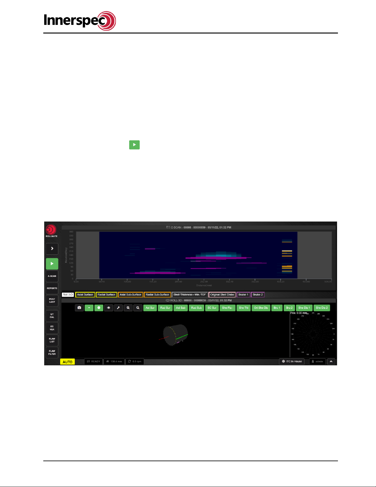
3.3. Inspection Results
Data will be displayed in two windows:
Top Window:
•Displayed C-Scan (Inspection results displayed as a heatmap).
•The X-axis is the distance along the roll.
•The Y-axis represents the circumference of the roll.
Colored areas indicate defects. The color corresponds to the test types listed at the top of the lower
window.
Bottom Window:
•Select the data to be displayed from the list across the top of the window.
Test Display Controls:
Flaw List –Displays a list of all flaws for the current roll.
Flaw Filter –Highlights flaw indications with size above a set threshold.
oRoll-3D displays a dynamic 3-dimensional image of the roll and its flaws.
oFlaw tests (Axial, Radial, Shell tests) display the maximum and minimum amplitude of the
UT signal for each rotation. Indications above the dashed threshold line will be shown as
defects in the C-Scan window with color matching the frame around the test type.

ROLLMATE User Guide
RM_A22 Page 7 of 35 ISO 9001:2008 Registered
oBruise tests (EC Surface) display the maximum and minimum magnetism for each rotation.
oShell Thickness tests display a scatter graph indicating the thickness trend of the roll shell.
Controls for Flaw Tests:
Enables/Disables the test.
Adds/Removes the results from the C-Scan (top) window.
Display/Hide the threshold line.
Note: Clicking the title bar for the current window will enable/disable these controls.
ROLLMATE User Guide
RM_A22 Page 8 of 35 ISO 9001:2008 Registered
4. Calibration / Verification
ROLLMATE uses two fixtures for calibration and verification. One fixture is used for calibrating the UT
channels and one fixture is used for verification of the EC channels.
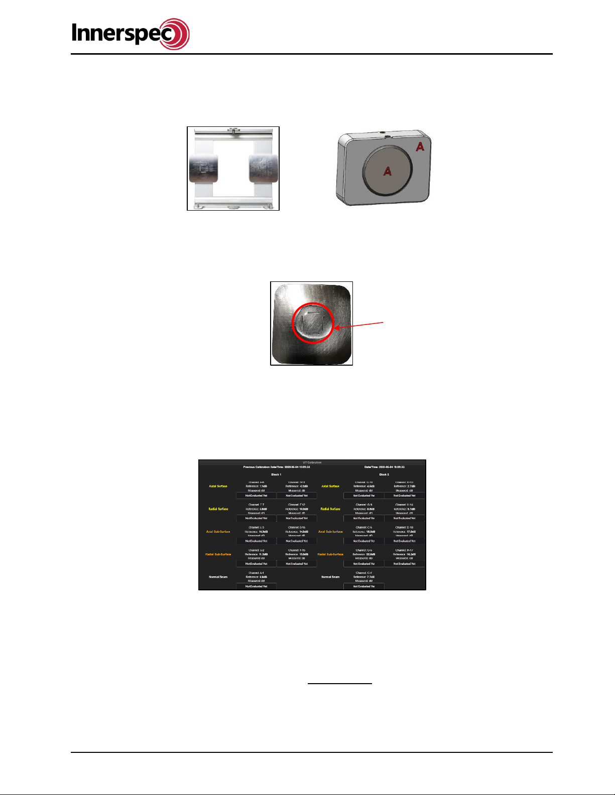
4.1. UT Calibration
The following steps are for calibrating the UT sensors for ROLLMATE:
1. Apply couplant on the two UT calibration blocks as shown below:
2. Click on the UT CAL button in Automatic Mode.
3. A Video with instructions on how to install the calibration fixture will start. Click “Accept”.
4. Install the calibration block as shown in the video.
5. Click “Yes” to begin the calibration.
6. If the calibration has passed. Click “Yes”.
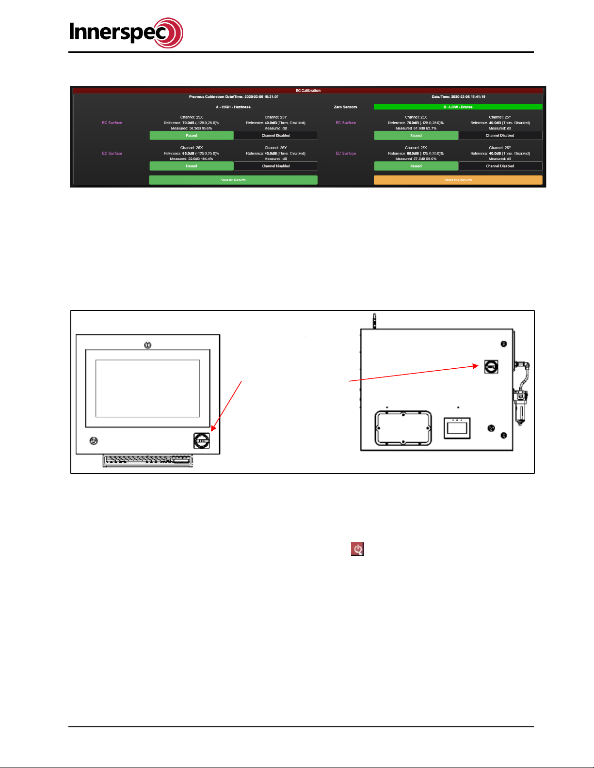
4.2. EC Verification
The following steps are for the verification of EC sensors for ROLLMATE by confirming sensors read
appropriate values for hardness and softness chips.
1. Click the EC VER button in Automatic Mode
2. Instructions will display for zeroing, click Accept.
3. Wait for ROLLMATE to zero the EC sensors while in the air.
4. A video with instructions on how to install the verification fixture will start. Click Accept to start.
5. Wait for the verification for side A to be complete.
6. A video with instructions for sliding the fixture to side B will begin. Click Accept to start.
7. Wait for the verification for side B to be complete.
The couplant needs to encompass
all of the calibration notches
ROLLMATE User Guide
RM_A22 Page 9 of 35 ISO 9001:2008 Registered
8. Verification for the EC is complete.
If either verification fails, refer to the troubleshooting section of this guide, or contact Innerspec
Technologies for assistance.
5. Power Up/Down Sequence
The following steps are how to safely power ON ROLLMATE:
1. Move the Power Disconnect Switch, located at the top-right of the DAC cabinet to the ON position.
2. Turn the E-stop button to the right and ensure the LED light is green.
3. Check and ensure that control valve(s) for couplant are open.
The following steps are to safely power OFF ROLLMATE:
1. Ensure that no scan is currently in progress.
2. Fully retract the sensor head (if extended)
3. Click “F11”then click on the “/” in the top right corner of the software. This will minimize the NDT-
WEB into a tab that can be re-opened in the bottom-left corner.
4. Next click on the power button in the bottom-right corner.
5. A menu will pop up. Click “Shutdown” this will power down the computer. Wait a minute for the
computer to power down.
6. Press the E-Stop in and move the Power Disconnect Switch to the OFF position.
Power Disconnect
Switch

ROLLMATE User Guide
RM_A22 Page 10 of 35 ISO 9001:2008 Registered
6. Accessing ROLLMATE
ROLLMATE can be operated from the DAC cabinet or remotely from a device connected to the same
network.
Logging into ROLLMATE from the DAC:
1. After powering ON ROLLMATE, System Manager will boot.
2. Click “Go to NDT-WEB a login screen will be presented on the monitor.
3. Enter the operator’s username and password. The default username and Password is:
oUsername: admin
oPassword: admin
4. ROLLMATE will then start in Automatic mode.
Logging into ROLLMATE remotely:
1. Make sure ROLLMATE is powered ON. (Skip to step four if view mode is only needed)
2. From the system Press F11 to close out of the NDT-WEB, and right-click on the desktop to open
the file manager.
3. Navigate to /home/Innerspec/data/rollmate/server/customers and open the “ip_index”. Now type in
the IPs, one per line, which you want to have access to ROLLMATE. Save, and Restart
ROLLMATE.
4. Next open System Manager you will see the IP address for wired connections at the top of the
screen.
5. On a remote device, open the Google Chrome web browser and enter the IP address followed by
port “:4000” in the search bar, e.g., 10.10.8.23:4000
6. When the login screen appears, enter the operator’s username and password.
ROLLMATE User Guide
RM_A22 Page 11 of 35 ISO 9001:2008 Registered
7. Operation Modes
ROLLMATE has different modes of operation. Automatic mode, A-Scan (Oscilloscope) mode, View mode,
and Report modes are all described in the following sections.
7.1. Automatic Mode
ROLLMATE starts in Automatic Mode when the system is initially powered ON. This mode is used for
automated roll inspection and creating/loading a Roll ID.
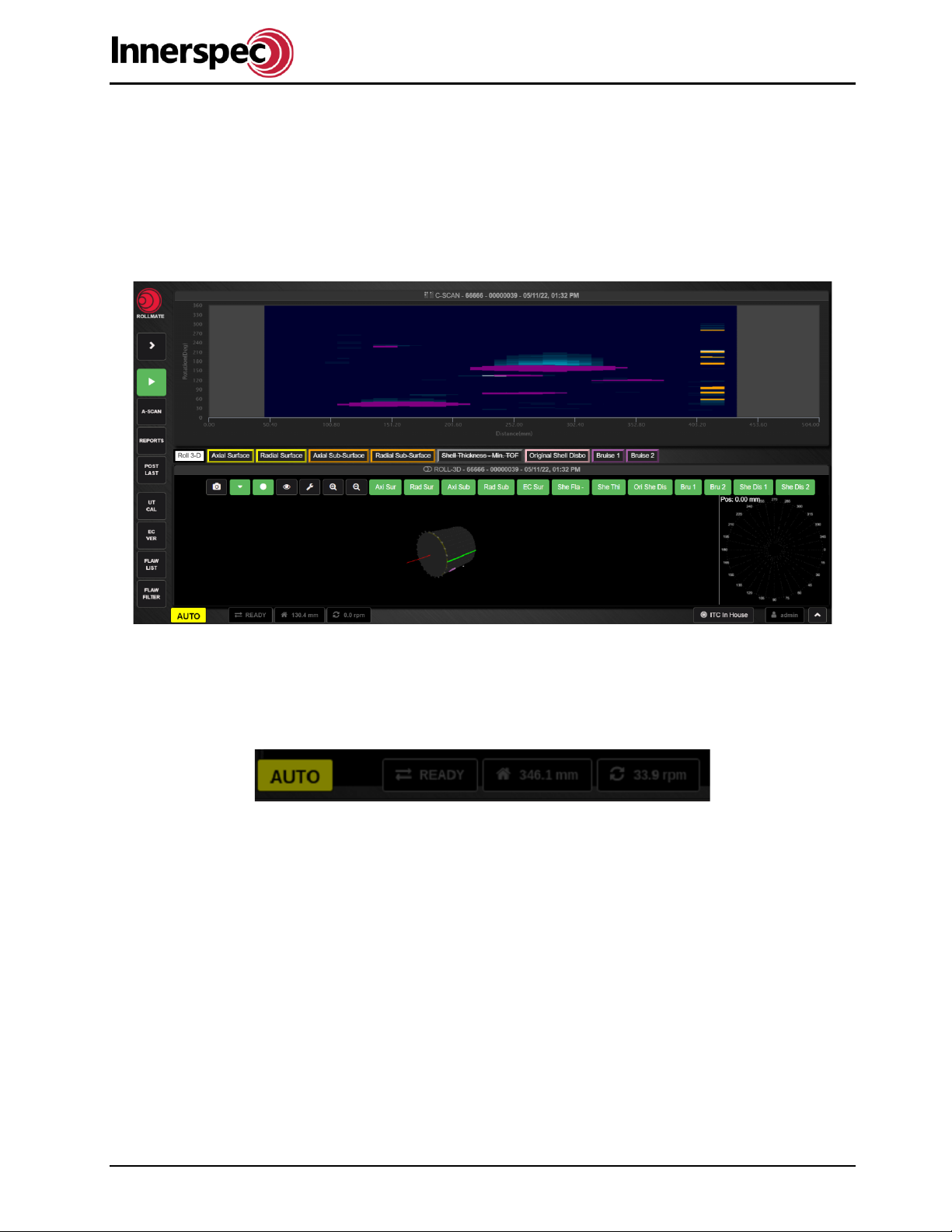
7.1.1. Communication panel
The communication panel is found on the bottom left of the home screen. In the communication panel the
operation mode, communication status, actuator and linear position, and rotation are all displayed.

ROLLMATE User Guide
RM_A22 Page 12 of 35 ISO 9001:2008 Registered
The operation mode changes as you navigate through the different areas within the software.
The status for communication with the arm “instrumentation box”.
The status for linear and actuator position.
ROLLMATE User Guide
RM_A22 Page 13 of 35 ISO 9001:2008 Registered
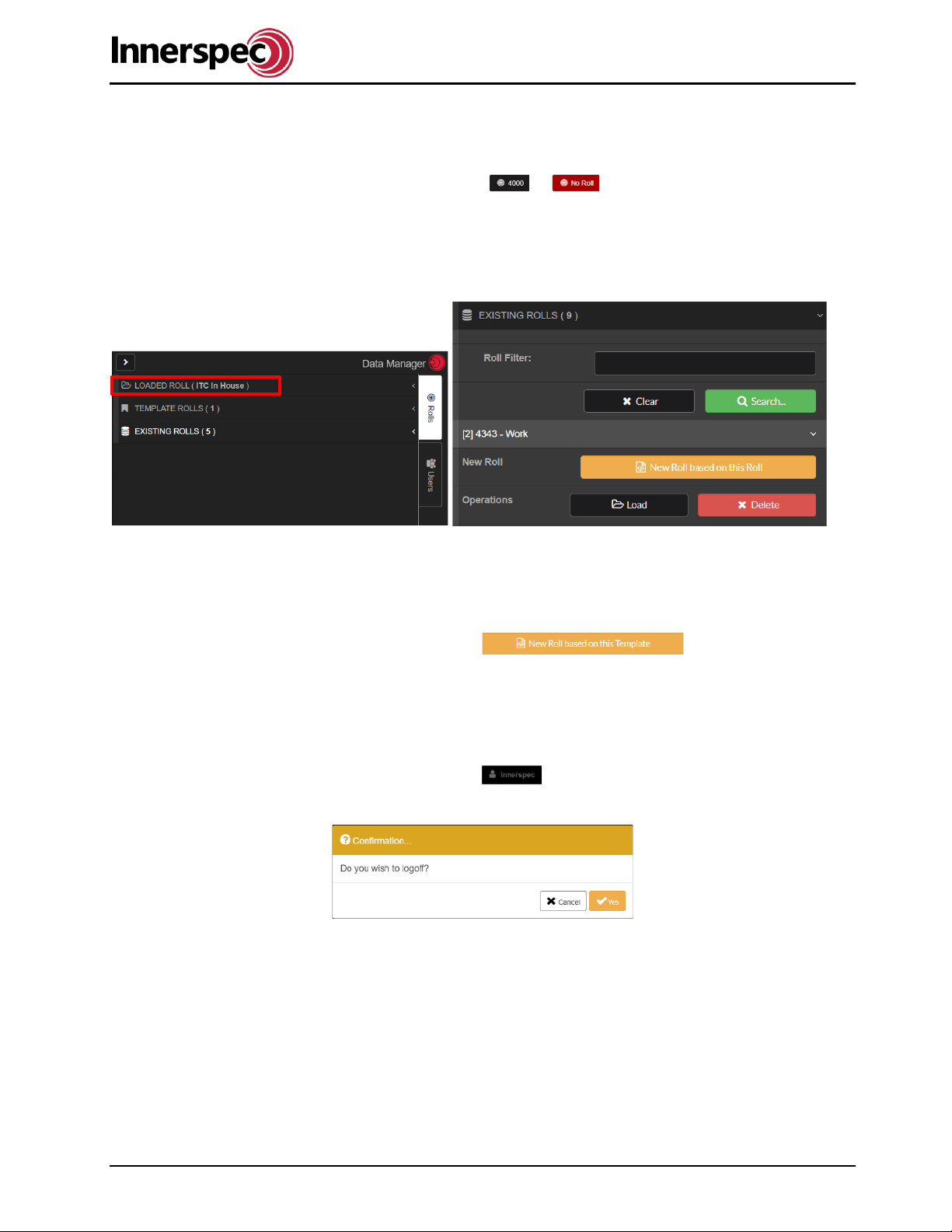
7.1.2. Selecting a Roll ID
The following steps are for loading a Roll ID:
1. Click on the Roll ID button (lower left toolbar). or
2. The Data Manager Menu will open up.
3. Click “Existing Rolls”.
4. Select the Roll ID for the roll to be inspected from the dropdown list.
5. A dropdown menu will show displaying the information of the Roll ID, click “Load” at the bottom of
the dropdown menu.
7.1.3. Creating a Roll ID
The following steps are for creating a new Roll ID:
1. Select the TEMPLATE ROLLS tab.
2. Select the desired template roll.
3. Select New Roll based on this Template.
4. Enter the roll ID name.
5. The roll can now be found in EXISTING ROLLS by searching the name.
7.1.4. Switching Users
The following steps are for switching Users:
1. Click on the “Current User” (lower left toolbar)
2. Click “Yes” to log off.
3. Enter the credentials of the other user at the login screen and click “Login”.
7.1.5. Communications & System
Click on the sidebar button in the top left corner to see the communications and system tabs.

ROLLMATE User Guide
RM_A22 Page 14 of 35 ISO 9001:2008 Registered
7.1.5.1. Encoder
Under the communications tab is the encoder setup. The encoder uses a 4-20mA signal that varies with the
inspection carriage position. The ticks will move with the inspection carriage. The inspection carriage is the
carriage the sensor head is mounted on. To calibrate the encoder:
•Move the inspection carriage to one side of its travel range.
•Enter the position the inspection carriage is reading. (Confirm units see section 7.1.5.5.)
•Move the inspection carriage to the other side of its travel range.
•Enter the position the inspection carriage is reading. (Use correct units)
•Move the inspection carriage to the middle of the roll and ensure the ROLLMATE position and the
inspection carriage position match.
Scan Direction: Tells the software which UT cluster in the sensor head is on which side.
Buttons in Auto: This allows you to set the encoder while in auto mode.
7.1.5.2. PLC
The PLC will be populated with values when the PLC is communicating with the software. If not, the System
manager PLC IP setting should be checked along with network cables. This section provides you with the
following PLC data for viewing:
•Max. Range
•Far Deadband
•Near Deadband
•Min. Range
•Scan & Head Delay
•Couplant Delay
•Sensor 1 reading
•Sensor 2 reading
•Sensor 3 reading
•Sensor 4 reading
These values can also be found and some even changed from the HMI.
7.1.5.3. Sensor Head
This gives you control over the movements of the actuator. Assuming you are within the head and tail limits
of the loaded roll and the HMI is on Auto or monitor screens. The following commands for controlling the
movements of the actuator:
•Move to roll limit
•Jog out to roll
•Stop
•Jog away form roll
•Move to limit away from roll
ROLLMATE User Guide
RM_A22 Page 15 of 35 ISO 9001:2008 Registered
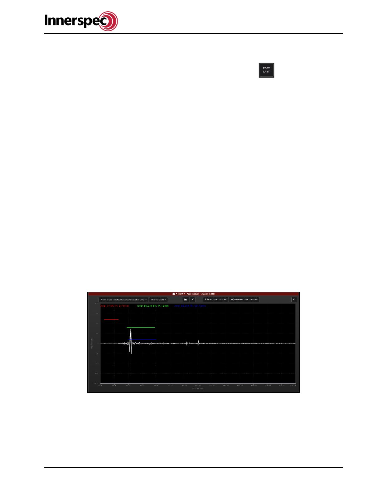
7.1.5.4. Remote Server API
When using a Rest API, you can enable it here and input post last inspection URL. The REST API is ideal
for setting up record data collection for each scan. There is also a “post-Last”button on the Main
screen for manually sending the last records requested API data.
For more information on setting up your REST API contact Innerspec for the REST API documentation.
7.1.5.5. Regional
Select the desired measuring system:
•Metric
•English
7.1.5.6. Sensitivity
Increases or decreases the overall system signal sensitivity. The default sensitivity should be 80%. Do not
adjust unless Innerspec has been consulted.
7.1.5.7. Network
This gives you a quick list of the networks connected to the PRIMO.
ENP3S0 = PLC IP
ENP4S0 = INSTRUMENTATION IP
WLP2S0 = WIFI IP
OTHER = Wired IP
7.2. A-Scan (Oscilloscope) Mode
A-Scan Mode is used for adjusting the inspection parameters for the UT channels and EC channels. Below
are examples of good signals from different channels:
*Note signals may differ slightly but the signal under the green gate should still be 80%.
Axial and Radial Surface channels

ROLLMATE User Guide
RM_A22 Page 16 of 35 ISO 9001:2008 Registered
Axial and Radial Sub-Surface channels
Normal Beam channels
7.2.1. Restore Setups
The Setup defines the gains used for the different channels given the material. To restore the setups to a
past version the following steps should be followed:
1. Click on the A-Scan Button.
2. Click on the “Restore Setups” button in the bottom right corner.
3. Select a backup file so you can restore the system.
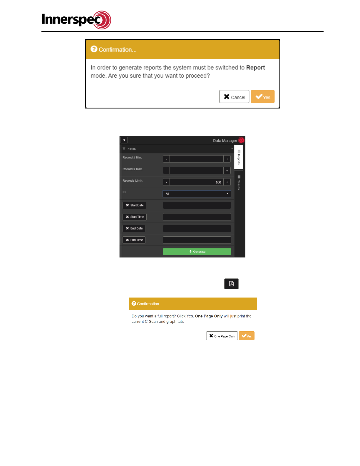
7.3. Report Mode
Report Mode is used to generate a summary report of individual roll scans. It can also be used to search for
past scans performed on specific/range-of rolls or dates.
The following steps are for loading an inspection and making a report.
•Click the “Reports” button.
•Click “Yes” to switch to Report Mode. The background will turn purple. No scans can be performed.
ROLLMATE User Guide
RM_A22 Page 17 of 35 ISO 9001:2008 Registered
•Enter in the information for the appropriate fields and click “Generate”
•The record results of the query will show in the “Results” tab.
•Click on the desired record.
•Click the PDF icon to download a report of the loaded record.
•Select either One Page Only or Yes.
a. One Page Only will display the C-Scan and the information about the roll, date of scan, and
the record number
b. Yes, will display a full report, the cover page will be the same as One Page Only followed
by the data from the different tests enabled; Axial Surface, Radial Surface, Axial and Radial
Sub-Surface, Shell Thickness, Shell Disbond both Bruise Channels.
•ROLLMATE will begin creating a report of the record.
ROLLMATE User Guide
RM_A22 Page 18 of 35 ISO 9001:2008 Registered
7.3.1. Loading an Inspection Record
To load an inspection record:
1. Ensure the system is in Reports mode.
2. Use the filter to find the desired record.
3. Double-click on the record and it will be loaded.
6. Select the Roll ID for the roll to be inspected from the dropdown list.
7. A dropdown menu will show displaying the information of the Roll ID, click “Load” at the bottom of
the dropdown menu.
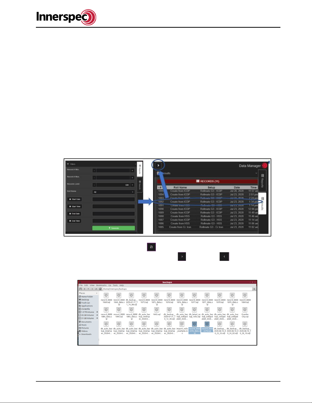
7.3.2. Exporting Report Files
Report files (.sql files) can be exported and saved to removable media. The following steps go over how to
export .sql files.
While in Report Mode:
•Use the Filters to find the records you wish to generate. Click on the report of interest. The report
will display on the view screens. Close out of the tab by clicking on the arrow at the top of the
results.
•A new button will appear below the UT calibration to generate the SQL files in the database. For
each record two .sql files are generated.
•The user can view different reports/scans by selecting for NEXT and for PREVIOUS.
•Open file manager, navigate to home/Innerspec/data/database/backups. There you will find the
two .sql files.
•These files can now be copied to removable media.
Note: If you have multiple files to send you must repeat steps 3-5 and generate a SQL file set for each
record.

ROLLMATE User Guide
RM_A22 Page 19 of 35 ISO 9001:2008 Registered
7.4. View Mode
Users with limited access will only be able to view the system, but will not be able to adjust settings.
8. HMI Main Screen
The HMI home screen will show errors and system status, and provide navigation to the other screens. It is
located on the control panel and can be remotely accessed at the remote monitor using the default IP
address: 192.168.0.2
8.1. Monitor
While the system is running you can also leave the HMI on the monitor screen, this screen shows all inputs
and outputs received and sent from ROLLMATE, grinder, and software. This screen also provides the last
sequence step performed, last retract sequence, and deviation. Deviation corresponds to how far
above/below the actuator head is from the required target roll gap. Tap on the lower right-hand corner of the
screen for a brief description of the last retract sequence.
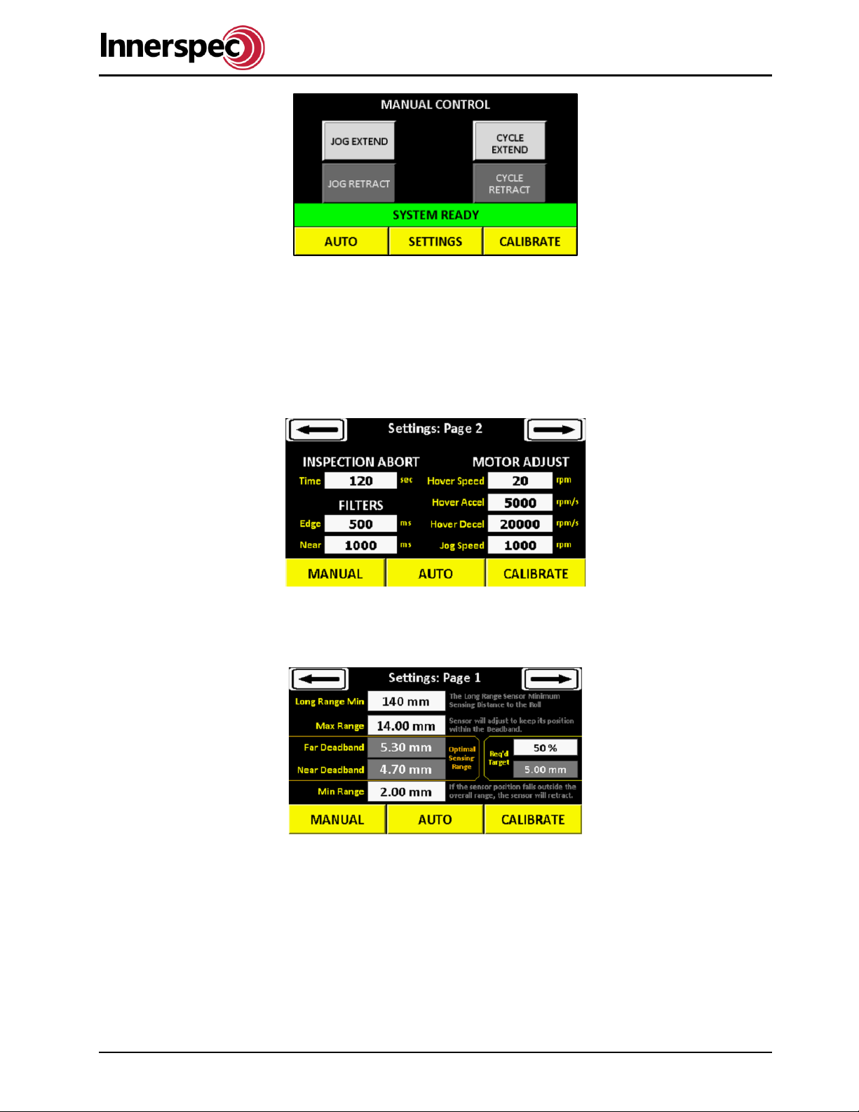
8.2. Manual
This screen allows the operator to either momentarily jog or cycle the sensor to move it. Cycling will extend
and retract the sensor in one movement either to the home position or the roll.
ROLLMATE User Guide
RM_A22 Page 20 of 35 ISO 9001:2008 Registered
8.3. Settings
8.3.1. Motor Adjust
The Motor Adjust screen allows the operator to define the parameters for the motor. Hover speed,
accel/decel, and jog speed can be adjusted here. The Filters set a time span for the roll sensors must be
out of range before retracting. Inspection abort sets a time the actuator can be away from its home position
without scanning before aborting and retracting.
8.3.2. Position Adjust
The position adjusts screen allows the operator to set ranges for the Long-Range Min, Max/Min Range, and
see the pre-set Far/Near Deadband.
8.3.3. Extra settings
Here you can enable and disable the side sensors. Adjust the hovering settings, or start and end scan
delays. Also, a Restore Defaults button is available. HMI settings will not be saved if HMI is updated. Please
have all HMI settings copied down.
Other manuals for ROLLMATE
1
Table of contents
Popular Industrial Equipment manuals by other brands


Keba
Keba KeContact P20 installation guide

Excelitas Technologies
Excelitas Technologies OmniCure AC4 Series user guide

Emerson
Emerson Rosemount 3051S Series Technical note

Mayr
Mayr EAS-NC Installation and operational instructions

ABB
ABB HT613153 Operation manual

MPS
MPS RL01SH Installation and operating instructions


