manuals.online logo
Brands
  1. Home
  2. •
  3. Brands
  4. •
  5. Zephyr
  6. •
  7. Industrial Equipment
  8. •
  9. Zephyr ZGS-12000-4 User manual

Zephyr ZGS-12000-4 User manual

This manual suits for next models

1

Other Zephyr Industrial Equipment manuals

Zephyr ZGS-11000-2 v2 User manual

Zephyr

Zephyr ZGS-11000-2 v2 User manual

Zephyr ZGS-12000-7 User manual

Zephyr

Zephyr ZGS-12000-7 User manual

Zephyr ZOM-12000-9v1 User manual

Zephyr

Zephyr ZOM-12000-9v1 User manual

Zephyr ZGS-12000-1 User manual

Zephyr

Zephyr ZGS-12000-1 User manual

Popular Industrial Equipment manuals by other brands

ABB +Q957 user manual

ABB

ABB +Q957 user manual

G.B.C BASIC EDGE 50 instruction manual

G.B.C

G.B.C BASIC EDGE 50 instruction manual

Tronair Batpak 11-6602-1000 Operation & service manual

Tronair

Tronair Batpak 11-6602-1000 Operation & service manual

Pilz PNOZ mi2p Operation manual

Pilz

Pilz PNOZ mi2p Operation manual

Clemco Zero BNP 6012 manual

Clemco

Clemco Zero BNP 6012 manual

Erskine Attachments V-Plow Operator's manual

Erskine Attachments

Erskine Attachments V-Plow Operator's manual

ABB HT610965 Operation manual

ABB

ABB HT610965 Operation manual

Morra MH 540 user manual

Morra

Morra MH 540 user manual

Eaton S090ST manual

Eaton

Eaton S090ST manual

GRIGGIO G 240 P4 instructions

GRIGGIO

GRIGGIO G 240 P4 instructions

Nexen AIR CHAMP HT45 user manual

Nexen

Nexen AIR CHAMP HT45 user manual

WTE V5 installation manual

WTE

WTE V5 installation manual

ABB HT845232 Operation manual

ABB

ABB HT845232 Operation manual

SMC Networks CJP Series Operation manual

SMC Networks

SMC Networks CJP Series Operation manual

JohnDow Industries JDI-AFT58 Operator's manual

JohnDow Industries

JohnDow Industries JDI-AFT58 Operator's manual

IMB MB9016A instruction manual

IMB

IMB MB9016A instruction manual

Clarke CUMB1 Assembly & operating instructions

Clarke

Clarke CUMB1 Assembly & operating instructions

amiad Arkal Spin Klin 2 user guide

amiad

amiad Arkal Spin Klin 2 user guide

manuals.online logo
manuals.online logoBrands
  • About & Mission
  • Contact us
  • Privacy Policy
  • Terms and Conditions

Copyright 2025 Manuals.Online. All Rights Reserved.

Fixed Hoist Test Facility Operation and Maintenance Manual ZOM-12000-4 rev 0
Page 1 of 33
This manual contains proprietary information and is not to be copied or disclosed without written
permission from Zephyr International LLC. Copyright 10-2-2006
ZGS-12000-4 Fixed Hoist Test Facility (FHTF)
Used in conjunction with the
ZGS-10000-2 Mobile Rescue Hoist Ground Support
Equipment (RHGSE)
Operation and Maintenance Manual
Fi
g
ure 1
Fixed Hoist Test Facility Operation and Maintenance Manual ZOM-12000-4 rev 0
Page 2 of 33
This manual contains proprietary information and is not to be copied or disclosed without written
permission from Zephyr International LLC. Copyright 10-2-2006
Fixed Hoist Test Facility (FHTF)
Purpose: The FHTF when used in conjunction with the Mobile Rescue Hoist Ground
Support Equipment (RHGSE) provides the capability to operate the rescue hoist off of
the aircraft in order to perform intermediate level maintenance and troubleshooting.
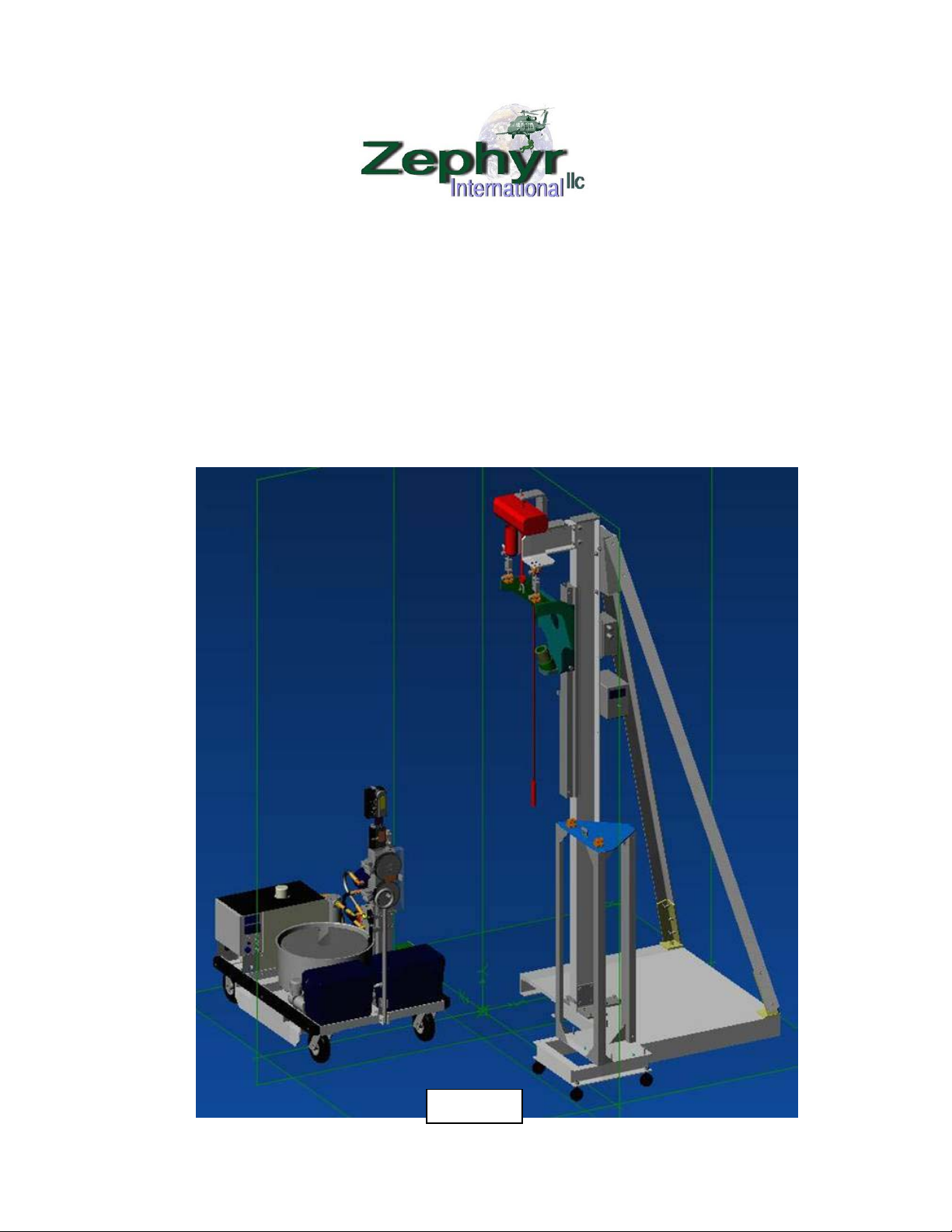
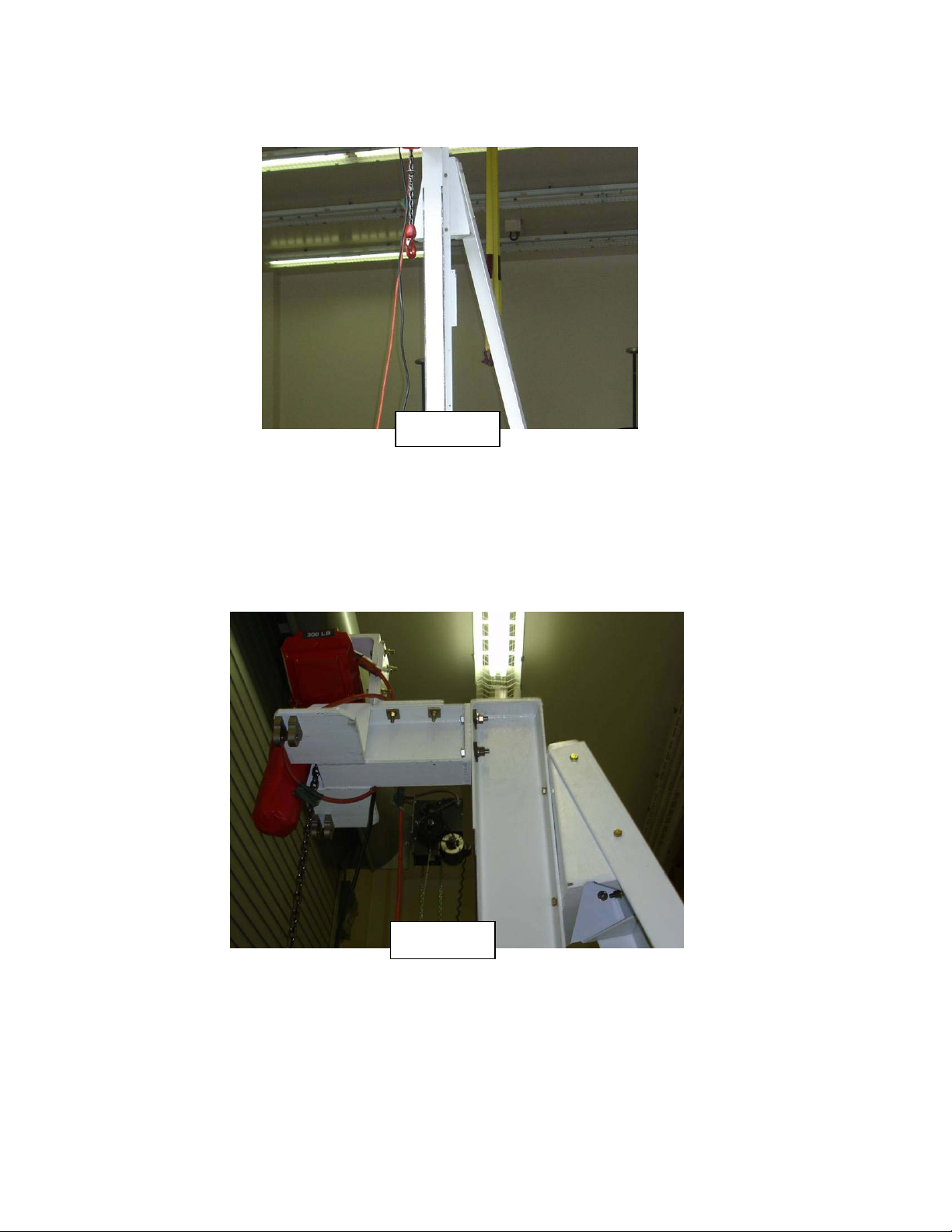
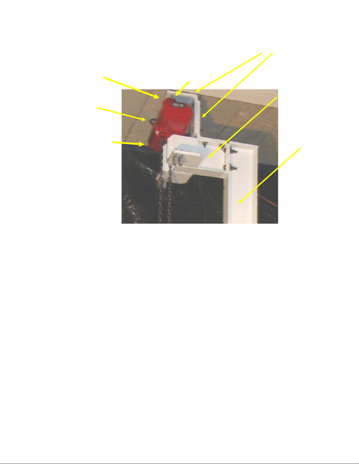
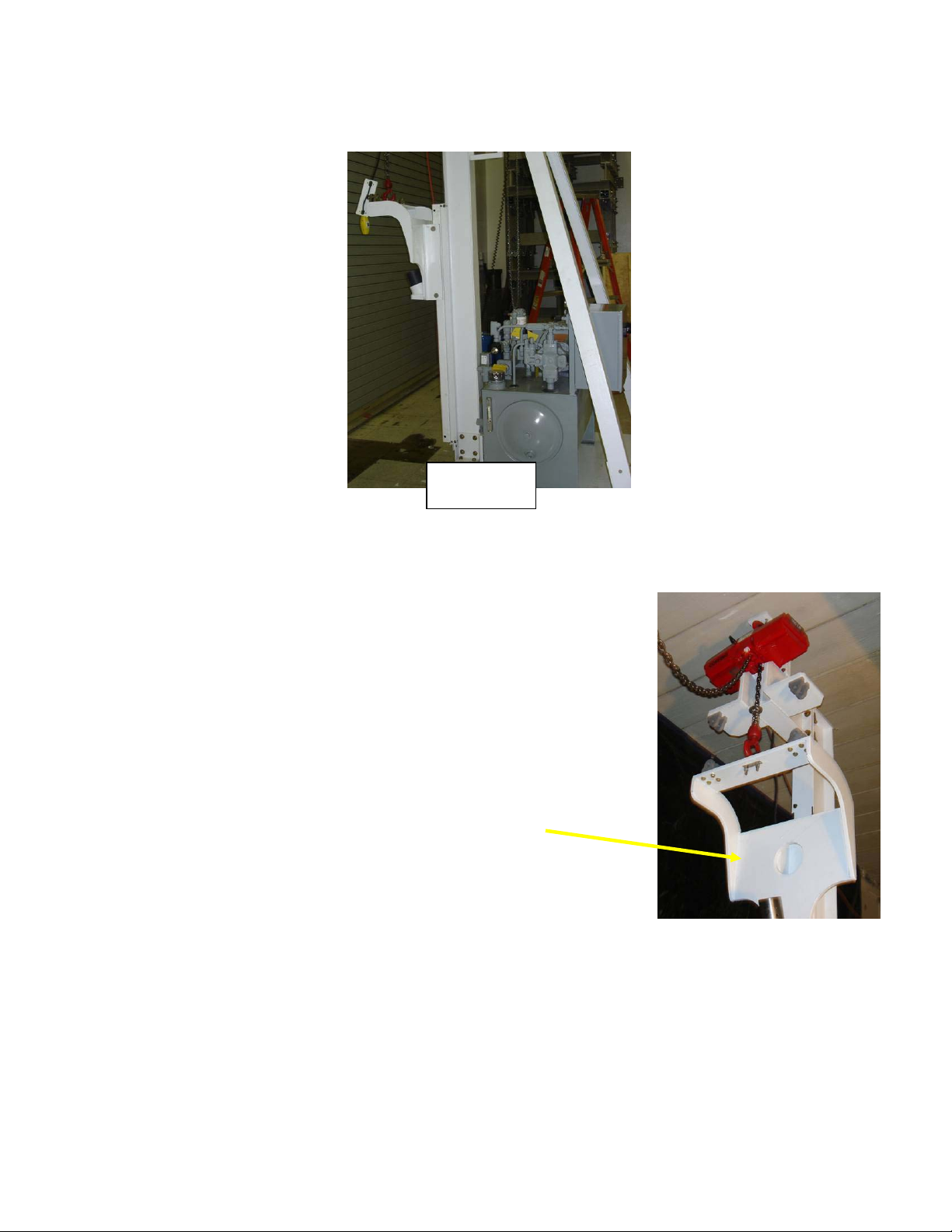
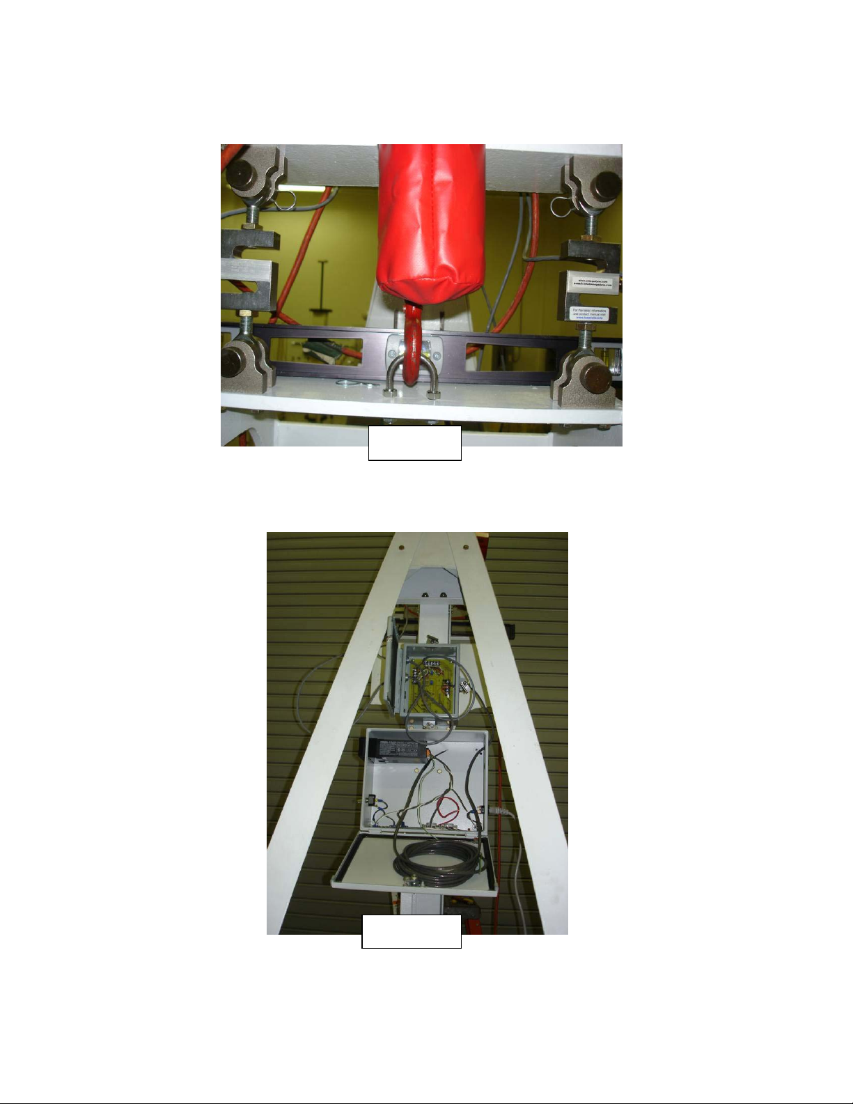
Description of FHTF: The FHTF consists of an upright structure, including an upper
weldment assembly, a hanging hoist mount, a chain hoist for raising and lowering the
unit under test (UUT), and a load weigh system. The UUT power and control signals
are provided by a customer supplied set of controllers and pendant and power supply.
Theory of Operation: The upright structure is equipped with a chain hoist to raise
the UUT up to the top of the structure where it is attached to two load cells. The two
load cells provide signals to a load cell summing box where the signals are summed
and sent to a display. The load readout can be set to zero to tare the readout with no
load applied to the rescue hoist hook.
The wire rope tensile load is provided by the RHGSE. The RHGSE provides the
capability to extend the wire rope under approximately 100 lbs. maximum load, and
provides the capability to retract the wire rope under approximately 600 lbs. maximum
load.
FHTF Limitations:
The FHTF is not intended to provide the capability to perform a complete acceptance
test as per the OEMs requirements but to allow the maintenance personnel to perform
checks of the system performance, set the hoist’s limit switches, adjust the levelwind,
and replace and condition the wire rope before the UUT is mounted onto the aircraft;
thus minimizing aircraft down time and flight time required if those procedures were
carried out on the aircraft.
Modifications to achieve full ATP capability
The FHTF has been supplied as requested without an auxiliary hydraulic power
supply, however with some modifications the FHTF and the RHGSE can be upgraded
to perform a complete ATP of the UUT. Please contact Zephyr International LLC for
details.
Fixed Hoist Test Facility Operation and Maintenance Manual ZOM-12000-4 rev 0
Page 3 of 33
This manual contains proprietary information and is not to be copied or disclosed without written
permission from Zephyr International LLC. Copyright 10-2-2006
System Pictures:
The Location Installation Requirements:
oShould be far from aircraft or equipment movement.
oShould be as close as possible to the AC power plug.
oShould be located away from any other activities in the hanger, in order to
prevent any injuries which might occur to the personnel while they are focusing
on the UUT and RHGSE.
Figure 2
Fixed Hoist Test Facility Operation and Maintenance Manual ZOM-12000-4 rev 0
Page 4 of 33
This manual contains proprietary information and is not to be copied or disclosed without written
permission from Zephyr International LLC. Copyright 10-2-2006
System Floor Plan:
Figure 3
Fixed Hoist Test Facility Operation and Maintenance Manual ZOM-12000-4 rev 0
Page 5 of 33
This manual contains proprietary information and is not to be copied or disclosed without written
permission from Zephyr International LLC. Copyright 10-2-2006
System Interconnect Diagram -NA Interconnecting cables are to be provided
by Goodrich
Assembly of FHTF:
oUnpack the crates and verify all the parts arrived in good condition.
oSlide the base plate into close proximity of its final position. Insure the floor is
clear of any debris before sliding the plate off the pallet into position.
oWith two people or a crane stand up the I beam upright
oPlace the attaching brackets into position See figure 4
oAttach all the bolts.
oOnce all bolts are in place and the beam has been positioned, tighten all
bolts securely.
oAttach the lower diagonal mounts as shown in figure 5.
Figure 5
Figure 4
Fixed Hoist Test Facility Operation and Maintenance Manual ZOM-12000-4 rev 0
Page 6 of 33
This manual contains proprietary information and is not to be copied or disclosed without written
permission from Zephyr International LLC. Copyright 10-2-2006
Attach the upper diagonal mount and then the diagonal mounts as shown in figure 6.
Attach the upper hoist mount weldment and the chain hoist support brackets as shown
in figure 7.
Figure 7
Figure 6
Fixed Hoist Test Facility Operation and Maintenance Manual ZOM-12000-4 rev 0
Page 7 of 33
This manual contains proprietary information and is not to be copied or disclosed without written
permission from Zephyr International LLC. Copyright 10-2-2006
Attach the upper weldment and hoist support as shown in figure 8, using two people or
a crane and a ladder:
oAttach the upper weldment to the upright beam
oAttach the two hoist support angles as shown.
oAttach the crane hoist with the U bolt provided and secure the upper hook of
the hoist to the hoist support angle.
oAttach the chain capture bag to the hoist and place the chain inside the bag.
Attach the lower stop bracket to the I beam to support the slider assembly.
Figure 8
Upper Weldment
Upright Beam
Hoist Support Angles (2qty)
Hoist Crane
Chain Capture Bag
Not shown
U Bolt
Upper Hook (of hoist)
Fixed Hoist Test Facility Operation and Maintenance Manual ZOM-12000-4 rev 0
Page 8 of 33
This manual contains proprietary information and is not to be copied or disclosed without written
permission from Zephyr International LLC. Copyright 10-2-2006
Attach the slider assembly using the fixed and adjustable cam follower rollers as
shown in figure 9.
Adjust the (4) adjustable cam followers so there is .002 to .005 inches clearance
between the inside face of the I-Beam and the cam follower.
Attach an extension cord to the hoist and lower the chain to attach the hanging hoist
mount.
Lift the hanging hoist mount assembly into place and attach it to the slider assembly
with the Pins as shown in Figure 11.
Figure 10
Cam Followers
Fixed Follower Eccentric Follower
Fi
g
ure 9
Fixed Hoist Test Facility Operation and Maintenance Manual ZOM-12000-4 rev 0
Page 9 of 33
This manual contains proprietary information and is not to be copied or disclosed without written
permission from Zephyr International LLC. Copyright 10-2-2006
Hanging Hoist Mount
Figure 12
Raise the hanging hoist mount and slider assembly and
verify it raises and lowers smoothly with no binding. As
shown on figure 12.
Figure 11
Fixed Hoist Test Facility Operation and Maintenance Manual ZOM-12000-4 rev 0
Page 10 of 33
This manual contains proprietary information and is not to be copied or disclosed without written
permission from Zephyr International LLC. Copyright 10-2-2006
Attach the load cells and install the upper pins as shown in figure 13. Use a level to
adjust the rod ends such that the hanging mount assembly is level.
Install the load cell summing box and wire the load cells as shown in drawing ZGS-
12340-1.
Figure 13
Figure 14