Innes DMB400 User manual
User Manual
DMB400
4.10.11 001A
1

Legal Notice
User Manual DMB400 4.10.11 (001A_en)
© 2017 Innes SA
Rights and Responsibilities
All rights reserved. No part of this manual may be reproduced in any form or by any means whatsoever without the written permission of the publisher. The products
and services mentioned in this document may be trademarks and/or trademarks of their respective owners. The publisher and the author do not pretend to these
brands.
Although every precaution has been taken in the preparation of this document, the publisher and the author assumes no responsibility for errors or omissions, or for
damages resulting from the use of the information contained in this document or the use of programs and source code who can accompany it. Under no circumstances
can the publisher and the author be held responsible for any loss of profits or any other commercial prejudice caused or that would have been caused directly or
indirectly by this document.
Product information
The conception and specifications of the product may change without prior notice, and this applies to hardware, embedded software and this guide. Consumable items
accessories may slightly differ than herein described as INNES is depending on the evolutions of its suppliers. This document contains confidential information; it can’t be
disclosed to any third parties without prior written authorization of INNES.
Safety instructions
Please read carefully the following instructions before switching the product on: - WARNING! Correct fitting and installation is of the utmost importance. Incorrect fitting
and/or installation may result in personal injury or loss. INNES disclaims all liability, of whatever kind, if the product is assembled, fitted and/or installed in an incorrect
manner. - Do not use the product near a water supply. - Do not pour anything on the product, like flammable liquids or material. - Do not expose the product to direct
sun, near a heating source or a dust nor vibrations. - Do not obstruct holes, to be sure that air flows freely around the product. - Switch off the product during a storm. -
Do not open the product in any circumstances.
Guarantee terms
INNES products are eligible for a warranty to cover genuine manufacturing defect for 3 years. Product failure occurring as the result of factors that do not constitute
genuine manufacturing defect are not covered under the terms of the warranty and any repairs of this nature would be chargeable. For example: Inappropriate
maintenance action, a non-authorized modification, a not specified environment utilization (see ‘Safety instructions’), or if the product has been damaged after an
impact, a fall, a bad manipulation or a storm consequence, an insufficient protection against heat, moisture or frost. This warranty is not transferrable. In addition, any
repairs carried out by non-authorized personnel will invalidate the warranty.
WEEE Directive
This symbol means that your end of life equipment must not be disposed of with household waste but must be deposited at a collection point for waste electrical and
electronic equipment or to your reseller. This will benefit the environment. In this context, a system for collecting and recycling has been implemented by the European
Union
2

1.1
1.2
1.3
1.4
1.5
1.6
1.7
1.8
Table of Contents
Introduction
Getting started with the device
LEDs behaviour
Connectors pin-out
Technical specifications
Troubleshooting
Conformities
Contacts
3

1.1 Introduction
This manual explains how to setup your device DMB400.
Recommendations and warnings
This device is designed to be used inside a building.
This device is intended to work with the supplied power supply unit. This power supply unit must be connected to a mains socket conforming to standard NF C 15-100. If
the AC power cable is damaged, it must be replaced. It is possible to order a replacement mains unit by sending a request to the email address [email protected].
This device is a Class A device. In a residential environment this device may cause radio interference. In this case, the user is asked to take appropriate measures.
Content of the package
Item Feature
Device DMB400 with Gekkota OS embedded
Power Supply Unit 12V Power Supply unit with cable of 1.2m
Label PSN (Product Serial Number) on the packaging and on the device
4

1.2 Getting started with the device
Front face
1 Antennas
2 Power supply connector
3 Audio connector
4 USB2 3.0 connector
5 RS232 DTE connector
6 HDMI output connector
Rear face
7 Antennas
8 Power supply Red Led
9 Status Green Led
10 LAN RJ45 connector
11 Infrared connector
12 HDMI input connector
13 USB1 2.0 connector
Device fixture
VGA
100
200
4,5 mm
7,5 mm
Device dimensions
ANT 3 ANT 4
HDMI1 OUT
RS232 DTE
AUDIO
DC IN USB2
DMB400
1
2
3
4
5
6
1
HDMI IN
ANT 1 ANT 2
IR
LAN USB1
STATUS
POWER
7
8
9
10
11
12
13
7
5

39 mm
190 mm
100 mm
200 mm
134 mm
ANT 3 ANT 4
HDMI OUT
RS232 DTE
AUDIO
DC IN USB2
DMB400
HDMI IN
ANT 1 ANT 2
IR
LAN USB1
STATUS
POWER
Labeling
The model of the device, its power supply characteristics, its serial number (PSN) as well as its MAC address are written on a label stuck on the case. Additional tags may
be present in case of built-in options.
☛ The serial number of the device can be requested in case of technical support.
6

Device start-up step
Testcard
The device is configured at the factory to start on the test pattern. The chart displays important information to assist in configuration:
Disable the testcard by using the WebUI.
Step 1 (T0=0s)
Device start-up initialisation
Step 2 (T~23s)
Device start-up finalisation
This phase duration is depending on some variable values
(like NTP), some network access duration or some data
checking (check-disk)
Step 3 (T~44s)
Nominal mode
During this step, the device has to play the content.
When firmware upgrade process occured, in
case DNS valid & NTP server inactive, it takes
~2min50s.
>
7

1.3 LEDs behaviour
LED POWER behaviour (power on device)
State Information
Red OK: Power supplied
Off Error : Power supply issue ¹
LED LAN behaviour (power on device)
State Information
Off There is no network traffic on the Ethernet connector
Blinking The blinking frequency is indicating the data rate on Ethernet connector
LED STATUS behaviour depending on device start-up steps
• Step 1 : Device start-up initialisation
State Information
Green: continuous OK
Always Off Error : Power supply issue ¹
• Step 2 : Device start-up finalisation
State Information
Off OK. This step duration can be from several seconds to several minutes.
Green blinking: 1 second duration flash and periodicity every 2 seconds Error: Boot issue ¹
• Step 3 : Nominal mode
State Information
Green blinking: 1 very short flash
(150 ms) and periodicity every 4
seconds
OK
Green blinking: 2 very short and
consecutive flashs (150 ms) and
periodicity every 4 seconds
Warning: Fail Soft Mode Level 1
De fréquents redémarrages de l'appareil ont été constatés (par exemple, 4 redémarrages en 10 minutes).
Un message est affiché à l'écran «Mode dégradé: attente d'un nouveau contenu».
L'instabilité a été causée probablement par un média de votre contenu qui n'est pas encore supporté par l'appareil. En
conséquence, pour prévenir de futur redémarrages inutiles, le contenu a été invalidé. Le message indique qu'une nouvelle
publication est requise pour jouer à nouveau le contenu. ²
Green blinking: 3 very short and
consecutive flashs (150 ms) and
periodicity every 4 seconds
Warning: Fail Soft Mode Level 2
De fréquents redémarrages de l'appareil ont été constatés (par exemple, 4 redémarrages en 10 minutes).
Un message est affiché à l'écran «Mode dégradé: attente d'un nouveau contenu».
Le contenu a été effacé et des valeurs de préférences utilisateur ont été restaurées. Le message indique qu'une nouvelle
publication est requise pour jouer à nouveau un contenu. ²
Green blinking: 4 very short and
consecutive flashs (150 ms) and
periodicity every 4 seconds
Warning: Check disk
The device has detected memory corruption on content storage. The media storage is being repaired. This repair step is
called Check-Disk and its duration can be several minutes. During this step, a message “checking the file system of data
partition in progress” is displayed on screen. ³
Green blinking: 5 very short and
consecutive flashs (150 ms) and
periodicity every 4 seconds
Warning: errors on system partition
The user has to connect to device WebUI, go to Maintenance > Tools menu, and press button Format or Repair to solve the
problem. ³
Green blinking: 6 very short and
consecutive flashs (150 ms) and
periodicity every 4 seconds
Warning: a firmware update is pending
During this phase, no content is played on the device, do not switch OFF the device.
Green blinking: 7 very short and
consecutive flashs (150 ms) and
periodicity every 4 seconds
Erro: write problem on the storage
For an unknown reason, your storage space isn't usable any more. ³
Off Error. ¹
¹ If the problem persists despite an appropriate power-supply, contact INNES technical support.
² If the problem persists, it is advised to find out the media not supported yet by the system and remove it from content.
³ If the problem persists after a partition repair, contact INNES technical support.
8
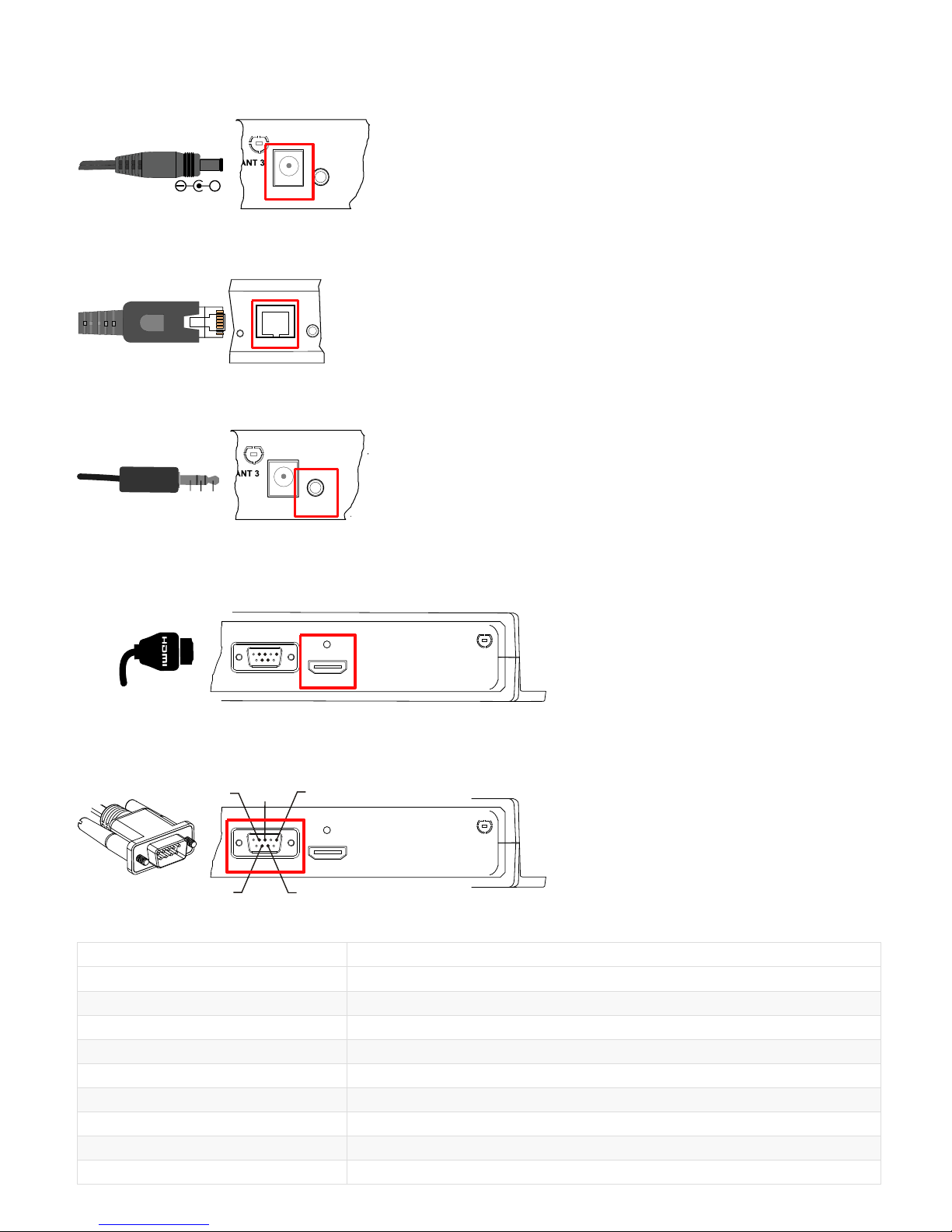
1.4 Connectors pin-out
Power supply connector (12VDC-1.2A)
+
AUDIO
DC IN
DMB400
Lan connector
Ethernet RJ-45. 10/100/1000 BaseT. It is recommended to use shielded cables.
IR
LAN
STATUS
Stereo jack 3.5mm L+R audio cable connector
It is recommended to use cables whose length is less than 3 meters.
GND
R
L
AUDIO
DC IN
DMB400
Video output connector (HDMI 2.0)
This connector is used to connect a screen or video projector.
1 2 345
678 9
ANT 4
HDMI1 OUT
RS232 DTE
RS232 DTE connector
It is recommended to use cables whose length is less than 3 meters.
1 2 345
678 9
RXD TXD GND
CTS
RTS
ANT 4
HDMI1 OUT
RS232 DTE
Connector pin-out
N° Function
1 CD
2 RXD
3 TXD
4 DTR
5 GND
6 DSR
7 RTS
8 CTS
9 -
9
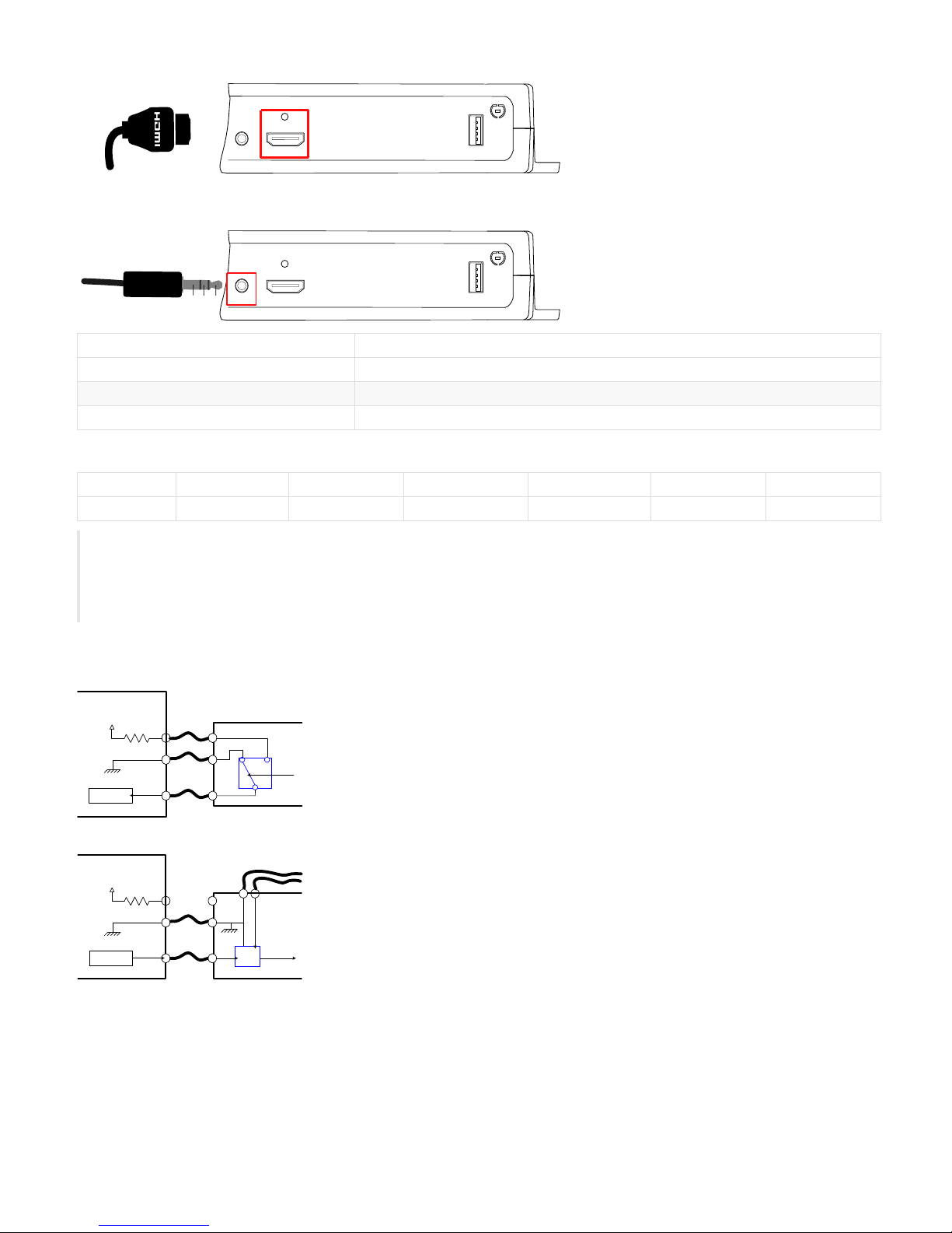
Video input connector (HDMI 1.4)
HDMI IN
ANT 2
IR USB1
GPIO1/IR Jack connector 3.5mm
321
HDMI IN
ANT 2
IR USB1
N# Function
1 3.3V
2 GPIO1/IR
3 GND
Electrical features
Vin min Vin max VOH min VOL max VIH min VIL max
GPIO1 -0.5V 3.6V 2.9V 0.4V 2.0V 0.8V
⚠
• The 3.3V pin must not serve has power supply, but rather of a reference voltage.
• It is not recommended to hotplug/unplug GPIO1 connector, it could provoke a failure of device.
• During boot, the GPIO1 is configured in input during some seconds. And then after the system startup, the GPIO1 is operational.
• The GPIO has a weak pull-up.
Principle schematics for several use cases
3 wires input configuration :
3.3V
GPIO_in
DMB400
switch
Input
Output configuration :
3.3V
GPIO_out
DMB400
Logic gate, transistor or opto-coupler
Output
Power supply
+-
10

Configuration
GPIO1 connector configuration can be done through system preferences edition with device WebUI or with a script file. GPIO1 configuration part for this script is
described here:
// Set the direction : input or output
if (aDirection == "out")
{
Services.prefs.setBoolPref("innes.app-profile.gpio-input.jack35-gpio_1.jack35_1.*.authorized", false);
Services.prefs.setBoolPref("innes.app-profile.gpio-output.jack35-gpio_1.jack35_1.*.authorized", true);
Services.prefs.setBoolPref("system.connector.jack35_1.1.io.jack35-gpio_1.enabled", true);
}
else if (aDirection == "in")
{
Services.prefs.setBoolPref("innes.app-profile.gpio-input.jack35-gpio_1.jack35_1.*.authorized", true);
Services.prefs.setBoolPref("innes.app-profile.gpio-output.jack35-gpio_1.jack35_1.*.authorized", false);
Services.prefs.setBoolPref("system.connector.jack35_1.1.io.jack35-gpio_1.enabled", true);
}
else if (aDirection == "disable")
{
Services.prefs.setBoolPref("innes.app-profile.gpio-input.jack35-gpio_1.jack35_1.*.authorized", false);
Services.prefs.setBoolPref("innes.app-profile.gpio-output.jack35-gpio_1.jack35_1.*.authorized", false);
Services.prefs.setBoolPref("system.connector.jack35_1.1.io.jack35-gpio_1.enabled", false);
}
11

1.5 Technical specifications
Model Manufacturer
DMB400 INNES
Processors
CPU Quad core cortex-A9, 1.2GHz
GPU MALI-400
Peripherals
1x USB 2.0 Host (Low/Full/High Speed)
1x USB 3.0 Host (Low/Full/High/Super Speed)
1x Jack 3.5 configurable in GPIO or Infrared
1x RS232 DTE
Storage
Internal Flash Memory for OS
SSD mSata
Software
eLinux 3.10.92
Board Support Package 3.50.10
Middleware Gekkota OS 4.10.11
Audio outputs
Jack 3.5 R+L stereo analog
Embedded with HDMI output
Video output
1x HDMI 2.0
Display resolutions for video output
640x480 60Hz, 800x600 60Hz VESA, 1024x768 60Hz VESA, 1024x768 60Hz XGA, 1024x576 60Hz VESA, 1024x576 50Hz VESA, 1024x600 60Hz DENSITRON 84-0188-
001T, 1280x720 60Hz CEA-861, 1280x720 50Hz CEA-861, 1280x720 60Hz VESA, 1280x720 50Hz VESA, 1280x720 60Hz SMPTE (720p), 1280x720 50Hz SMPTE (720p),
1280x720 60Hz CEA, 1280x720 50Hz CEA, 1280x720 60Hz SONY, 1280x720 60Hz CGV CPLine AV-HD, 1280x720 60Hz SAMSUNG, 1280x768 60Hz VESA, 1280x768
50Hz VESA, 1280x800 60Hz VESA, 1360x768 50Hz VESA, 1360x768 60Hz VESA, 1376x768 60Hz VESA, 1376x768 50Hz VESA, 1376x768 60Hz PC, 1920x1080 60Hz CEA-
861, 1920x1080 50Hz CEA-861, 1920x1080 60Hz VESA, 1920x1080 50Hz VESA, 1920x1080 60Hz SMPTE (1080p), 1920x1080 50Hz SMPTE (1080p), 1920x1080 60Hz
CEA, 1920x1080 50Hz CEA, 3840x2160 59.94Hz, 3840x2160 60Hz CEA-861, 3840x2160 50Hz CEA-861, 3840x2160 50Hz VESA, 3840x2160 30Hz CEA-861, 3840x2160
25Hz CEA-861, 2560x1440 60Hz CEA-861, 3840x600 60Hz VESA, 1920x540 60Hz VESA, 128x96 60Hz, 112x96 60Hz, 96x96 60Hz
Video input
1x HDMI 1.4b
Preferred resolutions of EDID for Video input
1920x1080p 59.94Hz, 1920x1080p 60Hz, 1920x1080p 50Hz, 1280x720p 59.94Hz, 1280x720p 60Hz, 1280x720p 50Hz, 1920x1080i 59.94Hz, 1920x1080i 60Hz,
1920x1080p 29.97Hz, 1920x1080p 30Hz
Network
1x Ethernet 10/100/1000 BaseT
Options
WIFI 802.11 b/g
GPRS/EDGE/HSDPA Modem
12

Power supply
12V DC (1.2A)
Working temperature Storage temperature
0°C to +40°C -20°C to +60°C
Working humidity Storage humidity
< 80% < 85%
Weight Dimensions (WxHxD)
0,7 kg 191 x 139 x 40 mm
13

1.6 Troubleshooting
Error while playing a media: message "Content temporarily unavailable <media path/file name> (code <err>)"
Requirement Troubleshooting
code 404 (error code HTTP 404 = file not found)
Publish again the playout on the device after having checked, that:
- the media used is really existing
- your playlist do not refer to obsolete medias
code 403 (error code HTTP 403 = access denied) The remote media is not available
code 401 (error code HTTP 401 = authorization required) The login/password required to play the medias is not correct
code 0 (media not supported at all by your device) Remove the media and publish again ¹
code 1 (an error occurred when the media has been inserted in the
dom) An error occurred when playing the media ²
code 2 (error during viewer activation (play) An error occurred when playing the media ²
code 3 (media repeat error) An error occurred when playing the media ²
code 4 Media not supported by your device. Remove the medias from your playout and publish
again
code 5 (event error on control xhr) Change the media behavior value to try to solve the issue
code 6 (event abort ou timeout sur xhr de control) Change the media behavior value to try to solve the issue
Error while playing a media: message "This content <media path/file name> is not compatible with this device"
Troubleshooting
To solve the issue, remove this not supported media from your playout and publish again. ¹
¹ For further information, read the document gekkota-supported-medias-and-performances.pdf
² For further information, contact [email protected]
14

1.7 Conformities
In conformity with the following European directives:
LVD 2014/35/EU
EMC 2014/30/EU
15

1.8 Contacts
For further information, please contact us at + 33 (0)2 23 20 01 62 or by e-mail:
Technical support: [email protected]
Sales department: [email protected]
FAQ and download at : http://www.innes.pro/en/support/
INNES SA
5A rue pierre joseph Colin
35700 RENNES
Tel: +33 (0)2 23 20 01 62
Fax: +33 (0)2 23 20 22 59
http://www.innes.pro/fr
INNES SA
Verbindungsbüro Deutschland
Lebacher Str. 4
66113 Saarbrücken
Tel: 09386-979 39-14
Fax: 09386-979 39-15
Mob : 0175 853 67 81
http://www.innes.pro/de
16
Table of contents
Other Innes Digital Signage manuals


