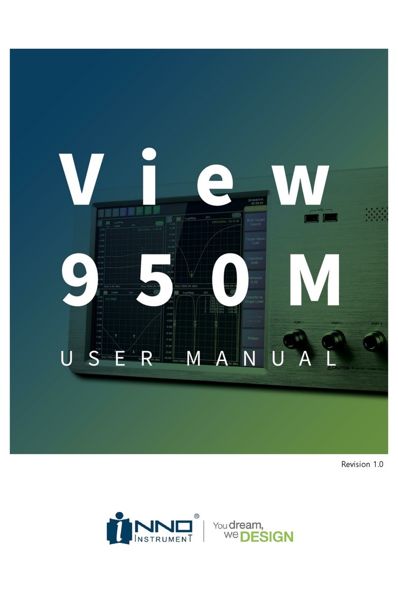
INNO View 950M User manual

Revision 1.0

View950M Multi-Scan
INNO Instrument Inc. Page 2 of 55
TABLE OF CONTENTS
1. GENERAL INFORMATION .............................................................................................................................. 4
1.1. DESCRIPTION................................................................................................................................................................................5
1.1.1. KEY MEASUREMENTS............................................................................................................................ 5
1.1.2. KEY FEATURES ...................................................................................................................................... 5
1.2. THE LAYOUT OF VIEW900......................................................................................................................................................6
2. INSTRUMENT OVERVIEW.............................................................................................................................. 8
2.1. FRONT............................................................................................................................................................................................9
2.2. REAR............................................................................................................................................................................................... 9
2.3. SPECIFICATIONS .........................................................................................................................................................................10
3. MENU DESCRIPTIONS..................................................................................................................................12
3.1. MAIN WINDOW DESCRIPTION..............................................................................................................................................13
3.2. MEASURE ....................................................................................................................................................................................16
3.3. STIMULUS....................................................................................................................................................................................18
3.3.1. STIMULUS CHANGE ORDER.................................................................................................................18
3.4. SCALE ...........................................................................................................................................................................................19
3.4.1. SCALE CHANGE ORDER.......................................................................................................................20
3.5. SWEEP ..........................................................................................................................................................................................21
3.5.1. EXTERNAL TRIGGER SETUP..................................................................................................................21
3.6. DISPLAY .......................................................................................................................................................................................22
3.6.1. NUM OF TRACE &WINDOWS ICON ...................................................................................................23
3.7. MARKER.......................................................................................................................................................................................23
3.7.1. MARKER SETUP &MOVING ...............................................................................................................25
3.8. CALIBRATION..............................................................................................................................................................................26
3.9. LIMIT ............................................................................................................................................................................................26
3.9.1. LIMIT DISPLAY ACCORDING TO EACH MENU SETTING ...........................................................................27
3.10. TRACE ......................................................................................................................................................................................29
3.10.1. TRACE –DATA &MEM DISPLAY.........................................................................................................30

View950M Multi-Scan
INNO Instrument Inc. Page 3 of 55
3.11. SAVE.........................................................................................................................................................................................31
3.11.1. SLOT SAVE..........................................................................................................................................31
3.11.2. SAVE FILE TYPE...................................................................................................................................32
3.12. LOAD........................................................................................................................................................................................34
3.12.1. SLOT LOAD .........................................................................................................................................35
3.12.2. FILE LOAD...........................................................................................................................................36
3.13. SYSTEM ...................................................................................................................................................................................38
3.13.1. LAN SETUP........................................................................................................................................39
3.13.2. UPGRADE............................................................................................................................................39
3.13.3. INFORMATION.....................................................................................................................................41
4. TEST METHOD ...............................................................................................................................................42
4.1. CALIBRATION PROCEDURE ......................................................................................................................................................43
4.1.1. OSL CALIBRATION..............................................................................................................................44
4.1.2. E-CAL CALIBRATION ...........................................................................................................................46
4.2. MULTI TARGET TO SINGLE LIMIT PROCEDURE...................................................................................................................48
4.2.1. MULTI TARGET IMPLEMENTATION PROCEDURE ....................................................................................49
4.2.2. MULTI TARGET TO SINGLE LIMIT .........................................................................................................50
5. WARRANTY INFORMATION........................................................................................................................52

View950M Multi-Scan
INNO Instrument Inc. Page 4 of 55
1. GENERAL INFORMATION

View950M Multi-Scan
INNO Instrument Inc. Page 5 of 55
1.1. DESCRIPTION
With the development of mobile communication technology, frequency bands supported by smart phones
keep increasing. Accordingly, the number of antennas mounted on mobile phones is increasing as well.
Most of the antennas in smart phones or mobile phones are mounted on the rear cover. If you attach an
antenna from the antenna manufacturer to the case, you will measure only the VSWR after mounting the
case because you already use the antenna that has been tested.
When producing one mobile phone antenna, usually 4 to 6 antennas are tested. Therefore, if you want to
produce it, you have to do 2 ~ 3 tests if you test with 2 port network, 1 ~ 2 if you use 4 port network.
There is, of course, a conventional bench-type 4-port network, but it has too much specs to use on the
production line. In other words, in production lines that want to measure simple VSWRs quickly, it is
somewhat less competitive to produce using expensive 4 port networks. As competition intensified in
smart phones, production costs have been reduced, and demand for products optimized for mobile phone
antenna production has increased.
Inno-Instrument's VIEW950M is the right product to meet the needs of this market, and can be expanded
to six ports if additional options are added on the base 4 port. It is optimized for VSWR measurements
and includes the necessary functions in the mobile phone production line, allowing you to quickly and
easily reset the measurement conditions as needed.
1.1.1. KEY MEASUREMENTS
High resolution VSWR Measurements
Simultaneous sweep of 4 ports shortens measurement time
Optimized Multi Target function
Convenient Limit Setting Function
Jig stabilization time setting function
1.1.2. KEY FEATURES
Broadband Frequency Coverage : 5MHz to 6GHz
Multi-Functions : VSWR, Return Loss
Easy-To-Operate, Intuitive GUI
10.4”TFT color LCD, Touch Screen

View950M Multi-Scan
INNO Instrument Inc. Page 6 of 55
Ext. For Jig Supply. DC 24V Out
Jig Interface (32Pin)
19 "rack mountable
1.2. THE LAYOUT OF VIEW900
Image 3 types. Front photo, Rear photo, Top photo

View950M Multi-Scan
INNO Instrument Inc. Page 7 of 55

View950M Multi-Scan
INNO Instrument Inc. Page 8 of 55
2. INSTRUMENT OVERVIEW

View950M Multi-Scan
INNO Instrument Inc. Page 9 of 55
2.1. FRONT
The front of VIEW950M is shown below. There is a 10.4-inch LCD on the left and four N-type RF
ports on the right. On the top right, there are two USB ports and a power button.
Items
Quantity
Explanatikon
LCD
1
-10.4”TFT Color LCD (Touch Screen)
RF Port
4
-N-Type, 50Ω, Female
USB
2
-Type-A
-USB 2.0, 500mA
Power Button
1
-One push on/off, Blue LED
2.2. REAR
The rear part is configured as shown below. The rear left has a FAN for heat dissipation and a terminal
for grounding. On the right side, power and data related connectors are arranged.

View950M Multi-Scan
INNO Instrument Inc. Page 10 of 55
Items
Quantity
Contents
FAN
1
- Operation when power is turned on by FAN for heat discharge
Ground
1
- Terminals for ground connection
GPIO
1
- 36 pin connector with interface for external jig connection
24VDC
1
- DC 24V power supply for external jig etc.
USB
2
- Type-A
- USB 2.0, 480mA
Video Out
1
- RGB connector, Max 1920 X 1200@60Hz for LCD connection
Ethernet
1
- Ethernet terminal for external connection
3 pole AC terminal
1
- 3 pole power terminal for AC input on the device
2.3. SPECIFICATIONS
Items
Specifications
Technical
Frequency Range
5MHz to 6GHz
Number of Test Port
4 Port (Optional Max 6 Port)
Measurements
VSWR, Return Loss
Frequency Setting Resolution
10kHz
VSWR Range
1 to 65
Return Loss Range
+60dB to -60dB
Resolution
0.01dB
Max Input Level
+25dBm

View950M Multi-Scan
INNO Instrument Inc. Page 11 of 55
Output RF Power
-4dBm
Test Port
N Type Female, 50Ω
Port VSWR
<1.5
Number of Measurement Points
251, 501, 1001, 2001
Marker
Max 6 (Multi Target & Peak/Valley Search)
Scan Speed
0.6ms/point, All port scan at the same time
Ant. Measurement Function
Multi Target to Limit line automation function Limit line
function
SCPI
SCPI function equipped
Immunity
On-Frequency
+5dBm
On-Channel
+15dBm
General
Display
10.4”TFT Color LCD, 800 X 600, Touch Screen
Memory
SSD (32Gbyte)
Operating System
Windows 10
Front Connector
USB 2.0, Type A 2 Port
Rear Connector
10/100 Ethernet
USB 2.0, Type A 2 Port
36-Pin Centronics, Female
15-pin D-Sub female; VGA(Up to 1920X1200 at 60Hz)
Power Supply
AC 100 to 240V, 4.15A, 50/60Hz
Power Output
DC 24V, Max 0.5A
Sound
Buzzer, Resonant Frequency 2300Hz
Dimension
445.2mm(W) X 197.2mm(H) X 325.8mm(D)
Weight
About 11kg
Operating Temperature
0℃to +50℃
Storage Temperature
-40℃to +80℃(-40℉to +176℉)

View950M Multi-Scan
INNO Instrument Inc. Page 12 of 55
3. MENU DESCRIPTIONS

View950M Multi-Scan
INNO Instrument Inc. Page 13 of 55
3.1. MAIN WINDOW DESCRIPTION
When the equipment is turned on, the Main screen appears as shown below. Log / Mag
measurement results of 4 ports are displayed by default. The screen can be roughly divided into
three parts.
①
- Port Display Setting (Full & Multi)
- Preset execution
- Test alarm sound control
②
- Trace indicating area (Full & Multi)
③
- Side Menu area
①- Port Display setup (Full & Multi)
Selected
Not
Explanation

View950M Multi-Scan
INNO Instrument Inc. Page 14 of 55
selected
- If selected, trace screen of port 1 is displayed in full screen
- 2, 3, and 4 ports display a non-select icon
- If selected, trace screen of port 2 is displayed in full screen
- 1, 3, and 4 ports display a non-select icon
- If selected, Trace screen of port 3 is displayed in full screen.
- 1, 2, and 4 ports display a non-select icon
- If selected, Trace screen of port 4 is displayed in full screen.
- 1, 2, and 3 ports display a non-select icon
- If selected, Ports 1 to 4 display all traces on the screen.
- Each port icon is colored blue (the rest gray)
- If the port marked in blue is Active
①- Preset
Icon
Explanation
- Single port Preset execution
- Preset is executed when clicking on the currently set active port
- Execute all port Preset
- Preset on all ports immediately when clicked
①- Test alarm sound control
Icon
Explanation
- Turn off the alarm sound depending on the results of test when failing
With all 4 ports displayed, you can switch the selected port to full screen. Switching between full
screen and multi-screen can be done in two ways. One can be executed by using the Port Display
setting button, and the other can be converted by double touching the LCD in the corresponding
area. The figure below shows the switch of port 1 to full screen to explain '②-Trace display area'.

View950M Multi-Scan
INNO Instrument Inc. Page 15 of 55
The horizontal axis of the Trace display area represents the Stimulus-Frequency, and the vertical axis
represents the Scale-Amplitude. The yellow box at the top of the picture above shows the following
expression.
②- Trace indicating area
Expression
Other expressions
Explanation
- Indicate selected and non-selected port
- Indicate trace 1 and 2
- Indicate setup measure
- Indicate setup data point
-
- Indicate Run / Hold
- Indicate nothing in case of Run
-
- Indicate Cont. / Single
- Indicate nothing in case of Cont.
- Indicate Calibration On, Off

View950M Multi-Scan
INNO Instrument Inc. Page 16 of 55
‘③- Side Menu Area' contains menus to change the settings of each port. This is described in turn
from Section 3.2. Below is the top menu of VIEW950M. If you click each corresponding menu, you
can enter the submenu and change the condition of each port.
- Display top menu
- When clicked from other menu entry, go to upper menu
- Enter Measure setup menu
- Enter Stimulus setup menu
- Enter Scale setup menu
- Enter Sweep setup menu
- Enter Display setup menu
- Enter Marker setup menu
- Enter Calibration setup menu
- Enter Limit setup menu
- Enter Trace setup menu
- Enter Save setup menu
- Enter Load setup menu
- Enter System setup/confirmation menu
3.2. MEASURE
VIEW950M can display measurement result in VSWR and Log / Mag (Return loss) form. Measure is a
function to set the measurement type of the selected trace. When VSWR or Log / Mag is selected
after selecting Trace, the type of trace is applied.
- Display Measure menu
- When clicked, move to upper menu (VIEW950M)
- Change Trace indication to VSWR form
- Change Trace indication to Log/Mag form

View950M Multi-Scan
INNO Instrument Inc. Page 17 of 55
- Move to the previous menu
Measure setting confirmation can be checked by checking each Tr setting status at the top of each
port trace chart. In the figure below, port 1 is set to VSWR, ports 2 to 4 are set to Log / Mag.

View950M Multi-Scan
INNO Instrument Inc. Page 18 of 55
3.3. STIMULUS
The operating frequency of each port can be changed in the Stimulus menu. The VIEW950M's Stimulus
menu is organized as shown below.
- Display Stimulus menu
- Go to upper menu when clicked (VIEW950M)
- Change Start Freq. of selected port
- Change Stop Freq. of selected port
- Change Center Freq. of selected port
- Change Span of selected port
- Move to the previous menu
Notice
- Range of frequency to be setup is as follows.
5MHz to 6GHz
3.3.1. STIMULUS CHANGE ORDER
1. Enter Stimulus
- Select Stimulus in VIEW950M
menu
- Enter the side menu, Stimulus
2. Select items Select among Start Freq. / Stop Freq. / Center Freq. / Span
- Click the item you want to
change
- Input window appears
- Composed of trace chart and
input number of currently
selected port
3. Enter setup values

View950M Multi-Scan
INNO Instrument Inc. Page 19 of 55
- Click the item you want to
change
- Input window appears
- Composed of trace chart and
input number of currently
selected port
4. Change port or item
- Enter a number in the input
window
- Check the input value in the
upper right corner
- Unit selection. Complete input
- Simultaneous setting of all
ports at 'All Port Apply' check
3.4. SCALE
The horizontal axis of each port trace chart represents the frequency and the vertical axis represents
the amplitude. Scale includes a menu to change the vertical axis amplitude. The range that can be
set depends on the Measure setting. For VSWR, you can set the range from 1 to 65. For Log / Mag,
you can set it from -60dBm to + 60dBm. Scale menu configuration is shown below.
- Indicate Scale menu
- Move to top menu if clicked (VIEW950M)
- Change max value of Display Amplitude of selected port
- Change the min value of Display Amplitude of selected port
- Change Display Amplitude of selected port to appropriate range
- Change Display Amplitude to Full Scale of selected port
- Move to the previous menu
Notice
- Amplitude range that can be set is as follows. (When selecting Full Scale, set to the range below)
VSWR : 1~65
Log/Mag : +60dB ~ -60dB
- The Top value cannot be less than the Bottom, and the Bottom value cannot be greater than the Top.

View950M Multi-Scan
INNO Instrument Inc. Page 20 of 55
3.4.1. SCALE CHANGE ORDER
1. Enter Scale
- VIEW950M Scale selection in
menu state
- Enter the side menu Scale
2. Select Top / Bottom
- Click Top / Bottom item
- Change settings in the input
window
- Port, setting after changing item
3. Auto Scale
- Auto Scale Select the port to
execute
- Click the Auto Scale button
- Scale automatically applied to
the appropriate level
4. Full Scale
- Full Scale Select Port to Run
- Click the Full Scale button
- Scale Full Range
Other manuals for View 950M
1
Table of contents
Other INNO Measuring Instrument manuals
