Innolas Laser nanio Series Operating manual

nanio Industrial DPSS Laser
User and Installation Manual
Innolas Laser GmbH
Justus-von-Liebig-Ring 8
D-82152 Krailling
Germany

© 2009 InnoLas Laser GmbH. All rights reserved.
Revision History
1.0 First release
Release date: 15 July 2009

Customer Support Contact Addresses
InnoLas Laser GmbH
Justus-von-Liebig Ring 8
D-82152 Krailling
Germany
Tel: +49 89 899 36 0 - 0
Fax: +49 89 899 36 0 - 16
E-mail: [email protected]
InnoLas (UK) Ltd.
67 Somers Road
Rugby
Warwickshire CV22 7DG
United Kingdom
Tel: +44 1788 550 777
Fax: +44 1788 550 888
E-mail: [email protected]

Table of Contents
Preface
Audience
Other Publications
How to Use this Manual
1. Safety...........................................................................................................................................1
1.1. Qualification and training of personnel........................................................................1
1.2. Electrical.............................................................................................................................2
1.3. Laser radiation...................................................................................................................2
1.4. Location of safety labels...................................................................................................3
1.5. Refrigerant medium.........................................................................................................4
1.6. Hazardous materials........................................................................................................5
1.7. Decommissioning and disposal......................................................................................5
2. General Description.................................................................................................................7
2.1. Intended use......................................................................................................................7
2.2. Laser Head.........................................................................................................................7
2.3. Power Supply....................................................................................................................8
2.4. Chiller options...................................................................................................................8
2.4.1. Water/air....................................................................................................................8
2.4.2. Water/water..............................................................................................................9
2.5. Beam Delivery Options....................................................................................................9
2.6. Specifications.....................................................................................................................9
2.6.1. Electrical supply.......................................................................................................9
2.6.2. Dimensions.............................................................................................................10
2.6.3. Nominal weights....................................................................................................13
2.6.4. Customer connections...........................................................................................13
2.6.5. Performance............................................................................................................13
2.6.6. Environmental........................................................................................................13
2.6.7. Design lifetime of the equipment........................................................................13
3. Operation..................................................................................................................................15
3.1. Direct start up..................................................................................................................15
3.2. Direct shut down.............................................................................................................15
3.3. Remote start up...............................................................................................................15
3.4. Remote shut down..........................................................................................................16
3.5. Emergency shut down...................................................................................................16
3.6. Restart after an emergency shut down........................................................................16
4. Software....................................................................................................................................17
4.1. Default software .............................................................................................................17
4.2. RS232 control protocols..................................................................................................17
5. Routine maintenance.............................................................................................................21
5.1. Safety compliance checks...............................................................................................21
5.2. Chiller...............................................................................................................................21
5.2.1. General checks........................................................................................................21
5.2.2. Water/water............................................................................................................21
5.2.3. Water/air..................................................................................................................23

5.3. Power supply...................................................................................................................23
5.4. Laser head........................................................................................................................24
6. Troubleshooting......................................................................................................................25
7. Installation...............................................................................................................................27
7.1. Unpacking........................................................................................................................27
7.2. Positioning and mechanical mounting........................................................................27
7.2.1. Laser head...............................................................................................................28
7.2.2. Power supply..........................................................................................................28
7.2.3. Chiller......................................................................................................................28
7.3. Electrical connections.....................................................................................................29
7.4. Coolant connections.......................................................................................................30
7.5. Safety and interlock connections..................................................................................30
7.5.1. Emergency stop interlock.....................................................................................30
7.5.2. Shutter safety interlock.........................................................................................30
7.5.3. External laser emission warning lamp................................................................30
7.6. Control connections........................................................................................................30
7.7. External beam delivery components............................................................................30
7.8. Initial operation...............................................................................................................31
8. Transport and re-commissioning.........................................................................................33
8.1. Transport..........................................................................................................................33
8.2. Recommissioning............................................................................................................33
9. Interfacing................................................................................................................................35
9.1. Interlocks..........................................................................................................................35
9.1.1. Emergency stop......................................................................................................35
9.1.2. Shutter.....................................................................................................................35
9.1.3. System reset............................................................................................................35
9.2. Emission warning lamp.................................................................................................36
9.3. Q-switch control inputs..................................................................................................36
9.4. User interface...................................................................................................................36
10. Parts list...................................................................................................................................39


Preface
Audience
This manual should be read by all personnel who install or operate the nanio laser.
Important!
Read this manual carefully before operating the laser for the first time. Pay
special attention to the Safety chapter.
The nanio laser is designed and sold for use in OEM systems and is not to be used as a
stand-alone laser. The OEM is responsible for compliance with all applicable safety
regulations.
Other Publications
•EN60825–1 Radiation Safety of Laser Products, Equipment Classification, Requirements
and User's Guide
http://www.cenelec.org
•IEC 60204–1 Safety of Machinery, Electrical Equipment of Machines
•IEC 61010–1 Safety Requirements for Electrical Equipment for Measurements, Control and
Laboratory Use
•Laser Safety Guide
Laser Institute of America, 13501 Ingenuity Drive, Suite 128, Orlando, Florida
32826, USA
http://www.laserinstitute.org
•ANSI Z136.1–2000 — Safe Use of Lasers, American National Standards Institute
http://www.ansi.org/
http://www.z136.org/
•H.I.B. Systemtechnik GmbH Industrial Cooling Systems, Operating Instructions
Withdrawable Units (19 inch)
How to Use this Manual
The manual contains information required for safe operation, installation and routine
maintenance of the equipment.
nanio Industrial DPSS Laser User and Installation Manual
iPreface

InnoLas Laser GmbH
Preface ii

1. Safety
Only authorised personnel, familiar with the potential dangers presented by laser
equipment during operation or installation, are allowed to work with the laser system.
It is of utmost importance that personnel working with the system read, understand
and observe the information and instructions in this manual.
WARNING
Risk of exposure to laser radiation
Use of controls or adjustments or performance of procedures other than those
specified herein may result in hazardous radiation exposure.
The nanio is a Class IV laser intended to be used as part of an integrated laser-based
processing system.
Safe use of this equipment is reinforced by safety labels fixed to the equipment in a
visible manner. The type of safety labels used and their location is detailed in section
1.4.
The use of controls, replacement parts, adjustments, or procedures other than those
specified within this manual may result in exposure to any of these hazards.
• Laser hazards
• Electrical hazards
• Environmental hazards
• Mechanical hazards.
The degree of seriousness of the hazard is indicated by the use of the following signal
words:
DANGER
Indicates an imminent hazard which, if not avoided, is extremely likely to result in
death or serious injury.
WARNING
Indicates a potentially hazardous situation which, if not avoided, could result in
death or serious injury.
CAUTION
Indicates a potentially hazardous situation which, if not avoided, may result in
minor or moderate injury. It is also used to alert the user against unsafe working
practices and potential damage to the equipment.
1.1. Qualification and training of personnel
Personnel who install and/or operate the laser must be adequately qualified for the
work concerned and should have read this manual. the user must clearly specify the
sphere of responsibility, competence and
nanio Industrial DPSS Laser User and Installation Manual
11. Safety

1.2. Electrical
DANGER
Risk of electrocution
Switch off and disconnect the equipment from the mains electrical supply before
exposing electrical terminals. Only trained and authorised personnel should
remove covers from the power supply or water to air chiller.
DANGER
Risk of electrocution
Electrical connections must only be made by trained and authorised personnel.
Before working on the system:
• Remove the key from the key switch on the power supply.
• Turn off the mains electrical supply and, if possible, disconnect the equipment from
the supply.
• Restrict access to the area to trained people who are aware of the hazards.
• Refer to the system manual and circuit diagrams for wiring connections and
polarities. Never guess or use trial and error techniques.
• Fit only InnoLas approved parts.
• Do not operate the equipment with safety panels removed or with interlock
switches overridden (unless a key operated override facility has been included).
• Never attempt to work on electrical circuits when alone; always have a colleague
nearby.
• Observe the requirement of the electrical safety codes for the establishment where
the laser is installed.
• External equipment connected to the system must comply with EN61010–1 and
appropriate local standards.
1.3. Laser radiation
WARNING
Risk of exposure to laser radiation
Use of controls or adjustments or performance of procedures other than those
specified herein may result in hazardous radiation exposure.
During installation or in a maintenance situation, the operating area of the laser system
must be clearly marked to warn unauthorised personnel not to enter the area. All
entrances and exits must be marked with appropriate warning signs.
OEM system integrators are obliged to provide training to their customers and to make
them familiar with the potential dangers of Class IV laser in general and the nanio laser
in particular.
InnoLas Laser GmbH
1. Safety 2

When working on the system during installation or in a maintenance situation, observe
the following rules:
• Avoid eye or skin contact to direct or scattered radiation.
• Always wear protective eye wear matched to the emission wavelength of the laser.
Instruct all personnel in the vicinity to wear identical protective eye wear.
• Never look into the laser beam!
• Make sure there are no reflective materials in the beam path that could deflect the
beam toward the operator or another person in the vicinity.
• Use only non-flammable, absorbing or non-reflective materials as beam dumps.
• Never operate the laser in the vicinity of explosive liquids or gases.
• Be aware that laser processing certain materials (e.g. plastics) may create poisonous
fumes and by-products.
1.4. Location of safety labels
The labels shown on the following drawing are fitted to the equipment in the locations
specified and must not be removed or defaced. Immediately replace any missing
labels. Replacement labels can be obtained from InnoLas.
Labels on the side of the laser head are repeated on both side faces.
Figure 1 - Safety label locations
Figure 2 - Label A
nanio Industrial DPSS Laser User and Installation Manual
31. Safety
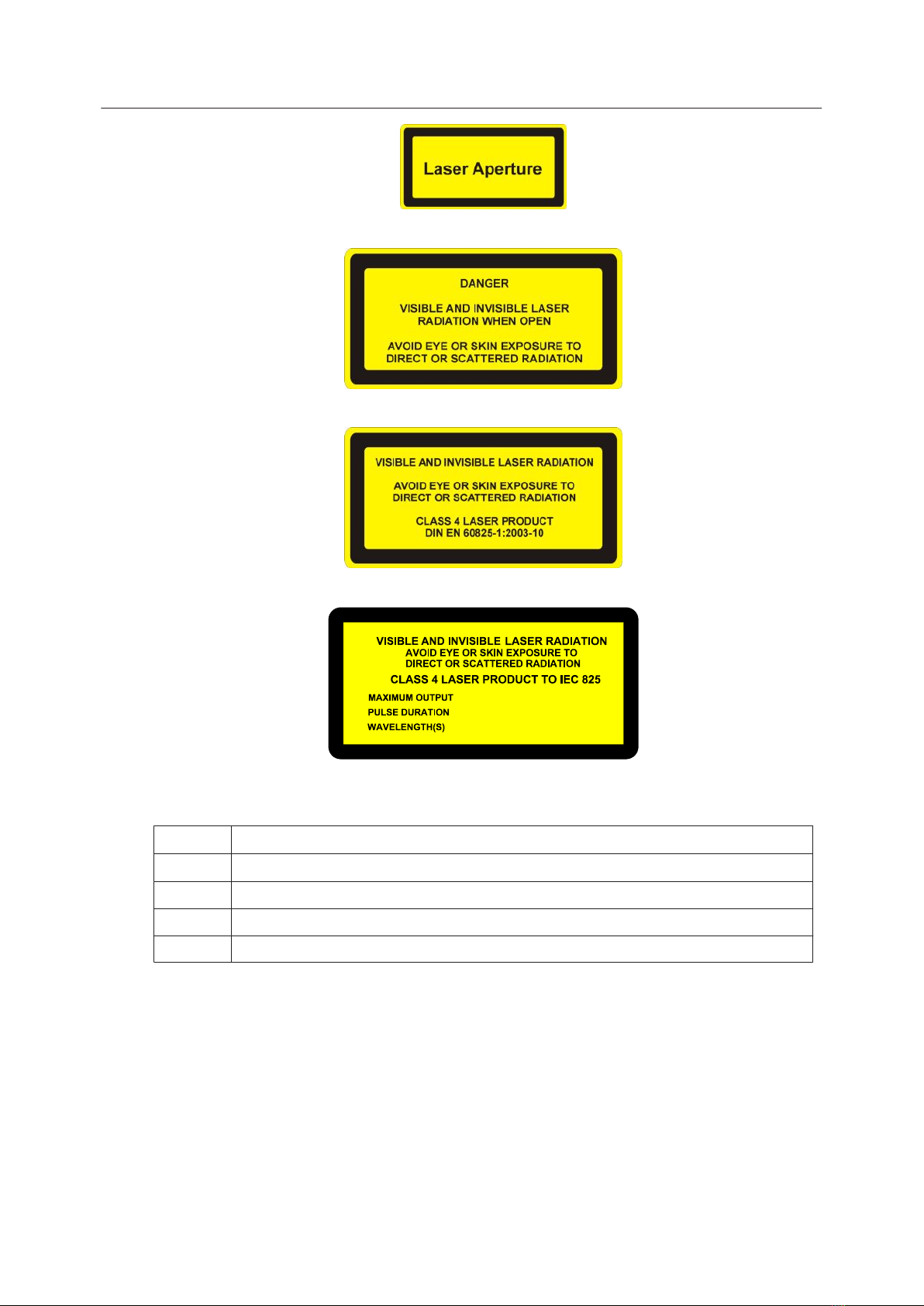
Figure 3 - Label B
Figure 4 - Label C
Figure 5 - Label D
Figure 6 - Label E
The following information appears on Label E:
Po40 W
Pp100 kW
t 20–500 ns
F Single shot to 500 kHz
λ 1064/532/355 nm
DONT FORGET THE TYPE LABEL!!
1.5. Refrigerant medium
The water/air chiller contains a refrigerant medium. Avoid direct contact with the
refrigerant.
InnoLas Laser GmbH
1. Safety 4

DANGER
Risk of explosion
Do not use a water/air chiller in an explosive atmosphere or for cooling
flammable of explosive substances.
WARNING
Risk of lung damage
Never smoke in the vicinity of a water/air chiller. If refrigerant escapes it
decomposes to form cauterising acids that can severely damage your lungs.
If the refrigerant has to be drained or replaced, the procedure must be performed by a
specialised and trained person. Discarded refrigerant must be disposed of in
accordance with ISO/DIS 11650 or an equivalent local rules and regulations.
1.6. Hazardous materials
The laser head contains indium used as a heat conductor in the diode module and all
crystal mounts. Indium is toxic. Do not open the diode modules or crystal assemblies.
1.7. Decommissioning and disposal
If the laser will be definitively taken out of service and decommissioned, disconnect
and remove all signal and power cables, disconnect the external cooling water pipes
and drain the chiller.
Dispose of a water/air chiller in accordance with EN 378–4.
Dispose of the system according to appropriate local regulations, paying particular
attention to disposal of indium components in the laser head.
nanio Industrial DPSS Laser User and Installation Manual
51. Safety

InnoLas Laser GmbH
1. Safety 6

2. General Description
2.1. Intended use
The nanio is a diode-pumped solid-state laser system designed for OEM applications
as part of an integrated laser-based materials processing system. It offers a choice of
output wavelengths and powers with repetition rates up to 500 kHz and excellent
beam quality and stability.
The laser fails safe with no beam output and therefore must not be used where the
beam is part of a safety system; for example, as a light barrier.
2.2. Laser Head
Figure 7 - Laser head
The laser head consists of a diode module and a resonator module. The resonator
module is supplied in several lengths depending on the output specification. All
electrical and cooling connections are on the end face of the diode module. Laser
ouptut is emitted from the end face of the resonator module and can be configured so
that the beam axis is to the left or right of the centre line. The laser head can be
mounted using the bottom surface (preferred) or either side face. In each case, a three-
point fixing is provided with precise and repeatable location assured by means of
precision reference holes and slots for dowel pins.
The complete assembly is sealed to prevent the ingress of dust and humidity and is
fitted with a desiccant cartridge. It is temperature stabilised by means of stainless steel
cooling pipes embedded under the base of the resonator module and into a Peltier
cooler in the diode module.
Important!
Never open the laser head unless. No user serviceable parts inside.
The laser head contains the following key components:
• One or two laser diode modules with collimating optics
• Control electronics
nanio Industrial DPSS Laser User and Installation Manual
72. General Description

• Laser crystal and resonator mirrors
• Intra-cavity accousto-optic Q-switch
Note: The Q-switch driver can be mounted on the left or right-hand side of the resonator
module, depending on the mounting method chosen for the laser head.
• Intra-cavity safety shutter with dual-redundant closure detector
In addition, it can be fitted with harmonic generation and separation modules and an
external accousto-optic modulator.
All connectors can be supplied in either inline or 90° configurations.
2.3. Power Supply
Figure 8 - Power supply
The power supply is common to all nanio lasers. This provides maximum flexibility
and minimises spare part holdings. An output is provided for the chiller. Water/water
chillers are both powered and controlled from the power supply. Water/air chillers use
an independent mains electrical connection but are controlled from the power supply.
The power supply is designed to fit into a 19–inch rack and is 2RU high.
2.4. Chiller options
2.4.1. Water/air
Figure 9 - Water/air chiller
The water/air chiller is recommended for low average power or low duty cycle
applications. It is designed to fit into a 19–inch rack and is available in low power (5RU
high) or medium power (6RU high) versions.
Water/air chillers require an unrestricted flow of air at less than 40°C.
InnoLas Laser GmbH
2. General Description 8

2.4.2. Water/water
Figure 10 - Water/water chiller
Water/water chillers are available in standard and clean-room versions. They are
designed for high average power or high duty cycle applications. Both versions fit into
a 19–inch rack and are 4RU high. External water pipe connections are xx flow and xx
return.
Water/water chillers require an external water supply with minimum flow rate of
8 l/min and pressure differential of 100 kPa
2.5. Beam Delivery Options
• Beam expander
• Scan head mounting option
2.6. Specifications
2.6.1. Electrical supply
Maximum power consumption 1.5 kVA
Maximum current demand 16 A
Supply voltage Single phase 115–230 VAC ± 10%
Supply frequency 50/60 Hz
nanio Industrial DPSS Laser User and Installation Manual
92. General Description
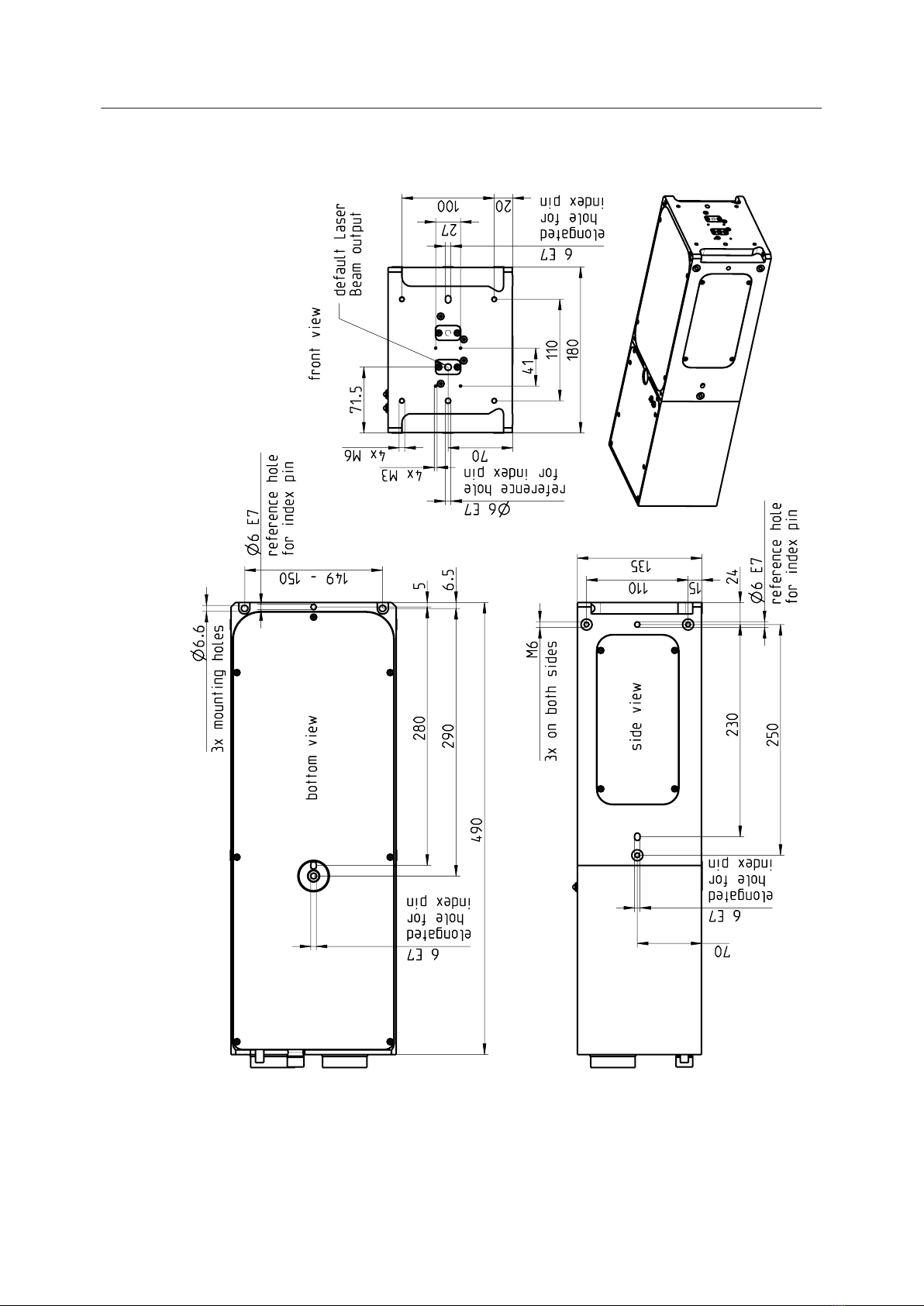
2.6.2. Dimensions
Figure 11 - 490 mm head
InnoLas Laser GmbH
2. General Description 10

Figure 12 - 590 mm head
nanio Industrial DPSS Laser User and Installation Manual
11 2. General Description
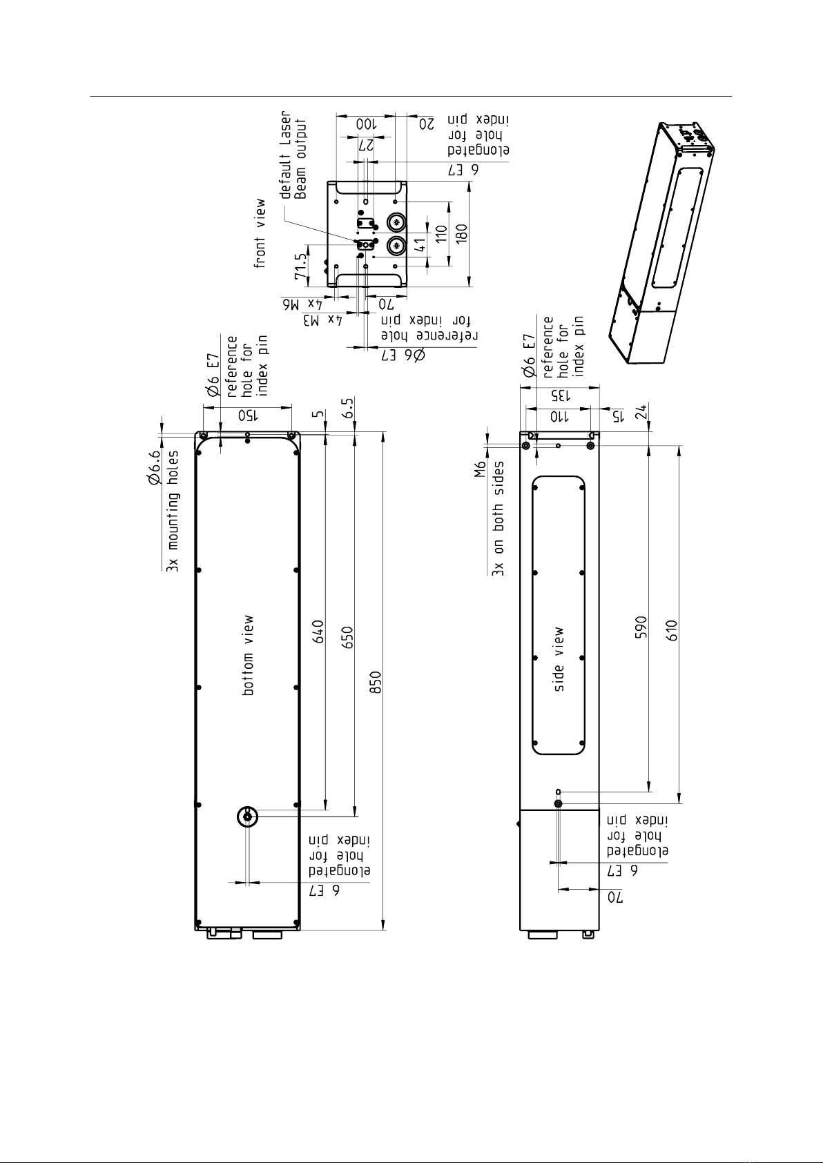
Figure 13 - 850 mm head
Umbilical cables and cooling water pipes linking laser head, power supply and chiller
have a standard length of 3 m but can be supplied in lengths from 1 m to 20 m on request.
InnoLas Laser GmbH
2. General Description 12
Table of contents


