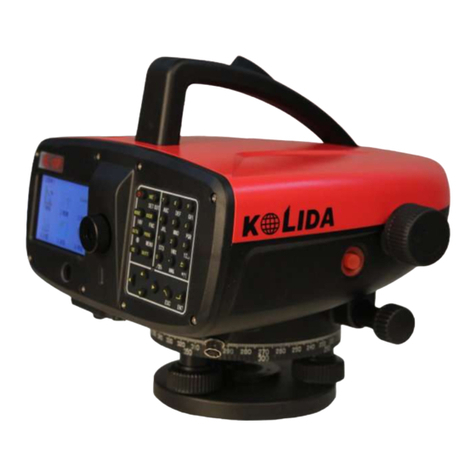
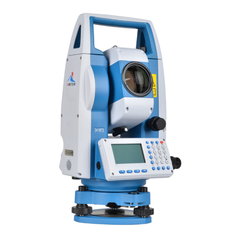
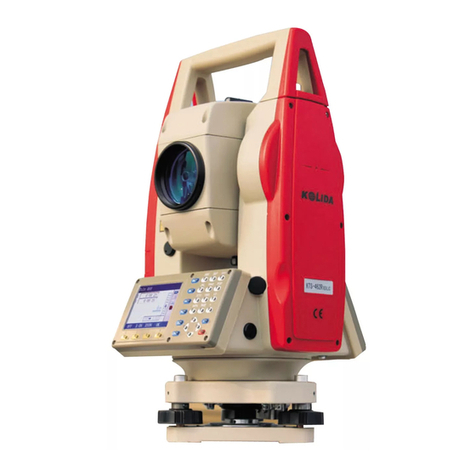
Kolida KTS440 R Series User manual

1
CONTENTS
FOREWORD
1. FEATURES ...................................................................................................................................................5
2. PRECAUTIONS...........................................................................................................................................6
3. NOMENCLATURE ....................................................................................................................................9
4. KEY FUNCTIONS.....................................................................................................................................11
5. CHARACTER ENTRY............................................................................................................................13
6. DISPLAY SYMBOLS................................................................................................................................14
7. MODE CONFIGURATION....................................................................................................................15
PART 1 PREPARATION FOR MEASUREMENT ..............................19
1. UNPACKINGAND STORE OF INSTRUMENT..............................................................................19
2. SETTINGTHE INSTRUMENT UP......................................................................................................19
3. BATTERY DISMOUNTING, INFORMATION, RECHARGING ..............................................21
4. REFLECTOR PRISMS............................................................................................................................22
5. MOUNTINGAND DISMOUNTING INSTRUMENT FROM TRIBRACH ............................23
6. EYEPIECEADJUSTMENTAND OBJECT SETTING .................................................................24
7. POWER ON/OFFAND PREPARATION FOR MEASUREMENT............................................24
7.1 Power ON/OFF ..................................................................................................................................... 24
7.2 Vertical Angle Tilt Correction............................................................................................................... 25
7.3 Display Illumination.............................................................................................................................. 27
7.4 Setting the Instrument Options............................................................................................................. 27
7.5 Setting Instrument Constant ................................................................................................................. 29
7.6 Setting LCD Contrast............................................................................................................................ 30
7.7 Setting Date and Time........................................................................................................................... 31
7.8 Explanations........................................................................................................................................... 32
PART 2 BASIC MEASUREMENTS.........................................................33
8.ANGLE MEASUREMENT.....................................................................................................................33
8.1 Measuring the Horizontal Angle Between Two Points(Horizontal Angle 0)………………34

2
8.1.1 Example Measuring the Horizontal Angle Between Two Points..............................................34
8.2 Setting the Horizontal Circle to a Required Value..............................................................................35
8.2.1 Use HSET function to set a required direction value......................................................................35
8.2.2Use HOLD to set a required direction value ....................................................................................36
8.3 Horizontal Angle Display Selection(Right /Left).........................................................................37
8.4 Horizontal Angle Repetition.................................................................................................................37
8.5 Slope in %.............................................................................................................................................39
9. DISTANCE MEASUREMENT............................................................................................................. 40
9.1 Settings for Distance Measurement.....................................................................................................41
9.2 Returned Signal Checking ....................................................................................................................43
9.3 Distance and Angle Measurement.......................................................................................................44
9.4 Review of Measured Data ....................................................................................................................45
9.5 Outputting the Data to a Computer......................................................................................................47
10. COORDINATE MEASUREMENT................................................................................................... 47
10.1 Entering Instrument Station Data.......................................................................................................48
10.1.1 Reading in Registered Coordinate Data......................................................................................... 50
10.2 Azimuth Angle Setting ........................................................................................................................51
10.3 Coordinate Measurement....................................................................................................................53
PART 3 ADVANCED MEASUREMENT ............................................... 56
11. SETTING-OUT MEASUREMENT................................................................................................... 56
11.1 Distance Setting-Out Measurement...................................................................................................57
11.2 REM Setting-Out Measurement........................................................................................................61
11.3 Coordinates Setting-Out Measurement............................................................................................. 63
11.4 Distance Measurement Parameters Setting ......................................................................................65
12. OFFSET MEASUREMENT ................................................................................................................ 67
12.1 Single-Distance Offset Measurement................................................................................................68
12.2 Angle Offset Measurement.................................................................................................................71
12.3 Two-Distance Offset Measurement...................................................................................................73
13. MISSING LINE MEASUREMENT................................................................................................... 76
13.1 Measuring the Distance Between Multiple Targets.........................................................................76
13.1.1 Measuring the distance between multiple targets .........................................................................76
13.1.2 Slope in between 2 points................................................................................................................78
13.2 Changing the Starting Point................................................................................................................78
14. REM MEASUREMENT....................................................................................................................... 79
3
15. RESECTION MEASUREMENT........................................................................................................81
15.1 Re-Observing....................................................................................................................................... 84
15.2 Add Known Points.............................................................................................................................. 85
16.AREACALCULATION………...…………………………………………………………87
17. ROAD DESIGN AND SETTING OUT……………………………………………………..89
PART 4 DATA RECORDING...................................................................118
18. SETTING IN MEMORY MODE.......................................................................................................118
18.1 JOB Selection .................................................................................................................................... 119
18.1.1 Setting for grid factor…………………………………………………………………...120
18.1.2 Changing JOB name...................................................................................................................... 121
18.2 Deleting a JOB................................................................................................................................... 122
18.3 Outputting job data to computer ...................................................................................................... 123
18.4 Receiving coordinate data ................................................................................................................ 124
18.5 Input Coordinate Data to current job............................................................................................... 125
18.6 Registering coordinate data in memory.......................................................................................... 125
18.7 sending known point data................................................................................................................. 127
18.8 Clearing coordinate data to memory............................................................................................... 128
18.9 Reviewing coordinate data........................................................................................ ……………131
18.10 Input Codes……………………………………………………………………………132
18.11 Deleting codes……………………………………………………………………… ....133
18.12 Reviewing codes……………………………………………………………………….134
18.13 Initialization……………………………………………………………………………134
19. RECORDING IN RECORD MODE ............................................................................................... 136
19.1 Recording Distance Measurement Data......................................................................................... 136
19.2 Recording Angle Measurement Data.............................................................................................. 138
19.3 Recording Coordinates Data............................................................................................................ 139
19.4 Recording Instrument Station Data ................................................................................................. 141
19.5 Recording Notes................................................................................................................................ 143
19.6 Reviewing JOB Data ........................................................................................................................ 145
19.7 Recording notes…………………………………………………………………………146
19.8 Reviewing job data………………………………………………………………………147

4
PART 5 MEASUREMENT OPTIONS SELECTION .....................149
20. KEY FUNCTION ALLOCATION ...................................................................................................149
20.1 Allocation and Registration ..............................................................................................................151
20.1.1 Allocating functions........................................................................................................................152
20.1.2 Registering an allocation................................................................................................................153
20.2 Recalling an Allocation .....................................................................................................................154
21. INSTRUMENT PARAMETERS SETTING .................................................................................155
21.1 Changing Instrument Parameters.....................................................................................................155
21.2 Parameters and Data Initialization ...................................................................................................159
PART 6 CHECKING AND ADJUSTMENT.........................................161
22.1 Plate Vial .............................................................................................................................................161
22.2 Circular Level.....................................................................................................................................161
22.3 Inclination of Reticle .........................................................................................................................162
22.4 Perpendicularity of Collimation Line to Horizontal Axis (2c) .....................................................163
22.5 Vertical Index Difference Compensation........................................................................................164
22.6 Adjustment of Vertical Index Difference ( i angle) and Vertical Angle 0 Datum .......................165
22.7 The adjustment of horizontal axis error correction………………………………………...166
22.8 Optical Plummet ................................................................................................................................168
22.8 Instrument Constant(K)..............................................................................................................167
22.9 Parallel Between Collimation line and Emitting Photoelectric Axis...........................................168
22.10 Tribrach Leveling Screw ................................................................................................................169
22.11 Reflectorless EDM ..........................................................................................................................170
22.12 Tribrach levelling screw..................................................................................................................170
22.13 Related Parts for Reflector..............................................................................................................170
23. SPECIFICATION........................................................…………………………………………171
24. ERROR DISPLAYS..............................................................................................................................174
25.ACCESSORIES .....................................................................................................................................175
APPENDIX A BIDIRECTIONAL COMMUNICATION ...............176
APPENDIX B CALCULATE ROAD ALIGNMENT…………….187

5
FOREWORD
Thank you for purchasing the KOLIDA KTS440 (R)(L) series total station!
This manual is applicable for the KOLIDA KTS440 (R)(L) series total station!
KTS440 series Total Station is equipped with infrared optic-electronic distance meter.
KTS440L series Total Station is equipped with infrared laser optic-electronic distance meter.
KTS440R series Total Station is equipped with infrared laser (visible) reflectorless distance
meter.
In this manual, the parts which are marked “ ” are only applicable to KTS440R.
Before operating the instrument, please read this manual carefully.
Note:Manufacturer keeps the right of changing technical parameters without pre-advice!
1. FEATURES
1. Complete Function
KOLIDA KTS-440 provides complete surveying program, the functions of data record and
parameter setting, is applicable for professional and construction survey.
2. Powerful Memory Management
The program module with 16M internal memory is adopted so that the memory is up to 14,000
points of surveying data and coordinate data. Memory files may be managed conveniently and
data can be added, deleted, modified or transferred easily.
3. Absolute Encoding Circle
Absolute encode circle pre-assembled is used, start measuring directly after turning on the
instrument every time. The direction angle will never be lose even you reset the battery during
measuring.
4. Reflectorless Mode
The reflectorless function of .KTS440R enables you to carry out long-distance and
high-accuracy measurement directly towards objects of different materials and with different
colors (like wall of buidling, telegraph pole, wire, cliff, mountain, clay, wooden stake, etc.) It’s
the best solution for difficult measurement for the objects not easy to reach or even unreachable.

6
5. Abundant Surveying Programs
Except for the basic surveying modes (angle, distance, coordinate measurement), KTS-440
provides special surveying programs, for example, REM, Offset, MLM, Staking-out, etc, to
meet the demand of professional survey.
2. PRECAUTIONS
1.Never place KTS directly on the ground. Sand or dust may cause damage to the screw
holes or the centering screw on the base plate.
2.Before operating, inspect the power, functions and indications of the instrument as well its
initial setting and correction parameters.
3.When working in a sun-baked (rainy or wet) day, please use a surveying umbrella to avoid
damage. Besides, do not aim the telescope at the sun without a filter.
4.When not using the instrument, place it in the case and avoid shock, dust and humidity.
5.If there is great difference between the temperature in working area and that in store place,
leave the instrument in the case till it fits the temperature of environment outside.
6.Clean its surface with a woolen cloth when finishing use. If wet, dry it immediately before
turning on it.
7.Turn the power off before removing the battery, otherwise it may cause damage to internal
circuit. When place KTS into its case, firstly remove the battery and place it in the case in
accordance with its layout plan. Make sure that the inside of the carrying case and KTS are
dry before closing the case.
8.No used for a long time, remove the battery for separated store. The battery should be
charged once a month.
9.Clean exposed optical parts with degreased cotton or lens tissue only!
10.During transporting should be placed in its carrying case, cushioned materiait is
recommended to be used around the case for support.
11.Unless you are a maintenance specialist, do not attempt to disassemble the instrument by
yourself even if you find it abnormal.
12. Never aim at eyes with the laser beam of KTS440R Series Total Station.

7
3. SAFETY GUIDE
Interior EDM(Visible Laser)
Warning:
The total station is equipped with an EDM of a laser grade of 3R/Ⅲa. It is verified by the following labels:
On the vertical tangent screw sticks an indication label “CLASS III LASER PRODUCT”. A similar label
is sticked on the opposite side.
This product is classified as Class 3R laser product, which accords to the following standards.
IEC 60825-1:2001 “SAFETY OF THE LASER PRODUCT”.
Class 3R/Ⅲa laser product: It is harmful to observe laser beam continuously. User should avoid sighting
the laser at the eyes. It can reach 5 times the emitting limit of Class2/ II with a wavelength of
400nm-700nm.
Warning:
Continuously looking straight at the laser beam is harmful.
Prevention:
Do not stare at the laser beam, or point the laser beam to others’ eyes. Reflected laser beam is a valid
measurement to the instrument.
Warning:
When the laser beam is shooting at prism, mirror, metal surface or window, the reflector laser beam is
also harmful to eyes.
Prevention:
Do not stare at the locations with laser reflection. When the reflectorless function is enabled for EDM,
do not stare beside the laser beam or prism. Collimating the prism via the telescope unit is requested only.
Warning:
Incorrect application of Class 3R laser equipment is very dangerous.
Prevention:
To avoid being hurt, you must pay particular attention to the precaution measures and keep it under
control within the distance of possible danger according to standard IEC60825-1:2001.
The following explain the key sections of the Standard:

8
Laser instrument of Class 3R is applicable outdoors and in construction field (measurement, defining lines,
leveling).
a) Only those persons who are trained with related course and authenticated are allowed to install, adjust,
and operate this kind of laser instrument.
b) Relevant laser warning symbols should be easily identified within the operating range.
c) Prevent any person to look straight at or use optical instrument to observe the laser beam.
d) To prevent the harm caused by laser, block the laser beam at the end of the working route. When the
laser beam exceeds the limit area (harmful distance*) and when there are motivating persons, stopping the
laser beam is a must.
e) The optical path of the laser should be set higher or lower than the line of sight.
f) When the laser instrument is not in use, take care of it properly. The person who is not authenticated is
not allowed to use.
g) Prevent the laser beam from irradiating plane mirror, metal surface, window, etc., especially
beware of the surface of plane mirror and concave mirror.
* Harmful distance means the maximum distance between the start point and the point which the laser is
weakened to a degree that doesn’t harm people.
* The harmful distance of built-in laser unit is 1000m (3300ft). When the
operation is beyond this range and laser beam is weakened to Class 1R, direct
staring at laser beam is less harmful.

9
3. NOMENCLATURE
Objective
Lens
Plate Level
Display
Circular Level
Instrument
Center Mark
Optical
Plummet
Leveling
Screw
Adjustment Screw
for Circular Level
Horizontal
Clamp
Horizontal
Tangent
Screw

10
Telescope Grip
Telescope
Focusing
Knob
Eyepiece
DataPort
Display
Tribrach
Fixing Lever
Vertical Clamp
Screw
Vertical
Tangent Screw
Battery NB-30
Battery
Locking Lever
Base
Telescope Focusing
Knob

11
4. KEY FUNCTIONS
The KTS-440 (L)(R) has a 28-keys keyboard. The keys has a power switch key, an illumination key,
4 soft keys, 10 operating keys and 12 alphanumeric keys.
·Power ON / OFF Key
Power ON :Press POWER
Power OFF :Press POWER for 3 seconds
·Light Key
Press key to turn ON or OFF backlight.
·Soft Key
The functions of soft keys are showed on the bottom of the display window of KTS-440, select these
functions by using F1 to F4 keys, press FNC key to view other functions in another page.
For example, the following shows the initial setting of the soft keys displayed in MEAS mode
Page 1 :
Name Function
HD (SD or VD) Start distance measurement
SHV Select distance measurement category(change between SD, HD, VD)
HSET Set the horizontal circle to a required value
EDM Distance measurement parameter setting
SoftKe
y
Power Key
Enter Key
Function Key
Space
Key
ESC Key
Mode Switch Key
Backspace
key
Soft key F1-F4

12
Page 2 :
Name Function
0SET 0 Set of horizontal angle
COORD Start coordinate measurement
S-O Start setting-out measurement
REC Record observed data
Page 3 :
Name Function
MLM Start missing line measurement
RESEC Start resection measurement
MENU Display menu mode
HT Set the height of instrument and the target
Operating Keys:
Name Function
ESC Cancel previous operation and return from MEAS mode to “Status Screen”
FNC Change page of soft key display
SFT Turn SHIFT mode ON or OFF
BS Delete a blank left
SP Input a blank
▲Move cursor / select options up
▼Move cursor / select options down
Move cursor to the left / Select another options
ENT Confirm to entry or save data on that line and move the cursor to the next line
Alphanumeric keys with shift mode OFF :
Name Function
1~9 Numerical input/Selection menu item
.Input decimal point
+/- Input minus

13
Alphanumeric keys with shift mode ON:
Name Function
STU GHI
1 ~9
Alphabet input(one of the letters above each key is inputed when that key is
pressed)
.
Start the circular level display (See “7.8 Explanations : Leveling KTS-440
when the tilt angle display”)
+/-
Start the return signal check (See“16.2 Return signal checking”)
NOTE:Read the following section for detailed alphanumeric input instructions.
5. CHARACTER ENTRY
Job names, data numbers, codes, etc are entered to KTS-440 (L)(R) using letters off the alphabet and
numerals.
Change between alphabetic and numerical entry by pressing SFT key. An Sis displayed on the right
side of the screen when in alphabet entry mode.
Alphabet entry mode ←SFT→Numeral entry mode
Entry in alphabet and numeral mode is performed as follows : (Eg :Character entry JOBM2)
Procedure Operation Display
⑴Enter alphabet input mode. Three
letters are assigned to each key. Each
time a key is pressed, one of the three
letters is displayed at the cursor position.
When the letter which must be entered
is displayed, press to move the
cursor to the position where the next
letter will be entered.
Alpha
Key
+
Mem. Character Entry
Code:JOB
S

14
⑵Press SFT to enter numeral input
mode.
SFT
Mem. CharacteEntry
Code:JOBM2
⑶When the entry is finished, press ENT.
The original screen is restored.
ENT
Mem. Character
1、CharacterEntry
2、Delete Character
3、View Character
4、Delete All
6. DISPLAY SYMBOLS
Some symbols are used in MEAS mode. Their meanings are presented below.
Symbol Meaning
PC Prismconstant
PPM Atmosphericcorrection
ZA Zenithangle(Zenith0°)
VA Verticalangle(horizontal0°/horizontal0°±90°)
%Slopein%
S Slopedistance
H Horizontaldistance
V Heightdifference
HAR Horizontalangleright
HAL Horizontalangleleft
HAh Horizontalanglehold
Tilt angle compensation ON

15
7. MODE CONFIGURATION
KTS440(R)(L) operates in a series of modes depending on your measurement need. This section
explains the relationship between the different modes and presents tables of the menus for each
mode.
·Mode Diagram
Status Display
Measuring Mode Memory Mode Setting Mode

16
1. Mode Diagram
(Measurement)
(Record)
REC.
ESC
ESC MEAS (Menu mode)
(State Screen)
Menu
ESC
Mem. CNFG
(Memory) (Config)
7.Note JOB01 ↑
8、查阅数据
↓
Memory
1. working job
2. Known data
3. Code
4. Road design
5. Format
测量. PC -30
PPM 0
S 111.3742 m 3
ZA 92°36′25″
HAR 120°30′10″ P3
MLM OffS Rsec S-O
测量. PC -30
PPM 0
S 111.3742 m 3
ZA 92°36′25″
HAR 120°30′10″ P2
MENU tilt Hset EDM
Meas. PC -30
PPM 0
S 111.3742 m 3
ZA 92°36′25″
HAR 120°30′10″ P1
Meas SHIF 0set COOR
2004-10-20 10:00:48
Model:KTS440(R)
No. :S129260
Version:2004-1.02
Job :JOB01
Meas Mem. CNFG
1.Station data JOB01 ↑
2.Backsight data
3.Angle data
4.distance data
5.Coord. data
6.Dist.and.Coord.data
↓
Menu(2) ↑
6、 后方交会
7、角度复测
8、面积计算
9、道路设计与放样
↓
Menu(1)
1. Coordinate
2. Set-out
3. Offset-measurement
4. Missing line
5. Remote measurement
↓
1. Observation condition
2. Instrument parameters
3. Date and time
4. communication para.
5. Unit setting
6. Key function

17
2. Menu Table :
① MEAS mode menu
Name Function
_DIST Distance measurement
SHV Select distance mode (Select between slope distance, horizontal distance, height
difference)
0SET Set horizontal angle to 0
HSET Set known horizontal angle
R/L Selecthorizontalangleright/Left
REP Horizontal angle repetition measurement
HOLD Horizontal angle Hold/Release
ZA/%Switch between Zenith angle / slope in %
HT Set the instrument height and target height
REC Datarecording
REM REMmeasurement
MLM MLMmeasurement
RCL Displayfinalmeasurementdata
VIEW DisplayobservationdatafortheselectedJOB
EDM Setting EDM (atmospheric correction and target, distance measurement mode
setting )
COORD Coordinates measurement
S-O Setting-out measurement
OFFSET Offsetmeasurement
MENU Tomenumode
RESEC Resectionmeasurement
F/M Switch between meters/feet
D-OUT Output measurement result to external equipment

18
REC Mode Menu②
Name Function
Stn data Occupied station data recording
Backsight data Record backsight bearing angle and coordinate data
Angle data Angle measurement data recording
Dist data Distance measurement data recording
Coord data Coordinates measurement data recording
Dist.and Coord. Record distance and coordinate data
Note Notedatarecording
View Review job data
Me③mory Mode
Name Function
JOB JOB selection and management
Known data Known data input and management
Code Code input and management
Road design Design of road date
Format Memory format

19
PART 1 PREPARATION FOR MEASUREMENT
1. UNPACKING AND STORE OF INSTRUMENT
· Unpacking of instrument
Place the case lightly with the cover upward, and unlock the case, take out the instrument.
·Store of Instrument
Cover the telescope well, place the instrument into the case with the vertical clamp screw and circular
level upward (Objective lens toward tribrach), tighten the vertical clamp screw and lock the case.
2. SETTING THE INSTRUMENT UP
Place the instrument on the tripod. Level and center the instrument precisely to ensure the best
performance. Use the special center point.
Operation Refer to ”Leveling and Centering the Instrument”
1. Setting up the tripod
① Make sure the legs are spaces at equal intervals and the head is approximately level.
② Set the tripod so the center of the head is directly over the surveying point.
③ Step on the tripod shoes to make sure the tripod is firmly fixed on the ground.
2. Installing the instrument on the tripod
①Place the instrument carefully on the tripod head
Supportin②g the instrument with one hand, tighten the centering screw to fix it to the screw on the
base plate of the instrument.
3. Roughly leveling the instrument by the circular level
①Turn the leveling screw A and B to move the bubble in the circular level, in which case the bubble
is located on a line perpendicular to a line running through the centers of the two leveling screw
being adjusted.
①Turn the leveling screw A and B to move the bubble in the circular level, in which case the bubble
is located on a line perpendicular to a line running through the centers of the two leveling screw

20
being adjusted.
4. Leveling by the plate level
①Rotate the instrument horizontally by loosening the Horizontal Clamp Screw and place the plate
level parallel with the line connecting leveling screw A and B, and then bring the bubble to the
center of the plate level by turning the leveling screws A and B.
②Rotate the instrument 90º(100g) around its vertical axis and turn the remaining leveling screw or
leveling C to center the bubble once more.
③Repeat the procedures ①② for each 90º (100g) rotation of the instrument and check whether the
bubble is correctly centered in all directions.
5. Centering by using the optical plummet
1) Set tripod
Lift tripod to suitable height, ensure equal length of three legs, spread and make tripod head parallel to the
ground, and place it right above the measurement station point. Prop up tripod on the ground and fix one
leg.
2) Install instrument and collimate the point
Set instrument carefully on tripod, tighten the central connecting screw and adjust optical plummet to make
This manual suits for next models
1
Table of contents
Other Kolida Measuring Instrument manuals

Kolida
Kolida KTS-470 R Series User manual

Kolida
Kolida K20s User manual

Kolida
Kolida CTS-632R10M User manual

Kolida
Kolida DL-200 User manual

Kolida
Kolida KL-15 User manual

Kolida
Kolida K3 IMU User manual

Kolida
Kolida KTS440 Series User manual

Kolida
Kolida Total Station KTS-462R10L User manual

Kolida
Kolida KL-03 User manual

Kolida
Kolida KTS-442UT Series User manual