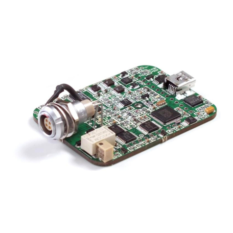
Innophase Talaria TWO Installation manual

Copyright ©InnoPhase, Inc. 2017, All Rights Reserved
2 PROPRIETARY and CONFIDENTIAL
Subject to Change Without Notice
InnoPhase, Inc.
6815 Flanders Drive
San Diego, CA 92121
innophaseinc.com
INP2045
Table of Contents
1. Introduction.................................................................................................................................................. 3
1.1 Package Contents ................................................................................................................................... 3
1.2 Pre-requisites.......................................................................................................................................... 3
1.3 ESD Precaution ...................................................................................................................................... 3
2. Talaria TWO Description and Operation..................................................................................................... 4
3. Talaria TWO Block Diagram....................................................................................................................... 5
4. Talaria TWO Maximum Transmit Power and Operating Temp .................................................................. 5
5. Talaria TWO Schematics ............................................................................................................................. 6
5.1 PCB Layout....................................................................................................................................... 7
5.2 FTDI Layout and Port Connections................................................................................................... 8
5.3 Talaria TWO Module Pinout.................................................................................................................. 8
5.4 Pin Description.................................................................................................................................. 9
6. Antenna ............................................................................................................................................................... 10
7. Power Supply ............................................................................................................................................. 10
8. Talaria TWO Module Integration in End Products.................................................................................... 10
9. FCC/ISED Regulatory Notices .................................................................................................................. 11
9.1 Modification statement......................................................................................................................... 11
9.2 Interference Statement.......................................................................................................................... 11
9.3 Radio Frequency Radiation Exposure Statement................................................................................. 11
9.4 RF Exposure Statement for Module Integration................................................................................... 11
9.5 Labeling Requirements for the Host Device ........................................................................................ 12
10. Disclaimers................................................................................................................................................. 13
11. Support Details........................................................................................................................................... 14
12. Abbreviations ............................................................................................................................................. 15
13. Revision History......................................................................................................................................... 15

Copyright ©InnoPhase, Inc. 2017, All Rights Reserved
3 PROPRIETARY and CONFIDENTIAL
Subject to Change Without Notice
InnoPhase, Inc.
6815 Flanders Drive
San Diego, CA 92121
innophaseinc.com
INP2045
1. Introduction
Welcome to Talaria TWO Hardware user guide. This guide provides quick steps to get started with the provided
Talaria TWO Module and SDK boards and allow basic Wi-Fi/BLE operations using the built-in Serial-to-Wi-Fi
application.
1.1 Package Contents
The package contains following items:
1. Talaria TWO INP2045 Module board mounted on SDK board
2. Micro USB cable
1.2 Pre-requisites
Following are pre-requisites for the quick start:
1. A Windows or Linux PC with one USB port to connect to Talaria TWO SDK board. A Linux PC is
generally recommended over Windows.
2. A COM port console application such as PuTTY.
3. Python (3.6+) software installed.
4. Openocd (latest) & ZADIG software tools installed.
1.3 ESD Precaution
This electronic device can be damaged by ESD. Innophase Inc., recommends that all bare
PCB and integrated circuits be handled with appropriate precautions. Failure to observe proper handling
procedures can cause damage.
ESD damage can range from subtle performance degradation to complete device failure. Precision integrated
circuits may be more susceptible to damage because very small parametric changes could cause the device
not to meet its published specifications.

Copyright ©InnoPhase, Inc. 2017, All Rights Reserved
4 PROPRIETARY and CONFIDENTIAL
Subject to Change Without Notice
InnoPhase, Inc.
6815 Flanders Drive
San Diego, CA 92121
innophaseinc.com
INP2045
2. Talaria TWO Description and Operation
Talaria TWO module is designed for low power IOT devices that need Wi-Fi and BLE connectivity. The SDK
board is a HW interface board developed for evaluation, SW development, and verification of Talaria module
product.
The Talaria TWO module (INP2045) is shown in Figure.4-1. It is a very small form factor PCB at 19mm x 20mm,
designed to be soldered down as a module on end product interface boards.
As shown in Figure 4-2, it is installed on a larger interface board (30mm x 65mm), known as the SDK board. This
assembly is designed to match the standard Raspberry Pi Zero form factor, including its 40 pin interface connector.
Figure 2-1 INP2045 Module
Figure 2-2 SDK Board with INP2045 module board installed
INP2045 module boards have all required components installed for standalone functionality. Edge connections
provide access to all GPIO pins, ADC_IN, En_Chip/Reset input and external 3.3V power input. The module also
contains an on-board printed antenna as well as RF shield (not shown in the Figure 4-2). The Talaria TWO module
schematic is provided in Figure 4-3.
The SDK board can be powered from an external 1.2-4.2 V battery through connector J10, or from USB through
Micro USB connector J7. Selection of input power supply source is commutated using connector J8.
Jumper J9 can be used to monitor INP2045 current consumption using an external current meter.

Copyright ©InnoPhase, Inc. 2017, All Rights Reserved
5 PROPRIETARY and CONFIDENTIAL
Subject to Change Without Notice
InnoPhase, Inc.
6815 Flanders Drive
San Diego, CA 92121
innophaseinc.com
INP2045
3. Talaria TWO Block Diagram
4. Talaria TWO Maximum Transmit Power and Operating Temp
Talaria TWO Operating Temperature: -100C to +750C
Mode
Maximum TX Power
Wi-Fi: DSSS, 1Mbps
18 dBm
Wi-Fi: CCK, 11 Mbps
18 dBm
Wi-Fi: OFDM, 54 Mbps
15 dBm
Wi-Fi: MCS7, 65 Mbps
12 dBm
BLE
10 dBm

Copyright ©InnoPhase, Inc. 2017, All Rights Reserved
6 PROPRIETARY and CONFIDENTIAL
Subject to Change Without Notice
InnoPhase, Inc.
6815 Flanders Drive
San Diego, CA 92121
innophaseinc.com
INP2045
5. Talaria TWO Schematics
Figure 5-3 INP2045 Module schematic.
For evaluation and SW development, the INP2045 Talaria TWO module is installed on an SDK board which
provides communication to an external PC though a standard USB interface.
An additional 40 pin connector on the SDK provides access to UART, JTAG and SPI communication with
peripheral devices as well as exposes all the INP2045 GPIO for development and integration of the application.
40 pin connector pinout is shown in Figure 5-4.

Copyright ©InnoPhase, Inc. 2017, All Rights Reserved
8 PROPRIETARY and CONFIDENTIAL
Subject to Change Without Notice
InnoPhase, Inc.
6815 Flanders Drive
San Diego, CA 92121
innophaseinc.com
INP2045
5.2 FTDI Layout and Port Connections
The Talaria TWO SDK board uses an FTDI 4232h quad high-speed USB multi-purpose serial device to interface
the TalariaTWO device to a host for evaluationand development. The FTDIdevice implementation is given below:
FTDI Bus
Interface to Talaria TWO
A
JTAG
B
SPI
C
UART
D
CONSOLE (UART)
Table 1: FTDI Bus Utilization
The port numbers A, B, C and D are assigned by the Windows OS based on which port on the PC is used. Note that
the order of COM ports is important and directly map to the FTDI layout. In this case COMc corresponds to UART
and COMd corresponds to CONSOLE. Note that if a different USB port is used, the port numbers will change.
5.3 Talaria TWO Module Pinout

Copyright ©InnoPhase, Inc. 2017, All Rights Reserved
9 PROPRIETARY and CONFIDENTIAL
Subject to Change Without Notice
InnoPhase, Inc.
6815 Flanders Drive
San Diego, CA 92121
innophaseinc.com
INP2045
5.4 Pin Description
PIN #
Name
Description
1
AGND
Ground connection
2
V_3.3V
Power Supply Input 2.7…4.0V
3
V_3.3V
Power Supply Input 2.7…4.0V
4
AGND
Ground connection
5
AGND
Ground connection
6
AGND
Ground connection
7
AGND
Ground connection
8
AGND
Ground connection
9
AGND
Ground connection
10
EN_CHIP
Chip Enable/_Reset or Shutdown Input
11
GPIO 14
GPIO Input/Output
12
GPIO 0
GPIO Input / Output
13
GPIO 1
GPIO Input / Output
14
GPIO 2
GPIO Input / Output
15
GPIO 3
GPIO Input / Output
16
GPIO 4
GPIO Input / Output
17
GPIO 5
GPIO Input / Output
18
VDDIO
Power Output. SW configurable
19
GPIO 17
GPIO Input / Output
20
GPIO 18
GPIO Input / Output
21
GPIO 19
GPIO Input / Output
22
GPIO 20
GPIO Input / Output
23
GPIO 21
GPIO Input / Output
24
AGND
Ground connection
25
ADC_IN
ADC Analog Input (voltage range is 0…1 V)
26
AGND
Ground connection

Copyright ©InnoPhase, Inc. 2017, All Rights Reserved
10 PROPRIETARY and CONFIDENTIAL
Subject to Change Without Notice
InnoPhase, Inc.
6815 Flanders Drive
San Diego, CA 92121
innophaseinc.com
INP2045
6. Antenna
Talaria TWO module has a proprietary integrated/printed antenna. It is a Double-sided Inverted F (IFA) antenna
and has been implemented as printed PCB elements.
By design and verification, Antenna does not require any additional matching component if the module is used as
standalone product.
Talaria TWO module’s antenna has omnidirectional radiating pattern and following performance specifications:
Max (Peak) Antenna Gain
0 dBi
Average Antenna Efficiency
-5.0 dB (31.4%)
7. Power Supply
Talaria TWO INP2045 module is designed to use external power supply. It utilizes internal power management
circuit including 2 high efficiency buck converters.
External power can be delivered from battery or a power supply connected to pins 2, 3 and AGND. Voltage from
power source should be between 2.7V to 4.0V.
8. Talaria TWO Module Integration in End Products
INP2045 Module is provided to customers with a reference interface board (SDK board) as an example of how the
module can be integrated with an end product.
For specific questions and support need to integrate Talaria TWO into customer platforms, customers are advised
to contact Innophase Inc. We provide comprehensive support for HW and SW source documentation, design
reviews, and verification.
Our corporate web site (www.innophaseinc.com) provided links to product briefs, applications, knowledge base
and client portal for personalized support to Innophase customers.
Customers can send also contact Innophase by mail for general queries (sales@innophaseinc.com).

Copyright ©InnoPhase, Inc. 2017, All Rights Reserved
11 PROPRIETARY and CONFIDENTIAL
Subject to Change Without Notice
InnoPhase, Inc.
6815 Flanders Drive
San Diego, CA 92121
innophaseinc.com
INP2045
9. FCC/ISED Regulatory Notices
9.1 Modification statement
Changes or modifications made to this equipment not expressly approved by Innophase Inc. may void the FCC
authorization to operate this equipment.
9.2 Interference Statement
This device complies with Part 15 of the FCC Rules and with Industry Canada license-exempt RSS standard(s).
Operation is subject to the following two conditions:
(1) this device may not cause harmful interference, and
(2) this device must accept any interference received, including interference that may cause undesired operation.
Le présent appareil est conforme aux CNR d'Industrie Canada applicables aux appareils radio exempts de licence.
L'exploitation est autorisée aux deux conditions suivantes:
(1) l'appareil ne doit pas produire de brouillage, et
(2) l'appareil doit accepter tout brouillage radioélectrique subi, même si le brouillage est susceptible d'en
compromettre le fonctionnement
9.3 Radio Frequency Radiation Exposure Statement
This device complies with FCC/IC radiation exposure limits set forth for an uncontrolled environment.
The device should be installed and operated with minimum distance of 20 CM between the device/antenna and all
persons. This device must not be co-located or operating in conjunction with any other antenna or transmitter
without further RF Exposure evaluation.
9.4 RF Exposure Statement for Module Integration
This module has been granted modular approval for mobile applications. Host products integrators may use the
module in their final products without additional FCC certification if they meet the followingconditions. Otherwise.
additional FCC approvals must be obtained.
•The host product with the module installed must be evaluated for simultaneous transmission requirements
•The user manual for the host product must clearly indicate the operating requirements and conditions that must
be observed to ensure compliance with current FCC IC RF exposure guidelines.

Copyright ©InnoPhase, Inc. 2017, All Rights Reserved
12 PROPRIETARY and CONFIDENTIAL
Subject to Change Without Notice
InnoPhase, Inc.
6815 Flanders Drive
San Diego, CA 92121
innophaseinc.com
INP2045
9.5 Labeling Requirements for the Host Device
The host device shall be properly labelled to identify the module within the host device. The certification label of
the module shall be clearly visible at all times when installed in the host device, otherwise the host device must be
labelled to display the FCC ID and IC of the module, preceded by the words "Contains transmitter module", or the
word "Contains", or similar wording expressing the same meaning, as follows:
Contains FCC ID: 2AVAL-INP2045
Contains IC: 25715-INP2045
L'équipement hôte doit être correctement étiqueté pour identifier les modules dans l'équipement. L'étiquette de
certification du module doit être clairement visible en tout temps lorsqu'il est installé dans l'hôte, l'équipement
hôte doit être étiqueté pour afficher le FCC ID et IC du module, précédé des mots "Contient le module émetteur",
ou le mot "Contient", ou un libellé similaire exprimant la même signification, comme suit:
•Contient FCC ID: 2AVAL-INP2045
•Contient IC: 25715-INP2045

Copyright ©InnoPhase, Inc. 2017, All Rights Reserved
13 PROPRIETARY and CONFIDENTIAL
Subject to Change Without Notice
InnoPhase, Inc.
6815 Flanders Drive
San Diego, CA 92121
innophaseinc.com
INP2045
10. Disclaimers
Limited warranty and liability —Information in this document is believed to be accurate and reliable. However,
InnoPhase Incorporated does not give any representations or warranties, expressed or implied, as to the accuracy or
completeness of such information and assumes no liability associated with the use of such information. InnoPhase
Incorporated takes no responsibility for the content in this document if provided by an information source outside of
InnoPhase Incorporated.
InnoPhase Incorporated disclaims liability for any indirect, incidental, punitive, special or consequential damages
associated with the use of this document, applications and any products associated with information in this
document, whether or not such damages are based on tort (including negligence), warranty, including warranty of
merchantability, warranty of fitness for a particular purpose, breach of contract or any other legal theory. Further,
InnoPhase Incorporated accepts no liability and makes no warranty, express or implied, for any assistance given with
respect to any applications described herein or customer product design, or the application or use by any customer’s
third-party customer(s).
Notwithstanding any damages that a customer might incur for any reason whatsoever, InnoPhase Incorporated’
aggregate and cumulative liability for the products described herein shall be limited in accordance with the Terms
and Conditions of identified in the commercial sale documentation for such InnoPhase Incorporated products.
Right to make changes —InnoPhase Incorporated reserves the right to make changes to information published in
this document, including, without limitation, changes to any specifications and product descriptions, at any time and
without notice. This document supersedes and replaces all information supplied prior to the publication hereof.
Suitability for use —InnoPhase Incorporated products are not designed, authorized or warranted to be suitable for
use in life support, life-critical or safety-critical systems or equipment, nor in applications where failure or malfunction
of an InnoPhase Incorporated product can reasonably be expected to result in personal injury, death or severe
property or environmental damage. InnoPhase Incorporated and its suppliers accept no liability for inclusion and/or
use of InnoPhase Incorporated products in such equipment or applications and such inclusion and/or use is at the
customer’s own risk.

Copyright ©InnoPhase, Inc. 2017, All Rights Reserved
14 PROPRIETARY and CONFIDENTIAL
Subject to Change Without Notice
InnoPhase, Inc.
6815 Flanders Drive
San Diego, CA 92121
innophaseinc.com
INP2045
11. Support Details
Sales Support:
To contact an InnoPhase Sales representative, email sales@innophaseinc.com
Technical Support:
Visit http://innophaseinc.com/technical-support/
•SDK is available for fast on-chip programming
•Open source tool chains based on GCC
•Innoscope proprietary debug development tool
Contact support@innophaseinc.com
Documentation
•Datasheet
•QuickStart Guide
•SDK User Guide
•API Reference Manual
•Power Measurement Guide
•HW User Guides
•Release Notes/Errata
Hardware Resources
•Reference Design (layout and design CAD files available)
•Software Development Platform
Coming soon:
•Knowledge Database
•Discussion Forums
•Customer Web Portal
InnoPhase has offices in US, Asia and Europe providing outstanding support for our customers.

Copyright ©InnoPhase, Inc. 2017, All Rights Reserved
15 PROPRIETARY and CONFIDENTIAL
Subject to Change Without Notice
InnoPhase, Inc.
6815 Flanders Drive
San Diego, CA 92121
innophaseinc.com
INP2045
12. Abbreviations
SPI
Serial Peripheral Interface
UART
Universal asynchronous receiver transmitter
13. Revision History
Date
Version
Release Notes
1/5/2020
0.4
FCC/IC Notices added
9/13/19
0.3
ESD Precaution added
9/13/19
0.2
Initial release
9/12/18
0.1
Initial Draft
This manual suits for next models
1
Table of contents
Other Innophase Control Unit manuals
Popular Control Unit manuals by other brands
ADLINK Technology
ADLINK Technology NuIPC cPCI-6760D Series manual
Felton
Felton Feltonmix U installation guide
Aumuller
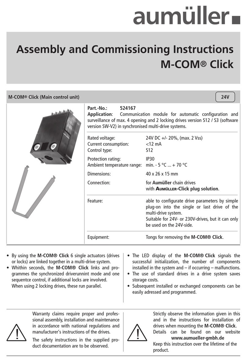
Aumuller M-COM Click Assembly and commissioning instructions

Cepex
Cepex EXTREME Series Installation and maintenance manual
Electronikbox
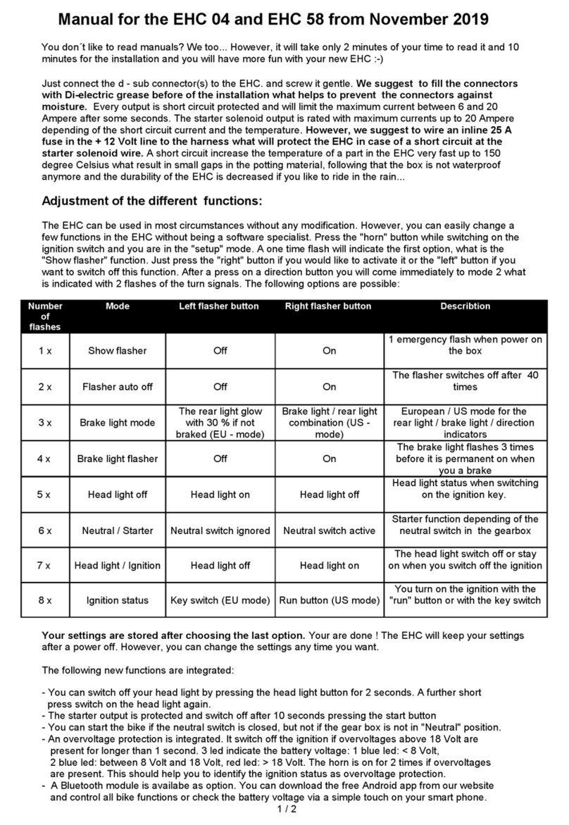
Electronikbox EHC 04 manual
Ebyte
Ebyte E43-900T13S3 user manual
M-system
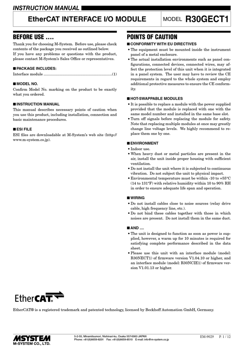
M-system EtherCAT R30GECT1 instruction manual
AXIOMTEK
AXIOMTEK FAB205-6P5 Series Quick installation guide
Mitsubishi Electric
Mitsubishi Electric CC-Link IE TSN user manual

Burkert
Burkert 2030 quick start

Robertshaw
Robertshaw 720 Series Installation data
Tews Technologies
Tews Technologies TCP872 user manual


