Innotech innTOUCH User manual

© MASS ELECTRONICS Pty Ltd 2011
Models:
ISS01 – innTOUCH Smart Sensor
ISS02 – innTOUCH Smart Sensor with Real Time Clock (RTC)
ISS03 – innTOUCH Smart Sensor with Universal Inputs (UI)
ISS04 – innTOUCH Smart Sensor with RTC and UI
Overview
The Innotech innTOUCH Smart Sensor is a wall mounted remote
Human Machine Interface (HMI) panel that provides a user interface
for supported Innotech MiniMAX, VAVMax, MicroMAX, Omni C20x and
Omni C40x controllers.
The innTOUCH Smart Sensor has a single communications channel,
with data transfer occurring through the power supply interface.
Power and communication are provided through the 2-way
Combicon connector.
One innTOUCH Smart Sensor can interface with a supported
controller. All data points on the innTOUCH Smart Sensor are
updated at the same rate as the controllers.
DS 13.05
October 2018
innTOUCH Smart Sensor
Applications
The innTOUCH Smart Sensor extends the capabilities of the
supported controllers. innTOUCH provides an easy to read visual
display of control values, and allows modifications to certain
parameters using the intuitive LCD and push button interface.
• Provides a HMI for the controller to which it is connected
• Immediate access for programming parameters
Features
• Icon based backlit Liquid Crystal Display (LCD)
• Modern, attractive enclosure design
• Four universal inputs (optional)
• One integrated thermistor input
• Real Time Clock (optional)
• Push button interface
• Direct interface with the MM01C, MM02C, VM01C, UM01C, OMC20,
OMC20D, OMC40 and OMC40D controllers
• Two wire single twisted pair, shielded or unshielded connection
from controller provides both comms and power
• Wall mounted device
Model designations
Thermistor Input Universal Inputs Real Time Clock
ISS01 — —
ISS02 —
ISS03 —
ISS04
Installation / Wiring
The innTOUCH Smart Sensor should be installed in an environment
that does not exceed the maximum operating parameters of the
device. It should be mounted in a clean and dry environment free of
vibration, and properly ventilated.
The cable providing both power and communication must be 2 core
shielded twisted pair cable. Polarity (+/–) MUST be observed when
connecting power.
The recommended cable length is maximum 30 metres. The cable
should not be run in parallel with conductors carrying high current.

© MASS ELECTRONICS Pty Ltd 2011
Page 2
DS 13.05 - ISS0x - innTOUCH Smart Sensor
October 2018
innTOUCH Parameters
The innTOUCH parameters can be accessed and programmed by
simultaneously pressing and holding the Power, Le Button, and
Right Button. You must use the Le Button button to exit and
return to the home screen in order to save any parameter changes to
memory. You can also modify multiple parameters before returning
to the home screen to save your changes.
Parameter 1: Sensor Calibration Value
The actual sensor temperature reading will be displayed. Use the Up
and Down buttons to enter an oset to the sensor reading.
P1 note: Only the integrated temperature sensor can be calibrated
from the wall unit. All other inputs can only be calibrated by the
configuration loaded on the controller.
Specifications
POWER SUPPLY REQUIREMENTS
Power input Powered by connected controller
This is a Safety Extra Low Voltage (SELV) of 5–12VDC. The power is
connected by the 2 way Combicon plug used for communications.
Polarity (+/–) MUST be observed when connecting power.
ENVIRONMENTAL
Operating Temperature 0 to 40°C non-condensing
Storage Temperature 0 to 50°C non-condensing
BATTERY - ISS02 & ISS04 Only
Contains Lithium Type Battery, Dispose of Properly.
(In accordance with local regulations).
Type CR-2032 Lithium
Nominal voltage 3 Volts
Shelf life 5 Years, depending on ambient
temperature
Caution: Risk of explosion if battery is replaced by an incorrect type.
ENCLOSURE
Designed to maximise airflow to the integrated thermistor. Can be
mounted with a standard vertical C-Clip, or in a standard wall enclosure.
Colour White/Grey
Dimensions (Maximum) (W)70mm x (H)121mm x (D)41mm
APPROVALS
EN61326-1:2013 for CE & RCM Labelling
Title 47 CFR, Part 15 Class A for FCC Marking
UL & C-UL listed to UL916, File Number E242628
INPUTS / OUTPUTS - ISS03 & ISS04 ONLY
4 physical inputs (optional) configured with soware as shown below:
Input Type Input Range Output Range
Dry Digital Input Open or Closed ON or OFF
Thermistor Input 96 k Ω – 677 Ω -20 ° C to 100°C
1 integrated thermistor input scalable for °F
Parameter 2: Default Set Point
The factory default set point is 22.5°C, or Fahrenheit equivalent.
P2 note: A compatible MAXIM controller will use the default value
stored in the Set Point Net Input block until innTOUCH has been
correctly detected and configured.
Parameter 3: Set Point Minimum Value
The minimum value for the set point. Factory default is 15°C or
Fahrenheit equivalent.
Parameter 4: Set Point Maximum Value
The maximum value for the set point. Factory default value is 30°C
or Fahrenheit equivalent.
Parameter 5: Set Primary Display Mode
This parameter determines what is displayed on the primary home
screen. The options are Temperature [Factory Default], Set Point
(SP), Auxiliary value (AVAL), Time or Date.
Parameter 6: Set Secondary Display Mode
This parameter determines what is displayed on the secondary
home screen (small field at the bottom of the screen). The options
are Temperature, Set Point (SP), Auxiliary value (AVAL), Time [Factory
Default] or Date.
Parameter 7: Set Temperature Display Units
Determines whether the temperature is displayed in Celsius [Factory
Default] or Fahrenheit.
P7 note: All temperature values will be processed using Celsius and
converted to Fahrenheit if P7 is set to display Fahrenheit.
Parameter 8: Set Primary Auxiliary Value Units
Determines how the Auxiliary value is displayed on the primary
display, if selected. The options are Temperature [Factory Default],
kW, kWh or nothing.
Parameter 9: Set Secondary Auxiliary Value Units
Determines how the Auxiliary value is displayed on the secondary
display, if selected. The options are Temperature, ppm, %, %Rh or
nothing [Factory Default].
Parameter 10: Minimum Scaling Factor for Auxiliary Value
This is the minimum scaling value for the Auxiliary Value output.
Factory default is -20.
Parameter 11: Maximum Scaling Factor for Auxiliary Value
This is the maximum scaling value for the Auxiliary Value output.
Factory default is 100.
Parameter 12: Fan Speed or AC Mode
This parameter sets the operating mode for innTOUCH.
• AHC When selected, the operator may change the
operating mode using the Right Button. Auto,
Heat, Cool or Vent can be selected.
• FAN Fan speed can be adjusted with the Le Button.
Auto, Heat, Cool and Vent mode is automatically
controlled.
• NONE Fan speed cannot be adjusted and Auto
operation is selected. The Le and Right
buttons are not used. [Factory Default]
The Factory Default parameters shown on this page are for the
latest default firmware. Please contact Innotech or your local
distributor for details on other Firmware Versions.

© MASS ELECTRONICS Pty Ltd 2011
Page 3
DS 13.05 - ISS0x - innTOUCH Smart Sensor
October 2018
innTOUCH Menu Structure
Below is the menu structure of the innTOUCH Smart Sensor.
OFF
ON
SET
Rhppm
kWh
%
Programming innTOUCH
Accessing the Programming Menu
With the device ON, from the default screen press and hold the
Centre Button for 3 seconds.
OFF
ON
SET
Rhppm
kWh
%
Adjust Time and Date
Press . Press .Adjust START day.
Press .
Adjust START month.
Press .
Adjust STOP month.
Press .
Go to Edit menu of
schedule.
Press .
Go to Delete menu
of schedule.
Press .
Adjust START time.
Press .
Adjust STOP time.
Press .
Select schedule.
Press .
Select schedule.
Press .
Adjust STOP day.
Press .
Edit as necessary.
Press .
Press .
Add Yearly Schedule
Add Weekly Schedule
Edit Schedules
Delete Schedules
Press from
CLOCK menu.
Adjust hour.
Press .
Adjust minutes.
Press .
Adjust DAY.
Press .
Adjust MONTH.
Press .
OFF
ON
SET
Rhppm
kWh
%
OFF MONTH
ON
Rhppm
kWh
%
STOP
OFF DAY MONTH
ON START
Rhppm
kWh
%
OFF DAY MONTH
ON
Rhppm
kWh
%
STOP
OFF MONTH
ON START
Rhppm
kWh
%
OFF MONTH
ON
Rhppm
kWh
%
STOP
Press . Press
twice.
Press Select On or O.
Press .
Adjust start
occurrence.
Press .
Adjust stop
occurrence. Press
.
Adjust start day.
Press .
Adjust stop day.
Press .
Adjust START
month. Press .
Adjust stop month.
Press .
Press .
Configure Daylight Savings Time (if supported)
Press . Press .Adjust day.
Press .
Adjust START hour.
Press .
Adjust START mins.
Press .
Adjust STOP hour.
Press .
Adjust STOP mins.
Press to save.
Select On or O.
Press to save.
•ThescheduleblockmustexistinMAXIMconfiguration.
•ThisfunctionisnotcompatiblewithOmni.
•ThescheduleblockmustexistinMAXIMconfiguration.
•ThisfunctionisnotcompatiblewithOmni.
•ThescheduleblockmustexistinMAXIMconfiguration.
•ThisfunctionisnotcompatiblewithOmni.
•ThescheduleblockmustexistinMAXIMconfiguration.
•ThisfunctionisnotcompatiblewithOmni.
Set Parameters
Year
Delete
Edit
Add
Information
Firmware
Model
Week
Edit
Copy
Add
Delete
DL Savings
Date
Time
Clock
OFF
ON
Rhppm
kWh
%
Press .
OFF
ON
SET
Rhppm
kWh
%
Press from
CLOCK menu.
Press and press
at date screen.
Adjust year.
Press .
© MASS ELECTRONICS Pty Ltd 2011
Page 4
DS 13.05 - ISS0x - innTOUCH Smart Sensor
October 2018
FCC Class A Notice
This device complies with Part 15 of the FCC Rules. Operation is subject to the following two conditions:
1. This device may not cause harmful interference.
2. This device must accept any interference received, including interference that may cause undesired operation.
Note – This equipment has been tested and found to comply with the limits for a Class A digital device, pursuant to Part 15 of the FCC Rules. These limits are designed to provide
reasonable protection against harmful interference when the equipment is operated in a commercial environment. This equipment generates, uses and can radiate radio frequency
energy and, if not installed and used in accordance with the instruction manual, may cause harmful interference to radio communications.
Operation of this equipment in a residential area is likely to cause harmful interference in which case the user will be required to correct the interference at their own expense.
Modifications to this device may void the authority granted to the user by the FCC to operate this equipment.
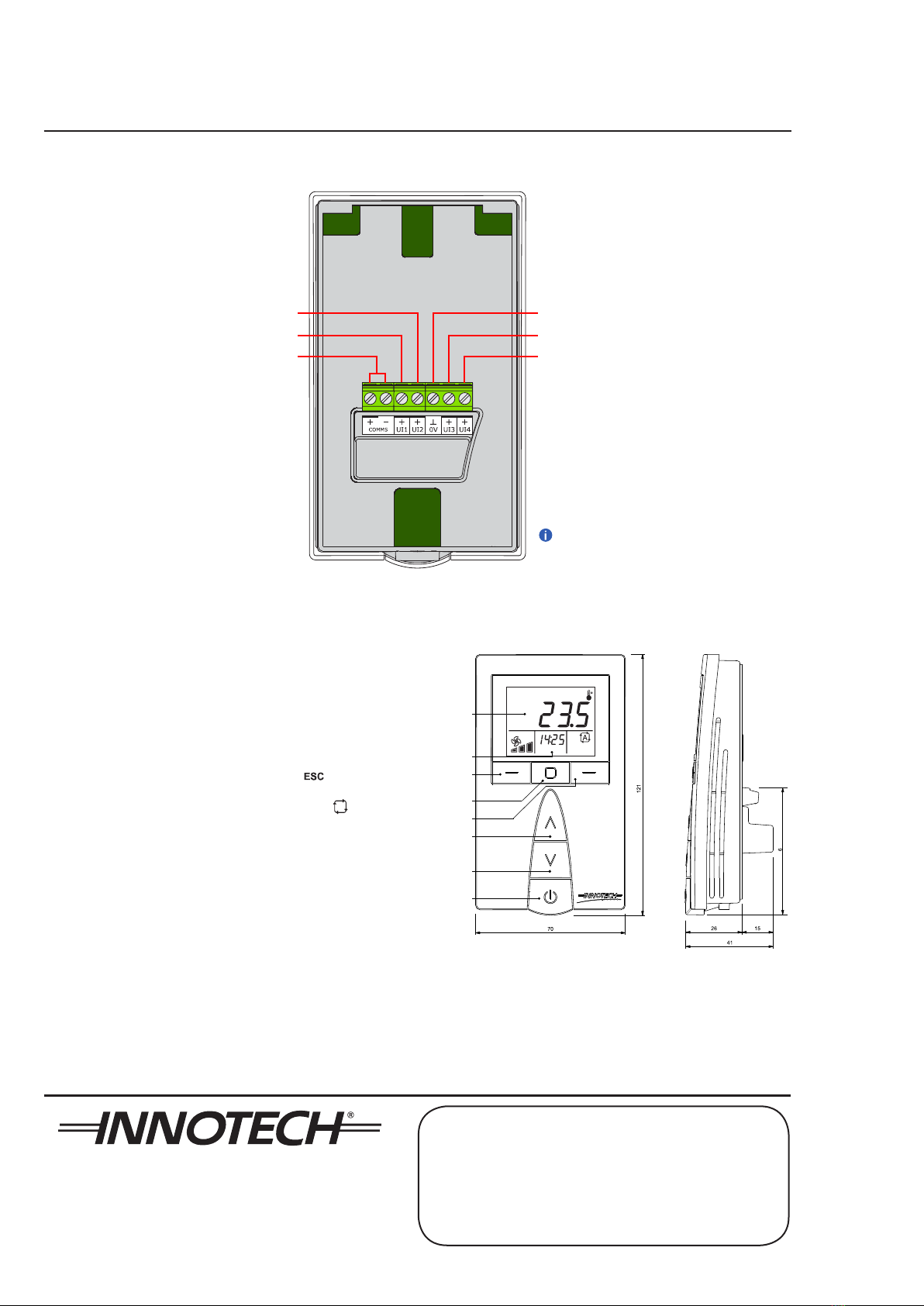
innTOUCH Smart Sensor Connection Diagram
Left Button
Centre Button
Right Button
Up
Down
Power ON/OFF
Primary Display
Secondary Display
1
innTOUCH Smart Sensor Parts Identification and Dimensions
Universal Input 2 (+) *
Universal Input 1 (+) * Universal Input 3 (+) *
Universal Input 4 (+) *
Input Ground 0V *
innTOUCH Comms
(Power + Comms)
*Only available on ISS03 & ISS04 models
The Universal Inputs are for
Thermistor and Digital Input only
Button description
Power ON / OFF – Turn innTOUCH ON or OFF
Up and Down – Increase or decrease to adjust a value
Le Button – Exit and return to previous menu ( )
Centre Button – Enter, Save, Copy, or Delete function
Right Button – Scroll through menus or parameters ( )
YOUR DISTRIBUTOR
Australian Owned, Designed & Manufactured
by Mass Electronics Brisbane
Phone: +61 7 3421 9100 Fax: +61 7 3421 9101
Email:
[email protected] www.innotech.com
INNOTECH and the INNOTECH logo are registered and unregistered trademarks of Mass Electronics Pty Ltd in Australia, the USA and other countries.
This manual suits for next models
4
Other Innotech Accessories manuals


