manuals.online logo
Brands
  1. Home
  2. •
  3. Brands
  4. •
  5. Hytronik
  6. •
  7. Accessories
  8. •
  9. Hytronik HEC7430 User manual

Hytronik HEC7430 User manual

INSTRUCTION MANUAL FOR INTEGRATED SENSORDIM LED DRIVER
DAYLIGHT MONITORING VERSION, MODEL NO.: HEC7430
Technical Specifications
Section 1 Wiring
PRODUCT TYPE:
OPERATING VOLTAGE:
HF SYSTEM:
TRANSMISSION POWER:
DETECTION ANGLE:
DETECTION RANGE:
TIME SETTING:
DAYLIGHT SENSOR:
STAND-BY PERIOD:
STAND-BY DIMMING LEVEL:
MOUNTING:
WORKING TEMPERATURE:
IP RATING:
Integrated sensorDIM LED driver
120-277VAC 50Hz/60Hz
5.8GHz CW radar
<0.2mW
30° ~ 150°
Max. 12 x 6m (DxH)
5s ~ 10 min (30s ~ 30min on RC)
5 ~ 50LUX, disable (2 ~ 50Lux, disable on RC)
VVaPLQ
10% ~ 30%
Indoors, ceiling & wall mounted
-20°C ~ +50°C
IP20
LED current selection
N
L
Antenna module
connector
Detection area
Hold-time
Stand-by dimming level
Stand-by period
Daylight threshold
LED -
LED +
SYNC
]
SYNC
PUSH
Extended antenna
Infrared remote receiver
Daylight sensor
Cable side entry
Cable back entry
This is a smart integration of microwave motion sensor and multiple current selection LED driver.
With the help of detached sensor antenna, it requires very little space on the LED panel and gives pre-selected constant current
to drive the LEDs to work based on movement detection.
Note: the high-frequency output of this sensor is < 0.2mW, approximately just 1‰ of the transmission power of a mobile
telephone.
Main body
Sensor antenna
Wiring Diagram-Push Wiring Diagram-Push + Sync
Stranded wire: 0.5~1.5mm2 American wire gauge: 16~20AWG Wire stripping length: 9~10mm
sync
sync
sync
sync
N
L
Push
L
N
Push
L
N
Push
L
N
Push
Max.10pcs
Buzzer
sync
sync
sync
sync
3rd Floor, block C, complex building, 155#, Bai'gang road south,
Bai'gang village, Xiao Jin Kou town, Huicheng district, Huizhou 516023
Tel:86-752-2772020 F:86-752-2777877
E: [email protected] W:www.hytronik.com
CHINA FACTORY
Room D, 10/f, Tower A, Billion Center, 1 wang Kwong Road,
Kowloon Bay, Kowloon, Hongkong
T: 00852-35197525 F: 00852-30116936
E: [email protected]
HYTRONIK INDUSTRIAL LIMITED
Section 2 Settings
Detection range can be tuned by selecting the combination on the DIP switches to fit precisely for each specific application.
Detection range
I – 100%
II – 75%
III – 50%
IV – Sensor OFF 50 %
75%
10 0 %
Sensor OFF
21
I
II
III
IV
This setting determines the time period the lamp will remain at 100% upon detection.
Note: the timer is reset upon each motion detection.
Hold-time
I – 5s
II – 30s
III – 3min
IV – 10min
5s
30s
3min
10min
43
I
II
III
IV
The daylight threshold can be set on the DIP switches suit to the particular application.
1RWH³V´PHDQVRQRIIFRQWURO³´PHDQVELOHYHOGLPPLQJFRQWUROIL[WXUHQHYHUVZLWFKRIILHWKHOLJKWUHPDLQVDWWKH
stand-by dimming level until motion is detected.)
Daylight sensor
I – Disable
II – 50Lux
III – 10Lux
IV – 5Lux
This is the time period setting to keep at the low light output level before it is completely switched off in the long absence of
people.
Stand-by period (corridor function)
I – 0s
II – 10s
III – 30min
,9±
This is the dimmed low light output level setting after the hold-time has expired.
Stand-by dimming level
I – 10%
II – 30%
65
50Lux
10Lux
5 Lux
Disable
I
II
III
IV
V
30%
10%
9
I
II
0s
10s
30min
8
7
I
II
III
IV +
Section 3 Sensor Antenna & RC Settings
Work with remote control
HRC-05.
Super-compact sensor
antenna, with optional
FDEOHHQWU\VLGHHQWU\
and back entry)
Model SAM5
Cable side entry
Infrared remote receiver
Daylight sensor
40.4 11.2
6.8
8.8
35.9
2.5
13
25.2
30.7
Cable back entry
Remote Control HRC-05
Permanent ON/OFF [ ]
1. Press button , to select permanent ON or permanent OFF mode.
2. 3UHVVEXWWRQWRUHVXPHDXWRPDWLFRSHUDWLRQ3OHDVHUHIHUWRH[SODQDWLRQEHORZ
3. The mode will change to AUTO Mode after power failure.
Auto Mode [ ]
Press button to in initiate automatic mode. The sensor starts working and all settings remain as before the light was switched ON/OFF.
RESET [ ]
Press button , all settings go back to the value of DIP switch settings.
Test 2s function [ ]
3UHVVEXWWRQWKHVHQVRUJRHVLQWRWHVWPRGHKROGWLPHV1%WKHVWDQGE\SHULRGDQGGD\OLJKWVHQVRUVHWWLQJVDUHGLVDEOHGLQWHVWPRGH
2.Press button to exit from this mode, and the sensor settings are changed accordingly.
Ambient daylight threshold [ ]
Press button , the latest surrounding lux value overwrites previous lux value learned, and is set as the daylight threshold. This feature enables the fixture
to function well in any environment.
1
2
3
234
button 1
button 2
button 3
8
3
10
4
11
button 8
button
10
Power output [ ]
Press button , the output shifts between 80% and 100%, for energy saving purposes.
5
button 5
Dim +/- [ ]
Press button to adjust the light brightness between 10%~100% during hold-time.“+” increases the light level, “-” will decrease the light level.
9
button 9
Lux disable [ ]
Press button , the built-in daylight sensor is disabled, the light will always operate upon detection regardless of ambient light level.
14
button
14
5
9
4
11
12
Stand-by dimming level
Detection range
ON/
OFF Auto Mode Reset
Power
80%
Test
2s
10% 20%
30s 1min
100%
30min10min5min
0s 10s 1min
30%
SC1 SC2
SC3
Scene mode
10min
50% 10%
30min
Hold-time
Stand-by period
5min
Lux
Disable
2Lux
10Lux
50Lux
Daylight Sensor
SC4
Power
100% +
-
Dim
M/A
3
1
2
7
8
6
10
13
14
15
HRC-05
Note: the buzzer beeps one time when RC
receives signal successfully
Detection range [ ]
Press buttons in zone to set detection range at 100% / 50% / 10%.
Hold time [ ]
Press buttons in zone to set hold time at 30s / 1min / 5min / 10min / 30min.
Stand-by period [ ]
3UHVVEXWWRQVLQ]RQHWRVHWWKHVWDQGE\SHULRGDWVVPLQPLQPLQ
1RWH³V´PHDQVRQRIIFRQWURO³” means bi-leve of dimming control, the light will never switch off.
LHWKHOLJKWUHPDLQVDWWKHVWDQGE\GLPPLQJOHYHOXQWLOPRWLRQLVGHWHFWHG
Stand-by dimming level [ ]
Press buttons in zone to set the stand-by dimming level at 10% / 20% / 30% .
Daylight sensor [ ]
Press buttons in zone to set daylight sensor at 2lux / 10lux / 50lux.
6
Press button ,the sensor goes to manual override or semi-auto function.
15
11
13
12
7
Manual override/ semi-auto [ ]
Note: The buzzer beeps twice if it is in manual override mode, and beeps once if shifts to semi-auto mode.
button
15
zone 6
zone
11
zone
12
zone
7
zone 13
Scene mode options [ ]
Note: the end-user can fine tune the settings by pressing buttons of detection range / hold time / stand-by period / stand-by dimming level
/daylight sensor , the last setting will over-write that feature of the pre-set scene.
611
13
12
7
zone 4
There are 4 scene modes built into the remote control for different applications:
Scene options Detection range Hold time Stand-by period Stand-by dimming leve Daylight sensor
SC1 100% 1min 10min 10% 2Lux
SC2 100% 5min 10min 10% 2Lux
SC3 100% 10min 30min 10% 10Lux
SC4 100% 10min + 10% 50Lux
8
Section 4 Functions
Maximum 10pcs HEC7430 can be connected in parallel by interconnecting the “SYNC” terminals of the units, no matter which one detects the
PRYHPHQWDOO+(&FRQQHFWHGLQWKHJURXSWXUQRQWKHOLJKWVDWWKHVDPHWLPHDVORQJDVQDWXUDOOLJKWLVEHORZGD\OLJKWWKUHVKROGDVLIWKHVHQVRU
DQWHQQDLVVKDUHGDQGH[WHQGHGVHHZLULQJGLDJUDP7KHGHWHFWLRQDUHDFDQEHZLGHO\HQODUJHGLQWKLVZD\1HYHUWKHOHVVRWKHUVHWWLQJVVXFKDVKROG
time, stand-by period, stand-by dimming level and daylight threshold on each individual sensor stays the same, not affected by the extended sensor.
4.1 Synchronization Function
This sensor maybe over-ridden by the end-users to switch on/off the lights manually, or adjust the maximum brightness during motion hold-time with the
push-switch. This makes the product more user-friendly and offers more options to fit for extra-ordinary demands.
6KRUWSXVKVRQRIIIXQFWLRQ
21ĺ2))WKHOLJKWWXUQVRIILPPHGLDWHO\DQGFDQQRWEHOLJKWHQIRUDFHUWDLQWLPHHTXDOVWRKROGWLPHSUHVHWHYHQWKHUHLVPRYHPHQWLVGHWHFWHG$IWHU
this period, the sensor goes back to auto sensor mode.
2))ĺ21WKHOLJKWWXUQVRQDQGJRHVWRDXWRVHQVRUPRGHHYHQZKHQDPELHQW/X[OHYHOH[FHHGVWKHGD\OLJKWWKUHVKROG
/RQJSXVK!VDGMXVWWKHPD[LPXPEULJKWQHVVEHWZHHQDQGGXULQJKROGWLPH
* If customers do not want to have this manual override function, we can just leave this “push” terminal alone, not connected to any wire.
1RWH,IWKHGHWHFWLRQDUHDLVVHWDW³6HQVRU2))´LWEHFRPHVDGLPPDEOH/('GULYHUZKLFKFDQEHGLPPHGaE\SXVKVZLWFK
4.3 Manual Override
SECTION 5 TROUBLE SHOOTING
MALFUNCTION CAUSE REMEDY CAUSE REMEDY
The light will not come on
The lamp is always on
The lamp will not work
despite movement Check detection area setting
The lamp is on without any
identifiable movement
Incorrect light-control setting selected
Continuous movement in the detection zone
The sensor is not mounted for reliably
detecting movement
Movement occurred, but not identified by the
VHQVRU0RYHPHQWEHKLQGZDOOPRYHPHQWRI
small object in immediate lamp vicinity etc.)
Rapid movements are being suppressed to
minimize malfunctioning or the detection
radius is too small.
Faulty lamp
No power supply
Adjust daylight threshold setting
Replace lamp
Check power to sensor
Check detection area setting
Securely mount enclosure
1. Reduce sensitivity.
2. Check the movement behind
walls to avoid facilities such as
water pipe, fan, which may
mis-trigger the sensor.
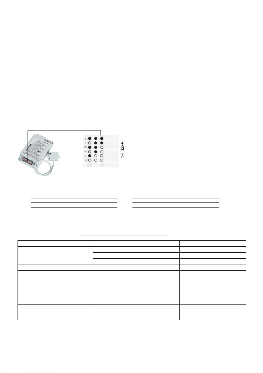
4.4 LED current selections
Current
350mA
500mA
550mA
700mA
750mA
900mA
123
The current can be easily configured by choosing the correct
FRPELQDWLRQRIWKH',3VZLWFKHVVHHWDEOHRQWKHOHIW
4.5 LED driver specifications
Input: 33W / 120~277V / 280~140mA
Output: a:P$
a:P$
a:P$#9a:P$#9
a:P$#9a:P$#9
a:P$#9a:P$#9
a:P$
a9P$
a9P$
a9P$#9a9P$#9
a9P$#9a9P$#9
a9P$#9a9P$#9
a9P$
4.2 Daylight Monitoring Function
Hytronik specially designed this function in software for deep energy-saving purpose. A built-in daylight sensor is designed to provide “smart photocell”
IXQFWLRQ7KLVIXQFWLRQFDQRQO\EHDFWLYDWHGZKHQVWDQGE\SHULRGLVVHWWR³´,QWKLVPRGHWKHODPSZLOODXWRPDWLFDOO\LOOXPLQDWHDWWKHGLPOHYHOVHWWLQJ
when the natural light goes below the threshold setting. The fixture will also switch off as the natural light returns.

Other Hytronik Accessories manuals

Hytronik HIM38/RF Quick guide

Hytronik

Hytronik HIM38/RF Quick guide

Hytronik HC005S/IR Quick guide

Hytronik

Hytronik HC005S/IR Quick guide

Hytronik HC428V/RF User manual

Hytronik

Hytronik HC428V/RF User manual

Hytronik HC019V User manual

Hytronik

Hytronik HC019V User manual

Hytronik HIR23/D2 Quick guide

Hytronik

Hytronik HIR23/D2 Quick guide

Hytronik HC419VRC/R User manual

Hytronik

Hytronik HC419VRC/R User manual

Hytronik HMW28/PRO Quick guide

Hytronik

Hytronik HMW28/PRO Quick guide

Hytronik DS05 Quick guide

Hytronik

Hytronik DS05 Quick guide

Hytronik HMW30 User manual

Hytronik

Hytronik HMW30 User manual

Hytronik HMW34 Quick guide

Hytronik

Hytronik HMW34 Quick guide

Hytronik HC438V User manual

Hytronik

Hytronik HC438V User manual

Hytronik HMW21 Quick guide

Hytronik

Hytronik HMW21 Quick guide

Hytronik HMW21 Quick guide

Hytronik

Hytronik HMW21 Quick guide

Hytronik HC019V/DH User manual

Hytronik

Hytronik HC019V/DH User manual

Hytronik HIR28 User manual

Hytronik

Hytronik HIR28 User manual

Hytronik HIR24 User manual

Hytronik

Hytronik HIR24 User manual

Hytronik HIM32 Quick guide

Hytronik

Hytronik HIM32 Quick guide

Hytronik HIR32 Quick guide

Hytronik

Hytronik HIR32 Quick guide

Hytronik HBIR30/CA Quick guide

Hytronik

Hytronik HBIR30/CA Quick guide

Hytronik HCD418 User manual

Hytronik

Hytronik HCD418 User manual

Hytronik HMW35 Quick guide

Hytronik

Hytronik HMW35 Quick guide

Hytronik HC005S/BT Quick guide

Hytronik

Hytronik HC005S/BT Quick guide

Hytronik HC028V/RF User manual

Hytronik

Hytronik HC028V/RF User manual

Hytronik HIR27 User manual

Hytronik

Hytronik HIR27 User manual

Popular Accessories manuals by other brands

Westone WBTV1 owner's manual

Westone

Westone WBTV1 owner's manual

abc Sun Control STOBAG CAMABOX BX4000 installation guide

abc Sun Control

abc Sun Control STOBAG CAMABOX BX4000 installation guide

Toa T-001T Specifications

Toa

Toa T-001T Specifications

daviteq A420-FCL user guide

daviteq

daviteq A420-FCL user guide

Lanaform Bora Bora instruction manual

Lanaform

Lanaform Bora Bora instruction manual

Lennox LGH420 installation instructions

Lennox

Lennox LGH420 installation instructions

Kasanova ADJH200A user manual

Kasanova

Kasanova ADJH200A user manual

FedEx SenseAware PT300D quick start guide

FedEx

FedEx SenseAware PT300D quick start guide

iNels RFDEL-71B-SL quick start guide

iNels

iNels RFDEL-71B-SL quick start guide

Met One Instruments 083E manual

Met One Instruments

Met One Instruments 083E manual

Philips CRP416 brochure

Philips

Philips CRP416 brochure

Westinghouse SR74FA02C-08 quick start guide

Westinghouse

Westinghouse SR74FA02C-08 quick start guide

LiCONiC StoreX STX40 operating manual

LiCONiC

LiCONiC StoreX STX40 operating manual

IFM MFH operating instructions

IFM

IFM MFH operating instructions

BRIGHT Coop Cage Unloading System Operator and  maintenance manual

BRIGHT Coop

BRIGHT Coop Cage Unloading System Operator and maintenance manual

Danby DKC054A1BSLDB user manual

Danby

Danby DKC054A1BSLDB user manual

BEA LZR SIGMA Original instructions

BEA

BEA LZR SIGMA Original instructions

Manitowoc K00133 installation instructions

Manitowoc

Manitowoc K00133 installation instructions

manuals.online logo
manuals.online logoBrands
  • About & Mission
  • Contact us
  • Privacy Policy
  • Terms and Conditions

Copyright 2025 Manuals.Online. All Rights Reserved.