Innotech TEMP User manual

© INNOTECH Arbeitsschutz GmbH. Irrtümer, Druckfehler, technische Änderungen vorbehalten!
© INNOTECH Arbeitsschutz GmbH. Errors and misprints accepted. We reserve the right to make technical changes.
DE – ACHTUNG: Die Verwendung des Innotech-Produktes ist erst zulässig nachdem
die Gebrauchsanleitung in der jeweiligen Landessprache gelesen wurde.
DE
EN – ATTENTION: Use of the Innotech product is only permitted after the instruction
manual has been read in the respective national language.
EN
IT – ATTENZIONE: L’utilizzo del prodotto Innotech è permesso solo previa lettura
del manuale di istruzioni nella lingua del paese corrispondente.
IT
FR – ATTENTION : L’utilisation du produit Innotech n’est autorisée qu’après
la lecture du mode d’emploi correspondant dans la langue du pays.
FR
NL – ATTENTIE: Het gebruik van dit Innotech product is pas toegestaan, nadat
degebruikshandleidingindetaalvanhetbetreendelandgelezenwerd.
NL
SV – O B S : Denna Innotech-produkt får inte användas, förrän bruksanvisningen
på respektive lands språk har lästs igenom.
SV
DK – GIV AGT: Det er først tilladt at anvende Innotech-produktet, før end brugsvej-
ledningen på det pågældende lands sprog er læst.
DK
ES – ATENCIÓN: El uso del producto Innotech sólo está permitido después de que
se hayan leído las instrucciones de uso en el idioma del respectivo país.
ES
PT – ATENÇÃO: O uso do produto Innotech apenas é permitido depois de ter lido as
instruções de uso na respectiva língua nacional.
PT
PL – UWAGA: korzystanie z produktu Innotech jest jedynie dozwolone po przeczy-
taniupodręcznikawjęzykunarodowym.
PL
RO – ATENŢIE:UtilizareaprodusuluiInnotechesteautorizatăabiadupăceaufost
cititeinstrucţiunileoriginaledeutilizareînlimbaţăriirespective.
RO
SL – POZOR: Uporaba izdelka Innotech je dovoljena šele po tem, ko navodila
preberete v svojem jeziku.
SL
CZ – POZOR:PrácesvýrobkemInnotechjepovolenaažpoprostudovánínávodu
kpoužitívpříslušnémjazycedanéhostátu.
CZ
SK – POZOR:PoužívanievýrobkuInnotechjepovolenéažpotom,keďstesi
prečítalinávodnaobsluhuvjazykupríslušnejkrajiny.
SK
HU – FIGYELEM: Az Innotech termékek használata csak az után engedélyezett,
miután saját nyelvén elolvasta a használati utasítást.
HU
TR - DİKKAT: INNOTECHürünününkullanımınaancakilgiliülkenindilindesunulmuş
olankullanımkılavuzununtamamenokunmasındanveanlaşılmasındansonraizinverilir.
TR
TEMP
Instruction manual

EN
2TEMP / 200122 / www.innotech.at
Prior to use, the following safety instructions and the current state of the art
must be taken into consideration.
-Keeptheseinstructionsforinstallationandusewiththeproductandcarefullyll
out the acceptance log, the test sheet and the test log.
- Completely read the instruction manual.
- Understand and accept the possibilities and restrictions of the protective equip-
ment as well as the risks associated with its use.
- TEMP should only be installed by specialised/competent experts familiar with
the safety system and in compliance with the current state of the art.
- You must be familiar with these instructions, as well as with the local safety
regulations as a prerequisite for installing and using the system. You must also
bephysicallyandmentallytandtrainedintheuseofPPE(PersonalProtective
Equipment).
-Medicalconditions(cardiovascularproblems,intakeofmedicines,alcohol)can
aectthesafetyoftheuserwhenworkinginhighplaces.
-Adheretotherespectiveaccidentpreventionregulations(e.g.workingonroofs)
wheninstalling/usingtherestraintsystem(andwhenascendingto,entering,
and descending from the roof).
-Measures(emergencyplan)mustbespeciedforfastrescuepriortoinstalling/
using the fall prevention system. Attention: after a fall, a longer period of suspen-
sion in personal protective equipment can cause severe injuries or even death
(suspensiontrauma).
- Before starting the work, you must ensure that no objects can fall to the ground
fromtheworksite.Theareabelowtheworksite(sidewalk,etc.)mustbekept
clear.
-Theinstallersmustensurethatthegroundissuitedforxingtheanchorage
device. If in doubt consult a structural engineer.
- If uncertainties arise during installation/use it is imperative that you contact
themanufacturer(www.innotech.at).
- Ensure that stainless steel does not come into any contact with swarf or steel
tools, as this may lead to corrosion.
- You should plan, install and use the restraint system in such a way that no one
can fall over the edge if the personal protective equipment is used properly.
(Seeplanningdocumentsatwww.innotech.at)
1SAFETY INSTRUCTIONS

EN
3
TEMP / 200122 / www.innotech.at
- When fastening the TEMP, always use a carabiner or INNOTECH travelling eye-
bolt and wear personal protective equipment in accordance with the information
contained in this instruction manual.
- For horizontal use, only those fasteners may be used that are suited for this
purposeandhavebeentestedfortherespectiveedges(sharpedges,sheetwith
trapezoidal corrugations, steel girder, concrete, etc.).
Attention: avoid pendulum fall!
- Fall arrest devices may only be used if approved for horizontal lifeline systems
by the manufacturers of these fall arrest devices.
- Make absolutely sure that the restraint system cannot be endangered by
sharp edges.
-Thereisahazardwhencombiningindividualelementsofthespeciedunits,since
the safe function of one of the elements can be impaired through the combination.
(Followthespecicinstructionsprovidedwitheachelement!)Incorrectapplica-
tions can result in severe or fatal injuries.
- After a fall and the resulting strain, you must stop using the restraint system and
haveitcheckedbyanexpert(componentparts,fasteningtothesubstrate,etc.).
- TEMP was developed for personal safety and may not be used for other purposes.
Neverattachundenedloadstotherestraintsystem.
- Do not use restraint systems if wind speeds exceed normal parameters.
- Do not make any changes to the approved anchorage device.
- If you provide the restraint system to external contractors, the familiarity with
theinstructionsforinstallationandusemustbeconrmedinwriting.
- Each person active in the areas where there is danger of falling is responsible for
ensuring that the connection to the anchorage system is kept as short as possible
to prevent the possibility of a fall.
A product that does no longer appear to be safe must no longer be used and
must be replaced immediately!
1SAFETY INSTRUCTIONS
EN
4TEMP / 200122 / www.innotech.at
PRIOR TO EACH USE THE USER MUST INSPECT:
- Before use, you must inspect the entire restraint system for obvious defects
(forinstance,reliableoperationofbucklesandratchets;loosescrews,deforma-
tion,abrasion,corrosion;beltsandseamsforweathering,fray,burnmarks,
chafe marks, cracks, cuts or other damage, etc.)
- The steel cable loops of the end locks: Ø = 220 mm
- Check the cable sag when the system is under tension.
(Re-tightenasnecessary:–seesection13“Tighteningthesystem”)
- In addition, use the acceptance log, test sheet and test log to verify that
the protective equipment is suitable for the application.
If there are any doubts concerning the reliable operation of the restraint system, it must
nolongerbeusedandcheckedbyanexpert(writtendocumentation).
ANNUAL INSPECTION: (=sections16/17)
- The complete safety device must be subjected to an inspection by a competent/
specialised expert who is familiar with the restraint system. Depending on the
intensity of use and environment it may be necessary to shorten the inspection
intervals. The inspection must be documented on the test sheet, which must be
stored along with the protective equipment.
ATTENTION! STOP USING THE EQUIPMENT IF:
- Damage or wear to its components is obvious.
- Stress has occurred due to falling.
- Defects have been detected during regular inspections.
- The service life has elapsed.
-Theproductidenticationisnolongerlegible.
Retire the equipment if a visual inspection performed by the owner or a competent/
specialisedexpertrevealeddecienciesorthePPEhasexpired.Whenyouretirethe
equipment, you can be certain that it will not be used again in future applications.
2INSPECTION/SERVICE LIFE
EN
5
TEMP / 200122 / www.innotech.at
The service life of the TEMP depends on the respective use and cannot be generally
denedduetodierentfrequenciesofuse,useconditions,careandstorage.
When used in compliance with the use guidelines and inspected annually by a competent/
specialised expert, the device has a service life of up to 10 years dating from the year
ofproduction(=markedontheharnessstrap).
Under normal use conditions there is a two year warranty on all components against
manufacturing defects. However, if the system is used in particularly corrosive atmos-
pheres, this period can be shortened.
Ifthereisstrain(afall)thewarrantyclaimisvoidforthosecomponentsthathavebeen
designed to absorb energy, or that may possibly be deformed and, therefore, must
be replaced. Attention: INNOTECH does not assume any warranty in case of improper
installation.
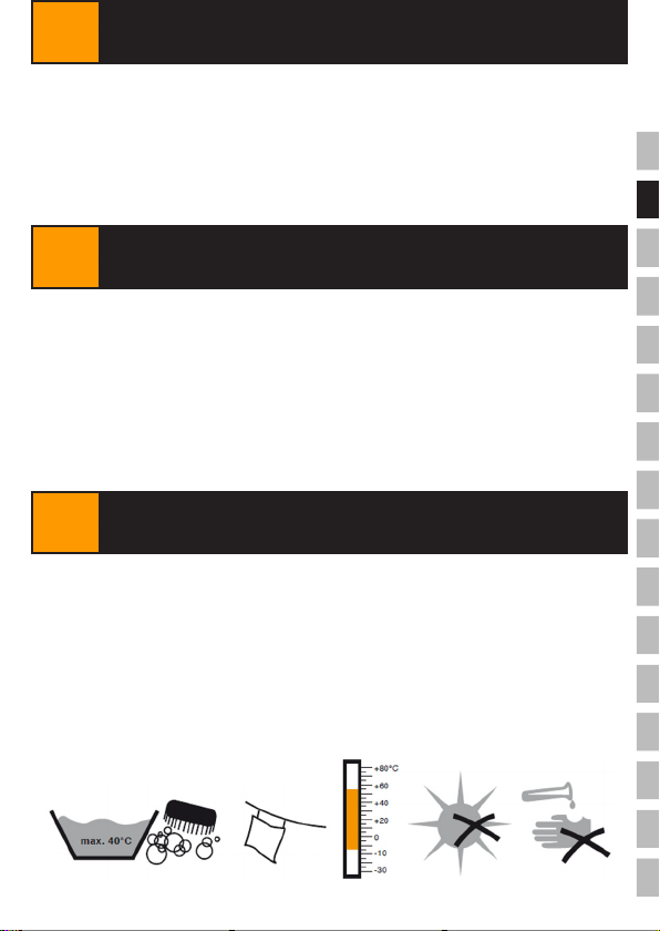
Store the restraint system in a suitable protective sheath to protect it from UV radiation,
chemicals,moisture,sourcesofheatandotherenvironmentalinuences.
IF NECESSARY:
Clean the harness strap using lukewarm water and mild soap, rinse it with clear water
andletitdryintheair(neverdryitinthelaundrydryeroraboveasourceofheat).
3SERVICE LIFE
4WARRANTY
5STORAGE/CARE

EN
6TEMP / 200122 / www.innotech.at
uENDS-10
uSZH-10
6DIMENSIONS/MATERIAL
-End lock ENDS-10:
anodised aluminium,
AISI 304 stainless steel,
galvanised steel
-Polyester harness strap:
50x4,000mmwithpowder-coatedsteelendtting
and protective polyester sleeve with smooth
PVC coating Ø 35 x 2,000 mm
-Ratchet:
50mm,18teeth,5,000daN;
composed of galvanised steel and plastic handle
-SZH-10 intermediate bracket:
AISI 304 stainless steel and nickel-plated steel
-Polyester harness strap:
50 x 2,500 mm
including sewn-in ratchet:
50mm,18teeth,5,000daN;
composed of galvanised steel and plastic handle
uAIO SEIL-30
-Stainless steel cable:
AISI316stainlesssteel,diameter:Ø8mm(7x7)
breakingload:37kN
33
51,4114,5
48
49,5
31,5
21
33
51,4114,5
48
49,5
31,5
21
33
51,4114,5
48
49,5
31,5
21
62
94
115
88
35
58,5
34
0,5
O
9
65
62
94
115
88
35
58,5
34
0,5
O
9
65
EN
7
TEMP / 200122 / www.innotech.at
7STANDARDS
8ANCHORAGE SUBSTRATE
9SIGNS & MARKINGS
INNOTECHTEMPhasbeentestedandcertiedinaccordancewith
EN 795:2012 TYPE B and EN 795:2012 TYPE C.
THE NOTIFIED AUTHORITY PARTICIPATING IN THE TYPE TEST:
DEKRATestingandCerticationGmbH,Dinnendahlstr.9,44809Bochum,C0158
ThetypetestwasperformedinaccordancewithEN795:2012.
It is best to install the horizontal lifeline system above the user.
The basic prerequisite is a static, carrying substructure.
The carrying structure used to fasten the TEMP must have great inherent stability
and a minimum strength of 22 kN.
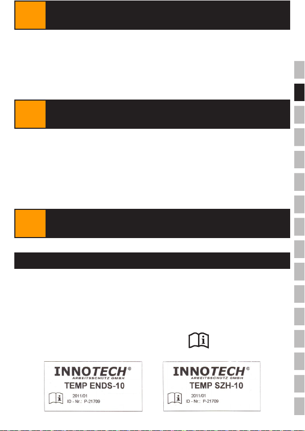
Name or logo of the manufacturer/reseller: INNOTECH
Type designation: TEMPENDS-10/TEMPSZH-10
Batch number of the reseller: 20xx/xx
Year of production: 20xx
Manufacturer’s ID no: P-xxxxx
Length: 4 m/2.5 m
Signs stating that the instructions specied
in the manual must be followed:
HARNESS STRAPS
Year of production
Length: 4 m
Year of production
Length: 2.5 m

EN
8TEMP / 200122 / www.innotech.at
EN 795:2012 TYP B
EN 795:2012 TYP C
TEMP-ENDS-10
13-03-10-Aufkleber-DE-A
SEILAUSLENKUNG MAX. 2,5
FALLDÄMPFER JA
0158
max.
JJJJ-..-...
Max. cable deection 2,5 m
Fall breaker YES
Name or logo of the manufacturer/reseller: INNOTECH
Type designation: TEMP
Numbers of the applicable standards: EN795:2012TYPEB
EN795:2012TYPEC
Maximum cable deection after a fall: 2.5 m
Fall breakers required: YES
DEKRA Testing and Certication GmbH:C0158
Year of manufacture and manufacturer’s serial number: 20xx - xx
Maximum number of people who will be secured: 4(including1personfor
rst-aidadministration)
Signs stating that the instructions specied
in the manual must be followed:
uEND LOCKS (= SYSTEM RATING PLATE)
The mobile horizontal lifeline system is suitable for temporary installation on various
base structures. Ideal for construction sites/building constructions of all kinds.
(Steel,facade,hallandbridgeconstruction,etc.)
Approved as a temporary horizontal lifeline system for 4 people(including1person
forrst-aidadministration)alongahorizontalandstraightspanwithapitch ranging
from 0° to a maximum of 15°.
SuitableforthefollowingfallprotectionsystemsinaccordancewithEN363:2008
• Restraint systems
• Workplace positioning systems
• Fall arrest systems
• Rescue systems
Safeapplicationrequiresthatyouobservethecorrespondingspecicationsprovided
by the PPE manufacturers.
For safety reasons, we recommend that you always use fall arrest systems as restraint
systems!TEMPisnotsuitableforabseilingwork(ropeaccesssystems(EN363:2008)).
9SIGNS & MARKINGS
10 USE INSTRUCTIONS

EN
9
TEMP / 200122 / www.innotech.at
Theusermustbecapableofselectingandproperlyhandlingthe“PersonalProtective
Equipment(PPE)againstfallsfromaheight”indueconsiderationofEN363:2008!
Theappropriate“PersonalProtectiveEquipment(PPE)againstfallsfromaheight”is
connected to the stainless steel cable of the TEMP anchorage device, which is spanned
horizontally,followingtheinstructionsofthePPE’smanufacturer(seeinstruction
manual for the PPE).
(E.g:EN353-2orEN354+EN355,etc.-->werecommendthatyouusea“Y”rope
or INNOTECH travelling eyebolt in connection with systems that include an intermediate
bracket.)
Attention!TheTEMPanchoragedeviceisttedwithshockabsorbersinordertoabsorb
theforcesgeneratedduringafall(harnessstraps+cableloopsoftheendlocks).Inthe
event of a fall, the stainless steel cable extends by contracting the cable loops, thereby,
absorbing the fall. This is why you need to make sure that, while using the fall arrest
system, you always leave enough free space below the user to prevent him from hitting
the ground in the event of a fall.
The minimum free space necessary between the fall point and the ground is
calculated as follows:
Free-fall height1(height of the unchecked fall until the PPE stops the fall)
+ Existingcablesagofthesystemafterinstallation
(checkduringuseandre-tightenasnecessary!)
+ Max.cabledeectionafterafallaccordingtotable(max.2.5m)
+ Manufacturer’sinstructionsofthePPEusedtopreventfallsfromaheight
(e.g.:max.brakingdistanceofthefallarrestdeviceasspeciedbythemanufacturer,etc.)
+ Shiftofthefall-arresteyeletattachedtothesafetyharnessinaccordancewithEN361
(approx.1.0m)
+ Safetymargin:1.0m
Length without intermediate bracket: Max.cabledeectionafterafall:(4people)
6m 1.1m
12m 1.7m
15m 2.0 m
20 m 2.5 m
1... can be avoided if positioned and used in the proper manner!
ThedeviceisattachedtothesystemonlybymeansoftheØ8mmstainlesssteelcablewhichisspanned
horizontally. Fastening the device to the harness strap, ratchet, etc. represents a safety risk and is prohibited!
INCORRECT APPLICATIONS
10 USE INSTRUCTIONS

EN
10 TEMP / 200122 / www.innotech.at
COMPONENTS TEMP SZH-10:
When storing the device, always secure the bolt at the end lock using the split pin!
COMPONENTS TEMP ENDS-10:
11 COMPONENTS
Table of contents
Other Innotech Accessories manuals


