6| LABNET MICROTUBE SHAKING INCUBATOR
The digits of the TEMP display may be reduced or increased by
pressing Temp or Temp respectively. The digits of the TIME
display may be reduced or increased by pressing Time or Time
respectively.
Press the above mentioned buttons for more than 3 seconds to set
up the exact value.
If the temperature should be set at 40°C and the time should be
set up at 60:00, then press the Temp and not release to see the
number reducing. When the number shows 40.0, release the
button, and it will be automatically saved in 3 seconds. Next
press the Time and not release to see the number reducing.
When the number shows 60:00, release the button, and it will be
automatically saved in 3 seconds.
Press Speed or Speed to set up for the speed. The number will
increase or reduce at a rate of 50 rpm, release the button when the
number reaches exact value, and it will be automatically saved in 3
seconds. When set up is done, press Start/Stop to start mixing.
After the setting value of temperature is saved successfully, the device
will automatically heat or cool, to achieve the setting temp. point.
8.3 Pulse vibration
Press Short/Prog to start instant vibration or short term vibration. Press the button to start it and release
the button to stop it. The running speed of pulse vibration is the highest vibration speed.
8.4 Correct temperature discrepancy
The temperature of the instrument has been calibrated before shipment. However, due to various
conditions, there might be discrepancy between the actual temperature and displayed temperature.
On such case, you may use the calibration button to correct the discrepancy.
To ensure the accuracy of the temperature, please wait for at least 30 minutes after the instrument
is set at a constant temperature, and then perform the calibration.
Please use certified standard class two mercury thermometers to calibrate this instrument.
Calibration point: Center hole of the module. Please fill the hole with paraffin oil and immerge
the thermometer bulb in it.
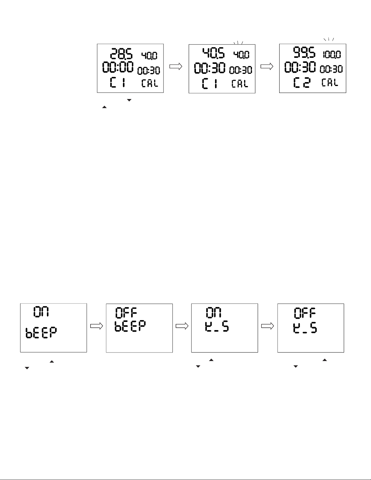
The method of the temperature calibration of this instrument is two-point linear calibration.
The calibration point may be set freely, and by setting the second calibration point the same as the
first calibration point, you can adjust the calibration point to one temperature point. For two-point
calibration, if set the two points at 40°C and 100°C, then other temperature points will be automatically
adjusted per the linear relationship of the two calibration points.
TEMP
TIME
TIME
TEMP
TIME
SPEED
TEMP
TIME
SPEED
TEMP
TIME
SPEED
TEMP
TEMP
TIME
TIME
TEMP
TIME
SPEED
TEMP
TIME
SPEED
TEMP
TIME
SPEED
TEMP
TEMP
TIME
TIME
TEMP
TIME
SPEED
TEMP
TIME
SPEED
TEMP
TIME
SPEED
TEMP
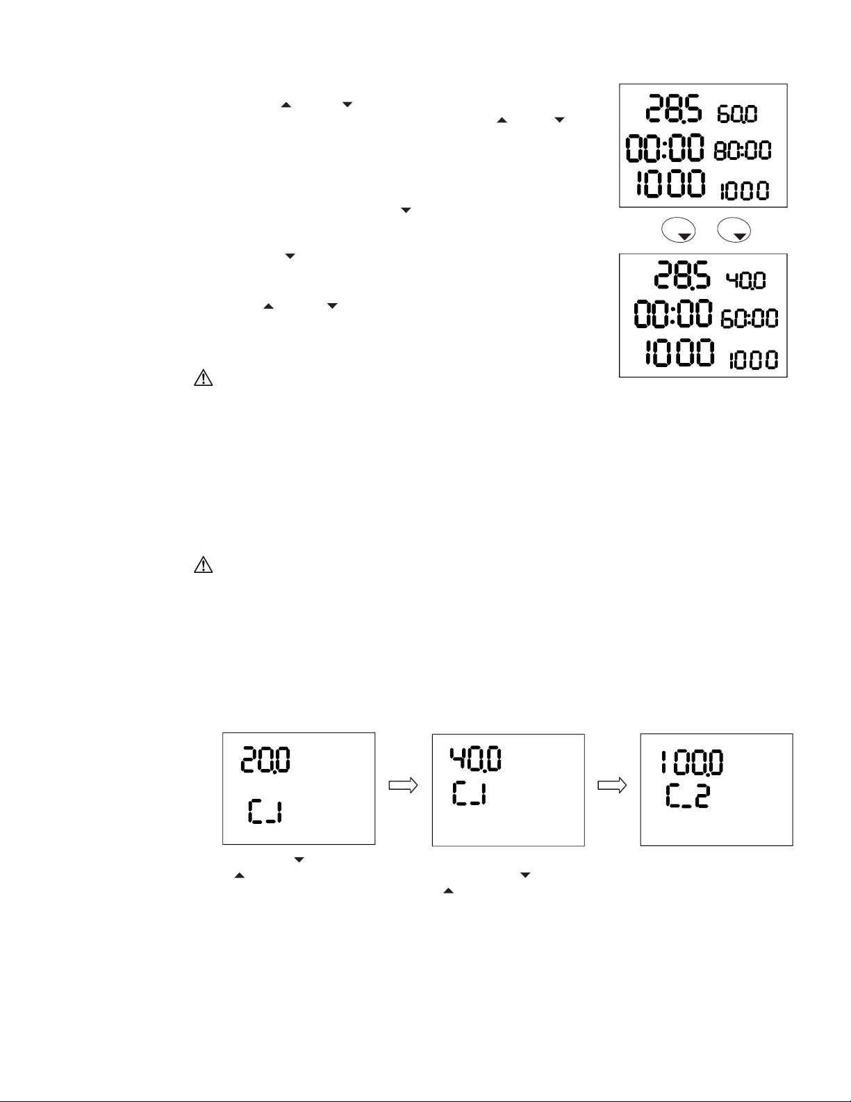
Press both Temp and
Temp at the same time,
and the display will show
the set up value of last
time (for example 20°C)
and the cursor of the first
calibration point, C_1.
Press the temperature
set up button Temp or
Temp to set up the first
calibration temperature
such as 40°C.
Perform the same
operation again to set up
the second calibration
temperature such as
100°C.
NOTE: When setting up the temperature points, an order of low temperature point first and high
temperature after is recommended. If on the case high temperature point is set first and low
temperature is set after, then when performing the following actual calibration, please follow the order
of low temperature first and high temperature after.
TEMP
TIME
TIME
TEMP
TIME
SPEED
TEMP
TIME
SPEED
TEMP
TIME
SPEED
TEMP
TIME
TIME
TEMP
TIME
SPEED
TEMP
TIME
SPEED
Temp
Time