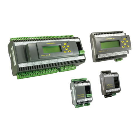
Innotech Omni Series User manual

Omni
INSTALLATION INSTRUCTIONS

Page 2 © Mass Electronics Pty Ltd 2017Edition 1.2 dated 08.08.2018
Proprietary
No part of this technical manual may be reproduced, transmitted, transcribed, stored in a retrieval
system, or translated into any language or computer language, in any form or by any means, without
prior written permission of Mass Electronics Pty Ltd.
Trademark
The term ‘Innotech’ used in this manual is a trademark of Mass Electronics Pty Ltd trading as
Innotech Control Systems Australia.
'Microso' and 'Windows' are registered trademarks of Microso Corporation in the United States
and other countries.
Disclaimer
While great eorts have been made to assure the accuracy and clarity of this document, Mass
Electronics Pty Ltd assumes no liability resulting from any omissions in this document, or from
misuse of the information obtained herein. The information in this document has been carefully
checked and is believed to be entirely reliable with all of the necessary information included. Mass
Electronics Pty Ltd reserves the right to make changes to any products described herein to improve
reliability, function, or design, and reserves the right to revise this document and make changes
from time to time in content hereof with no obligation to notify any persons of revisions or changes.
Mass Electronics Pty Ltd does not assume any liability arising out of the application or any use of any
product or circuit described herein; neither does it convey licence under its patent rights or the rights
of others.

Page 3 © Mass Electronics Pty Ltd 2017Edition 1.2 dated 08.08.2018
Document Management
Document Title:
Revision History
Omni Installation Instructions
Version
Number Date Summary of Changes
1.0 September 2017 Document first edition
1.1 March 2018 Update Omni U10 REM Images
1.2 August 2018 Specification update for supported U10 REMs on Omni C20
controllers

Page 4 © Mass Electronics Pty Ltd 2017Edition 1.2 dated 08.08.2018
This page has been le intentionally blank.

Page 5 © Mass Electronics Pty Ltd 2017Edition 1.2 dated 03.08.2018
Contents
Proprietary........................................................................................................................ 2
Trademark......................................................................................................................... 2
Disclaimer ......................................................................................................................... 2
Document Management................................................................................................... 3
Preliminary Information
1-1 Introduction ............................................................................................................. 12
1-1.1 Systems Covered by this Manual............................................................................12
1-1.2 Scope of this Technical Manual...............................................................................13
1-2 Specifications Table................................................................................................. 14
1-3 Special Considerations............................................................................................ 15
1-4 Installation Plans..................................................................................................... 15
1-5 Tools and Test Equipment....................................................................................... 15
Mechanical Installation
2-1 Introduction ............................................................................................................. 18
2-2 Physical Descriptions .............................................................................................. 18
2-2.1 Omni C40 Controller Dimensions & Identification.................................................19
2-2.2 Omni C20 Controller Dimensions & Identification.................................................21
2-2.3 Omni C14 Controller Dimensions & Identification.................................................23
2-2.4 Omni U10 Remote Expansion Module Dimensions & Identification.....................25
2-3 Expansion Bay.......................................................................................................... 26
2-3.1 Expansion Cards ......................................................................................................26
2-3.2 Backup Battery Replacement .................................................................................27
2-4 Installation Instructions .......................................................................................... 28
2-4.1 General Installation Instructions ............................................................................28
2-4.2 DIN Rails ...................................................................................................................28
2-5 HMI Installation........................................................................................................ 30
2-5.1 OMH01 Retrofit Onboard HMI .................................................................................30
2-5.2 OMH02 External USB HMI Display Module..............................................................30

Page 6 © Mass Electronics Pty Ltd 2017Edition 1.2 dated 03.08.2018
Electrical Installation
3-1 Introduction ............................................................................................................. 32
3-2 Electrical Installation Practices .............................................................................. 32
3-3 Programmable Point (UI/O) Specifications............................................................ 34
3-4 Digital Controller Wiring.......................................................................................... 36
3-4.1 Common Programmable Point Information..........................................................36
3-4.2 Omni C40/D Controller............................................................................................37
3-4.3 Omni C20/D Controller............................................................................................40
3-4.4 Omni C14/D Controller............................................................................................43
3-4.5 Omni U10 Remote Expansion Module....................................................................46
3-4.6 General Wiring Diagrams for Omni Controllers......................................................49
Networking
4-1 Overview.................................................................................................................. 54
4-2 Omni Products ......................................................................................................... 54
4-2.1 Definitions................................................................................................................55
4-3 Installation ............................................................................................................... 56
4-3.1 Network Specifications ...........................................................................................56
4-3.2 Cable Specifications - Ethernet...............................................................................56
4-3.3 Ethernet Considerations .........................................................................................57
4-3.4 Cable Specifications - RS-485..................................................................................57
4-3.5 Innotech Subsystem Wiring Considerations ..........................................................58
4-4 Cable Connection .................................................................................................... 60
4-4.1 Setting the IP and BACnet Instance via USB Connection ......................................60
4-4.2 Ethernet ...................................................................................................................62
4-4.3 RS-485 Wiring Topology ..........................................................................................67
4-4.4 Ethernet and RS-485................................................................................................70
4-4.5 Connection of Innotech Legacy Devices.................................................................70
Contents (Continued)

Page 7 © Mass Electronics Pty Ltd 2017Edition 1.2 dated 03.08.2018
List of Illustrations
Omni C40D Dimensions and Identification............................................................19
Omni C40D Dimensions (End View)........................................................................19
Omni OMH01 HMI....................................................................................................20
Expansion Bay (C20D Shown).................................................................................20
Ethernet Ports, MicroSD Card Slot and RS-485 Ports on side of Omni C40 ..........20
Omni C20D Dimensions and Identification............................................................21
Omni C20D Dimensions (End View)........................................................................21
Omni OMH01 HMI....................................................................................................22
Expansion Bay.........................................................................................................22
Ethernet Ports, MicroSD Card Slot and RS-485 Ports on side of Omni C20 ..........22
Omni C14D Dimensions and Identification............................................................23
Omni C14D Dimensions (End View)........................................................................23
Omni OMH01 HMI....................................................................................................24
Expansion Bay EOL Jumpers..................................................................................24
Ethernet Port, MicroSD Card Slot and RS-485 Ports on side of Omni C14............24
Omni U10 Dimensions and Identification..............................................................25
Omni U10 EOL Jumper Setting...............................................................................25
Expansion Bay Cover and Expansion Board ..........................................................26
Figure 2-1:
Figure 2-2:
Figure 2-3:
Figure 2-4:
Figure 2-5:
Figure 2-6:
Figure 2-7:
Figure 2-8:
Figure 2-9:
Figure 2-10:
Figure 2-11:
Figure 2-12:
Figure 2-13:
Figure 2-14:
Figure 2-15:
Figure 2-16:
Figure 2-17:
Figure 2-18:
Contents (Continued)
Commissioning
5-1 Introduction ............................................................................................................. 74
5-1.1 Inspect the Installation ...........................................................................................74
5-1.2 Check Input and Output Wiring ..............................................................................76
5-1.3 Check Ethernet Connections ..................................................................................80
5-1.4 Check RS-485 Connections .....................................................................................80
5-1.5 Check EOL Jumpers.................................................................................................81
5-1.6 Install Soware and Configure the Controller(s) ...................................................82
5-1.7 Initial Tests ..............................................................................................................86
5-1.8 Final System Check .................................................................................................88
Customer Assistance ...................................................................................................... 89
Innotech Support ..............................................................................................................89

Page 8 © Mass Electronics Pty Ltd 2017Edition 1.2 dated 03.08.2018
Battery Holder & Battery Orientation ....................................................................27
DIN Rail Dimensions................................................................................................28
DIN Rail Installation ................................................................................................29
Omni USB HMI Display ...........................................................................................30
Focus Generated Wiring Diagram Example ...........................................................36
Omni C40/D Input / Output Terminals ...................................................................37
Omni C40/D 24V Input Terminals ...........................................................................38
Omni C20/D Input / Output Terminals ...................................................................40
Omni C20/D 24V Input Terminals ...........................................................................41
Omni C14/D Input / Output Terminals ...................................................................43
Omni C14/D 24V Input Terminals ...........................................................................44
Omni U10 Input / Output Terminals.......................................................................46
Omni U10 24V Input Terminals...............................................................................47
U10 Connection to Omni ........................................................................................48
Omni C40 U10 Connection......................................................................................48
Omni Mounted on DIN Rail .....................................................................................49
Typical 0-10VDC Input to Omni...............................................................................49
Typical 0-10VDC Output from Omni .......................................................................49
Typical 4-20mA Input to Omni................................................................................50
Typical 4-20mA Output from Omni ........................................................................50
Typical Digital Input to Omni..................................................................................50
Typical Digital Output from Omni ..........................................................................50
Typical Two Wire 4-20mA Input to Omni................................................................51
Typical Thermistor Input to Omni..........................................................................51
Typical Digital Output from Omni using External DC Supply................................51
PTC Sensor Wiring Examples..................................................................................52
Connection from Computer to Omni via USB Mini-B ............................................60
Network Connections Window...............................................................................60
Login Screen Accessed Using USB..........................................................................61
BACnet and Ethernet Settings ................................................................................61
Example Controller Wiring Topology - Ethernet....................................................62
Example Controller Wiring Topology - Ethernet with switch................................63
Ethernet - TCP/IP Settings.......................................................................................64
Ethernet - Innotech TCP Settings ...........................................................................64
Protocols Settings - BACnet ...................................................................................65
Figure 2-19:
Figure 2-20:
Figure 2-21:
Figure 2-22:
Figure 3-1:
Figure 3-2:
Figure 3-3:
Figure 3-4:
Figure 3-5:
Figure 3-6:
Figure 3-7:
Figure 3-8:
Figure 3-9:
Figure 3-10:
Figure 3-11:
Figure 3-12:
Figure 3-13:
Figure 3-14:
Figure 3-15:
Figure 3-16:
Figure 3-17:
Figure 3-18:
Figure 3-19:
Figure 3-20:
Figure 3-21:
Figure 3-22:
Figure 4-1:
Figure 4-2:
Figure 4-3:
Figure 4-4:
Figure 4-5:
Figure 4-6:
Figure 4-7:
Figure 4-8:
Figure 4-9:
List of Illustrations (Continued)

Page 9 © Mass Electronics Pty Ltd 2017Edition 1.2 dated 03.08.2018
List of Illustrations (Continued)
Ethernet - BACnet IP Local - Device Settings..........................................................65
Ethernet - BACnet IP Public Settings......................................................................66
Example U10 Wiring Topology - RS-485 .................................................................67
RS-485 - Innotech Net Settings...............................................................................68
RS-485 - Innotech Global Settings..........................................................................68
RS-485 - BACnet MS/TP Settings.............................................................................69
RS-485 - Omni REM Settings ...................................................................................69
Example Controller Wiring Topology - Ethernet with U10s (RS-485)....................70
Example Controller Wiring Topology - Connection IG01 and Sub-Network.........70
Example Controller Wiring Topology - Connection of multiple devices...............71
Omni Power Terminals............................................................................................77
Checking Resistance ...............................................................................................77
Checking AC Power Input .......................................................................................78
Checking DC Power Input .......................................................................................78
Checking Digital Input Wiring.................................................................................80
End of Line Jumper, Typical Location ....................................................................81
IG01 and Sub-Network EOL Placement .................................................................81
Focus Activation Windows......................................................................................82
Start Menu and Omni REM Addresser ....................................................................83
Omni REM Addresser - REM Detected.....................................................................84
Omni REM Addresser - Configured .........................................................................84
Omni REM Upgrade Required.................................................................................85
Omni REM Upgrade Window...................................................................................85
Omni REM Upgrade Complete................................................................................85
Figure 4-10:
Figure 4-11:
Figure 4-12:
Figure 4-13:
Figure 4-14:
Figure 4-15:
Figure 4-16:
Figure 4-17:
Figure 4-18:
Figure 4-19:
Figure 5-1:
Figure 5-2:
Figure 5-3:
Figure 5-4:
Figure 5-5:
Figure 5-6:
Figure 5-7:
Figure 5-8:
Figure 5-9:
Figure 5-10:
Figure 5-11:
Figure 5-12:
Figure 5-13:
Figure 5-14:

Page 10 © Mass Electronics Pty Ltd 2017Edition 1.2 dated 03.08.2018
List of Tables
Manual Scope..........................................................................................................13
Specifications Table................................................................................................14
Nominal Resistance for Wire Sizes at 20°C.............................................................33
Programmable Point Specifications ......................................................................34
Recommended Wiring - C40 ...................................................................................38
Recommended Wiring - C20 ...................................................................................41
Omni C14/D 24V Input Recommended Wiring - C14..............................................44
Omni U10 24V Input ................................................................................................47
Ethernet Standards.................................................................................................56
Omni System Power Inputs ....................................................................................76
Table 1-1:
Table 1-2:
Table 3-1:
Table 3-2:
Table 3-3:
Table 3-4:
Table 3-5:
Table 3-6:
Table 4-1:
Table 5-1:

Omni
INSTALLATION INSTRUCTIONS
Preliminary Information
1

Omni Installation Instructions
Page 12 © Mass Electronics Pty Ltd 2017Edition 1.2 dated 16.08.2018
1-1 Introduction
This manual is intended to provide qualified technical personnel with complete and easy-to-follow
instructions for the installation and commissioning of the Innotech Omni BEMS controller and
associated devices.
Although the intent of this manual is to simplify the installation task, instructions contained in this
manual are based on the assumption that installation of an Innotech Omni Control System will be
accomplished by technically qualified personnel. Also, these instructions assume that installation
personnel are familiar with local regulations, codes and safety requirements.
Installers should familiarise themselves with the content of this manual before attempting
installation of the Omni Controller or associated devices in the Omni family.
Throughout this manual there are icons to illustrate notes and points of caution, as illustrated below:
These notices contain critical information, which MUST be read. Ignoring instructions in these notices could result in
damage to person or controller.
CAUTION
These notices contain information about the soware that must be done before proceeding further to ensure
success.
IMPORTANT
These notices indicate a piece of useful information which should be read.
1-1.1 Systems Covered by this Manual
Systems are intended for use in a variety of applications, the systems are designed on a modular
basis. This flexible system provides the most economical and eicient means of adapting the system
to the customer’s specific requirements.
The manual covers the Omni System. This system is based on one or more controllers as the major
control units interconnected with several ancillary units. These major control units included in this
manual are:
•Omni Controller (all models)
•Omni U10 Remote Expansion Module
For purposes of explanation, a System is defined as one or more controller units interconnected with
various ancillary units for the purpose of performing specific functions. An Omni system consists of
one or more Omni Controllers as the major control unit(s).
The purpose of this manual is to provide clear and complete instructions for all phases of the
installation of the devices that comprise your Omni System. In order to provide the clearest
instructions possible with minimum confusion, instructions in this manual are based on the following
approach:
•For simplicity of explanation, installation instructions in this manual are based on an Omni System
containing a single Omni Controller.
•Basic electrical wiring information is provided in the Electrical Installation chapter, and wiring
instructions for network systems are contained in the Network Installation chapter.

Page 13
Omni Installation Instructions
© Mass Electronics Pty Ltd 2017Chapter 1 – Preliminary Information
Table 1-1: Manual Scope
1-1.2 Scope of this Technical Manual
This technical manual contains:
Chapter Description
Chapter 1 -
Preliminary Information
Contains installation related information of a general nature such as
general safety considerations and pre-installation requirements.
Chapter 2 -
Mechanical Installation
Contains instructions and related data to facilitate the mechanical
installation of components of the Omni System. It also includes
information such as physical descriptions of the units, mounting
dimensions and mechanical installation guidelines.
Chapter 3 -
Electrical Installation
Contains electrical wiring information useful for installation of a basic
“standalone” system. Chapter 3 is augmented by network wiring
information in Chapter 4 - Network Installation. Appropriate references
are provided between Chapter 3 and Chapter 4 for installation of
network wiring.
Chapter 4 -
Network Installation
Provides detailed information for interconnecting various units in a
network configuration. The two electrical installation areas: Chapter 3
and Chapter 4 are purposely separated from each other in the interest
of clarity and to simplify the use of this manual.
Chapter 5 -
Commissioning
Provides instructions for post-installation inspection and checking of
the Omni System, power application and initial setup of the various
units that comprise the system.
References made throughout this manual to "Omni", "Controller" or "BEMS Controller" refer to all models of the
Omni BEMS Controller except where specified.
All references made throughout this manual to controller model numbers (C40, C40D etc) refer to models with and
without displays except where specified.
References made throughout this manual to "U10", "Omni U10" or "Omni REM" refer to the Omni U10 Remote
Expansion Module.

Omni Installation Instructions
Page 14 © Mass Electronics Pty Ltd 2017Edition 1.2 dated 16.08.2018
1-2 Specifications Table
Specification Omni C40 Omni C20 Omni C14 Omni U10
Processor Speed 800MHz 800MHz 600MHz 72MHz
Programmable Points (UI/O) 40 20 14 10
Non Volatile Memory 128KB 128KB 8KB -
Real-time Clock Yes Yes Yes -
RS-485 Ports 3 3 2 1
Ethernet - 100BASE-T 2 2 1 -
8GB MicroSD for Logging (32GB max.) Yes Yes Yes -
HMI (on-board) Optional Optional Optional -
HMI (External) Optional Optional - -
USB-A (Host) Yes Yes - -
USB-Mini B (PC Link) Yes Yes Yes Yes
PC Link Speed 480Mbps 480Mbps 480Mbps 12Mbps
ISS RS-485 Comms Yes Yes - -
Status LED Yes Yes Yes Yes
Field Supply 24VDC Yes Yes - -
Expansion Port Yes Yes - -
UI/O Point Processing Limit 90 70 14 N/A
Omni U10 Support (Total Devices) 5 5 - -
Web Server Yes Yes Yes -
Protocol Routing Yes Yes Yes -
BACnet Broadcast Management Device Yes Yes Yes -
Max. UI/O Power 0.5W 0.5W 0.5W 0.5W
Max. IO System Power 18W 10W 4.5W 4.5W
Table 1-2: Specifications Table
• The real-time clock battery is user replaceable but should only be replaced by qualified Innotech service
technicians or distributors. The battery is located in the expansion bay on all controller models.
• The controller's MicroSD card also contains PDF documents. For the latest documents, visit www.innotech.com.au.
• The optional on-board HMI module can only be installed by qualified Innotech service technicians.
• Omni U10 Remote Expansion Modules add 10 points for each U10 used.
Eg: An Omni C40 with 5 U10's will support 90 points total (40 [C40] + 50 [5 x U10's]).
• Not all controllers support the U10, see the table above for support and device limits.

Page 15
Omni Installation Instructions
© Mass Electronics Pty Ltd 2017Chapter 1 – Preliminary Information
1-3 Special Considerations
The following precautions and installation considerations must be observed to ensure personal
safety and to prevent damage to equipment:
•Local safety regulations, building codes and ordinances must be complied with during
installation. In cases of conflict with procedures in this manual, contact Innotech or its authorised
representative for clarification.
•To prevent damage to equipment, avoid applying electrical power to the equipment prior to
checking the system, unless specifically instructed to do so in this manual.
•The Omni System can be installed using common tools and test equipment. Only qualified
personnel familiar with local codes and practices should install the system. Wiring should only be
performed by someone knowledgeable of electronics and wiring installation practices. Refer to the
appropriate documentation when installing items provided by other manufacturers.
1-4 Installation Plans
The following installation items should be gathered and made available to the installation team:
•This technical manual.
•Computer-Generated Wiring Diagram: the Innotech Focus soware can be used to print a wiring
diagram for the specific application.
•For non-Innotech equipment, gather the manufacturer’s installation-related data such as
schematics, wiring diagrams, dimension diagrams, etc.
•Any other data source as it becomes known.
1-5 Tools and Test Equipment
A 2mm flat blade screwdriver is required for wiring of the terminals. A high impedance digital
Multimeter is the only item of electronic test equipment required.
Specification Omni C40 Omni C20 Omni C14 Omni U10
Processor Speed 800MHz 800MHz 600MHz 72MHz
Programmable Points (UI/O) 40 20 14 10
Non Volatile Memory 128KB 128KB 8KB -
Real-time Clock Yes Yes Yes -
RS-485 Ports 3 3 2 1
Ethernet - 100BASE-T 2 2 1 -
8GB MicroSD for Logging (32GB max.) Yes Yes Yes -
HMI (on-board) Optional Optional Optional -
HMI (External) Optional Optional - -
USB-A (Host) Yes Yes - -
USB-Mini B (PC Link) Yes Yes Yes Yes
PC Link Speed 480Mbps 480Mbps 480Mbps 12Mbps
ISS RS-485 Comms Yes Yes - -
Status LED Yes Yes Yes Yes
Field Supply 24VDC Yes Yes - -
Expansion Port Yes Yes - -
UI/O Point Processing Limit 90 70 14 N/A
Omni U10 Support (Total Devices) 5 5 - -
Web Server Yes Yes Yes -
Protocol Routing Yes Yes Yes -
BACnet Broadcast Management Device Yes Yes Yes -
Max. UI/O Power 0.5W 0.5W 0.5W 0.5W
Max. IO System Power 18W 10W 4.5W 4.5W

Omni Installation Instructions
Page 16 © Mass Electronics Pty Ltd 2017Edition 1.2 dated 16.08.2018
This page has been le intentionally blank.

Omni
INSTALLATION INSTRUCTIONS
Mechanical Installation
2

Omni Installation Instructions
Page 18 © Mass Electronics Pty Ltd 2017Edition 1.2 dated 03.08.2018
2-1 Introduction
This section of the manual contains instructions and related data to facilitate the installation of
components of the Omni System.
It is recommended that the main units of the Omni System, such as the Omni Controllers and it's
extended family of devices be mounted in steel cabinets to minimise the eects of electromagnetic
interference.
The flexibility of the Omni controllers and associated devices allows them to be installed in a wide
variety of configurations depending on the user’s preference. For this reason it is not possible to
include all the various installation configurations in this manual. Instead, this manual provides
examples of installations that are considered typical.
Innotech recognises that the installation examples described in this manual may not meet the user’s
requirements. However, information in this document should be used as a guide for all installations,
regardless of whether the specific circumstances match the examples given. In all cases, installation
personnel should familiarise themselves with the information contained in this section.
2-2 Physical Descriptions
The following paragraphs contain physical descriptions, including dimensions and installation-
related information, for the main devices of the Omni System. These paragraphs are intended to
provide the installer with suicient information to permit proper installation of the various units.
For devices not included in the following paragraphs, refer to the appropriate product datasheet.
Controllers are the main processing units that provide overall control of the Omni system. Controllers
are housed in a rectangular case made from flame retardant polycarbonate / ABS plastic listed under
UL94-V0. The types of controller units included in this manual are:
•Omni C40/D
•Omni C20/D
•Omni C14/D
•Omni U10 Remote Expansion Module
It is highly recommended that the Omni Series Controllers and peripheral devices be installed and mounted in a
steel enclosure to minimise the eect of Electro Magnetic Interference (EMI).

Page 19
Omni Installation Instructions
© Mass Electronics Pty Ltd 2017Chapter 2 – Mechanical Installation
2-2.1 Omni C40 Controller Dimensions & Identification
The Omni C40 & C40D Controllers are the largest controllers in the Omni controller range. The
controller features 40 programmable points, 3 RS-485 comms inputs, 2 RJ45 ethernet ports, USB A
and Mini-B connections and an ISS RS-485 input.
Optional HMI shown in the C40D image.
87.90mm (3.46”)
93.40mm (3.68”)
80mm (3.15”)
Figure 2-2: Omni C40D Dimensions (End View)
280mm (11.02”)
113.44mm (4.47”)
Programmable
Points
Programmable
Points Ethernet
(on side)
USB A
USB Mini-B
ISS
Input
24V
Out
24V
In Comms
Input
Optional HMI
Heartbeat LED
Figure 2-1: Omni C40D Dimensions and Identification
The Expansion
Bay contains EOL
Jumpers, backup
Battery and
Expansion port.
Comms
Indicators

Omni Installation Instructions
Page 20 © Mass Electronics Pty Ltd 2017Edition 1.2 dated 03.08.2018
Figure 2-3: Omni OMH01 HMI
LCD Screen
Watches
Alarms
Back Button
Warning / Alarm LEDs
Navigation Wheel
Figure 2-4: Expansion Bay (C20D Shown)
EOL Jumper RS485 Port 3 (Set)
Backup Battery
Expansion Slot
EOL Jumper RS485 Port 2 (Not Set)
EOL Jumper RS485 Port 1 (Not Set)
Figure 2-5: Ethernet Ports, MicroSD Card Slot and RS-485 Ports on side of Omni C40
This manual suits for next models
4
Table of contents
Other Innotech Controllers manuals
