BEC
170-450 Multi
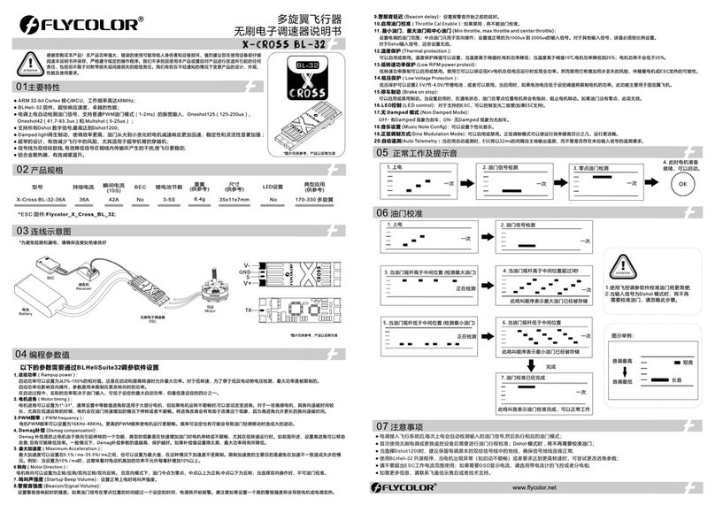
● .ARM 32-bi t Corte x M CU, freq uency up to 48 M H Z
● BL H eli_32 firmwa re,whic h is designed f or supe rior functi onali ty and performance .
● Supports regular 1-2ms pulse width input, a s well as Oneshot125 (125-250us), Oneshot42 (41.7 -83.3us) and
Multshot (5- 25us). The input signal is automatically detected by the E S C upon power up.
● Dshot signal is supported at any rate up to at least Dshot1200.
● Damped light does regenerative braking, c ausing very fast motor retardation, and inherentl y also does active
freewheeling.
● Supports higher K V motor and more power load, more suitab le for violent flight of racing drone .
● The silicone twisted-pair of the throttle signal cable effectively reduces the crosstalk caused by signal
transmission, and ma kes flight more stable.
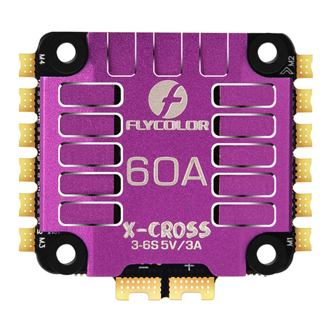
● Aluminum heat sink effectively slow down the t emperature rise(45A/50A).Supports the RG B tricolor setting
(35A only) to make the fligh t more colorful.
Thank you for using our product. Any Improper operation may cause personal injury or damage to the
product and related equipments. This high power system for R C model can be dangerous ,we strongly
recommend reading the user manual carefully and completely. We will not assume any responsibility for any
losses caused by unauthorized modifications to our product. We have the right to change the design,
appearance, performance and usage requirements of the product unannounced.
Burst Current
(10S)
Size
(For reference)
Weight
(For reference)
LiPo Typical Applications
(For reference)
User Manual
Multi-Rotor Brushless ESC
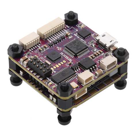
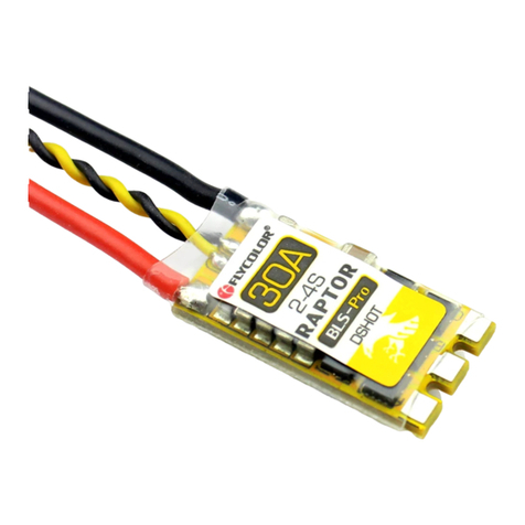
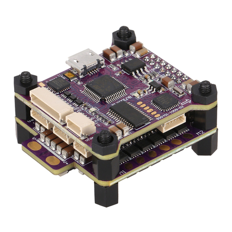
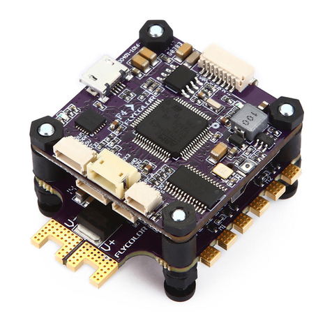
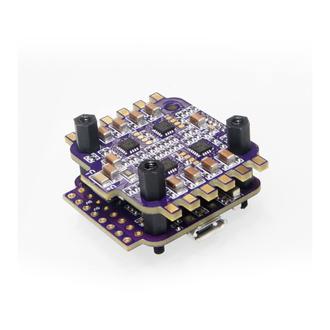
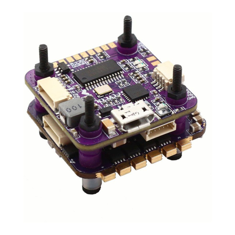
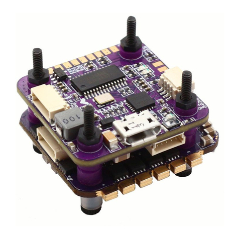
*All pict ures are for referen ce only
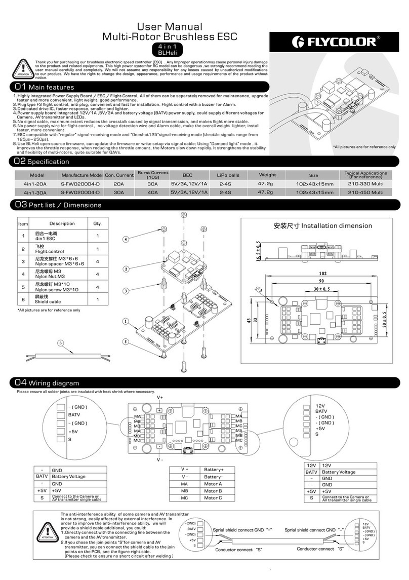
*Please ensure all solder joints are insulated with heat shrink where necessary.
1. Rampup power:
Rampup p ower can be set to relat ive values from 3% to 15 0%. This is the maxim um power that is allow ed when ramping up at lo w rpms an d during star tup. Fo r
low rpms , the maximum power to t he motor is limited, i n order to facilitat e detec tion of low B E MF voltages.
Rampup p ower also affects bid irect ional opera tion, a s the paramet er is use d to limit the power app lied during direct ion reversal.
During s tartup, the actual a pplie d power depen ds on thr ottle input , and can b e lower than the maxim um level set by the ramp up power parameter, b ut the
minimu m level is a quarter of th e maximum level.
2. Motor timing:
Motor ti ming can be set betwee n approximately 1° a nd appr oximately 3 1° in app roximatel y 1° incr ements (actual acc urate values here ar e 15/16ths of a degree ).
Typica lly a medium se tting w ill work fine, but if the m otor stutte rs it can b e beneficial to incre ase timing. Some mot ors with high induct ance ca n have a very lon g
commut ation demagnetiz ation time. This ca n result in motor stop o r stutter upo n quick t hrottle increase , particularly whe n running at a low rpm. Se tting timing
to high wi ll allow more time for d emagn etization , and oft en helps.
3. PW M frequency:
Motor pw m frequency can be pro grammed between 16 kHz and 4 8kHz. Highe r pwm fre quency can run motor s smoother. Program mable frequency al so allows for
moving o f small but potentia lly dis turbing hum ps in the t hrottle res ponse . All E SCs hav e these bumps , with BL H e li_32 t hey can be moved in the rp m range, to a
place wh ere the system has low s ensitivity to them .
4. Demag compensatio n:
Demag co mpensation is a feat ure to protect from mo tor stalls caused by l ong win ding demagn etiza tion time after comm utation. The typical symptom i s motor
stop or st utter upon quick thr ottle increase, pa rticularly when ru nning a t a low rpm. As ment ioned a bove, setting high c ommutation timin g normally helps, bu t
at the cos t of efficiency. Generally, a highe r value of the compens ation parameter gi ves better protect ion. If demag compen satio n is set too high , maxim um power
can be som ewhat reduced.
5. Maximum Acceleration:
Maximu m acceleration can b e set between 0.1%/m s and 25. 5%/ms. It can a lso be se t to maximum, i n which c ase acceler ation i s not limited . Limit ing acceleration
is prima rily intended as a bac kup par ameter that c an be use d in cases wher e too har d acceleration giv es desyncs. When set ting to e.g. 10%/ms, i t means that the
power ap plied to the motor is no t allowed to increas e by more t han 10% per mil lisec ond.
Programming parameters below can be accessed from the configuration software ( BL HeliSuite32):
1. Power up: 2.Throttle signal detected
(arming sequence start):
Once Once
3.Zero throttle detect ed
(arming sequence end):
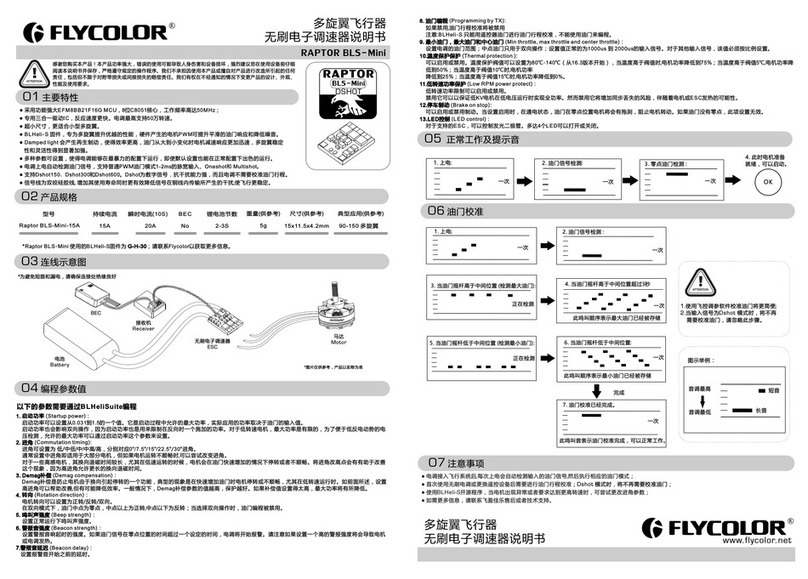
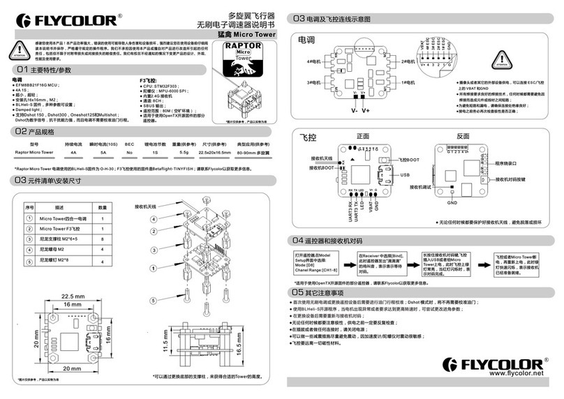
01 Main features
1.Power up: 2.Throttle signal detected
(arming sequence start):
Once
3.When throttle is abo ve midstick
(measuring max throttle): 4.If throttle is above midstick for 3 seconds:
This beep sequence indicates that max
throttle has been stor ed
Once
While
measuring
5.When throttle is below m idstick
(measuring min throttle):
While
measuring
6.If throttle is below midstick for 3 seconds:
This beep sequence indicates that min
throttle has been stor ed.
Once
Complete
7.Throttle calibrati on is complete.
After this, the motor wi ll run.
Once
Example:
Highest tone
Lowest tone
1.Throttle calibrati on will be more simple if
using Flight Control ler Configurator.
2.When the input signal is Dshot, throttle
calibration is disab led, and the throttle
calibration values a re ignored.
● ES C will automatically detect the input throttle signals every time as soon as it powered on, and then execute the corresponding signal-receiving
mode.
● User need to calibrate the throttle range when starting to use a new E SC or another transmitter. When the input signal is Dshot, throttle calibration
is disabled.
● When some abnormality occurs in E SC driving the motor or need the motor to reach a higher R PM, user can try to change the timing.
It is suggested that keep the ground wire in the original signal wire connecting well.●
● Please use a P DB or Flight Control with currentmeter if O SD is required to display the current.
● Please contact Flycolor sales or technical support for more information.
Ba t tery
Re c eiver
BE C
ES C
Mo t or
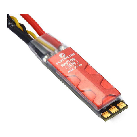
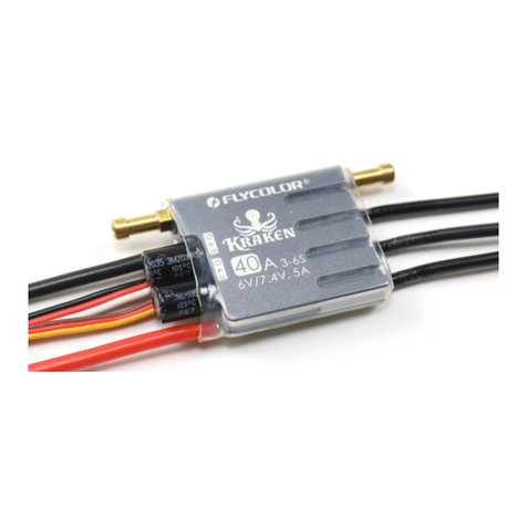
40A 3-6S 6.3g
No 29x14x6mm
Con. Current
ATTENTION
Model
OK
Once
4.After this, the
motor will run.
ATTENTION
X-Cro s s BL-32
Short beep
Long beep
X-Cross B L -32-35A 35A
*All pic tures are f or re fere nce o nly
6. Direction:
Rotati on direction can be se t to fwd/rev/bidir ectio nal fwd/bid irect ional rev. In b idirectional mod e, center throttle i s zero and above is fwd ro tatio n and below is
revers e rotation. When bid irectional opera tion is s elected, th rottl e calibrati on is dis abled.
7. Beep strength: Set s the strength of beep s under n ormal opera tion.
8. Beacon strength:
Sets the s trength of beeps whe n beeping beacon bee ps. The E SC will start be eping b eacon beeps if the thr ottle signal has bee n zero for a giventime . Note th at
settin g a high beacon streng th can ca use hot motor s or E SCs!
9. Beacon delay:
Beacon d elay sets the delay be fore be acon beepin g start s.
10.Throttle Cal Enable:
If disab led, throttle cali bration is disable d.
11. Min throttle, max throttle and center throttle:
These s ettings set t he thro ttle range of t he E SC. Cen ter throttle is only u sed for b idirectio nal ope ration. Th e values given for the se settings are for a no rmal
1000us t o 2000us input signa l, and fo r the other inp ut sign als, the valu es must b e scaled. For D shot in put signal, these se ttings have no effect .
12.Thermal protect ion:
Therm al protecti on can be e nabled or disabled . And the temperature t hreshold can be prog rammed The p rogra mmable threshold i s primarily meant as a s upport
for hard ware manufacture rs to use, as different h ardwa res can have di fferen t tolerances on the ma x temperatures of th e various componen ts used.
13.Low R PM power protect:
Power li miting for low RPMs can be enable d or disa bled. Disab ling it c an be necessary in ord er to achieve full pow er on some low kV motors r unnin g on a low
supply v oltage. However, di sabli ng it increas es the ri sk of sync loss , with th e possibility of toa sting motor or ESC.
14.Low Voltage Protection:
Low volt age protection can b e set between 2.5V and 4 .0V per l ipo cell. Or it c an be dis abled. When e nable d, it will limit power a pplied to the motor if t he battery
voltag e drops below the prog ramme d threshold . This feature is pri marily intended fo r fixed wing crafts.
15.Brake on stop:
Brake on s top can be set between 1 % and 100 %, or disable d. When n ot disabled , brake w ill be applied when th rottle is zero. For no nzero throttle, th is setting
has no effe ct.
16. L ED Control: LE D s can be control led on ES C s t hat support it.
17.Non Damped Mode:OFF- Damped light is available ; ON- No Dam ped light。
18.Music Note Config: Set up pers onali zed music.
BL 3 2-
cross
X
LED
RGB
170-450 Multi
55A 3-6S 10g
No 33x16x6mm
X-Cross B L -32-45A 45A Red Led
170-450 Multi60A 3-6S 10g
No 33x16x6mm
X-Cross B L -32-50A 50A Red Led
A·45A50
35A
*1)45A/50A firmware:Flycolor_X_Cross_ B L_32; *2)35A firmware:Flyc olor_X_Cross_BL _32_35A
02 Specifications
03 Wiring diagram
04 Programming parameter
05 Beeps-Normal operation
06 Beeps - Throttle calibration
07 Other Attention
www.flycolor.net 251400 -1081 -02, V2.2
